INTERFACE ALERT SYSTEM (IAS)
The Interface Alert System (IAS) has evolved from a rudimentary design in the trial Interface Master Module (IMM) to a system that is slighly more advanced that can aid in troubleshooting should a problem occur. The IAS is not a module, but a system of LED lights that have been configured to turn on and off in a combination of colours and time sequenced flashes.
The Interface Alert System is part of the Throttle Interface Module (TIM) and the Throttle Communication Module (TCM) and includes:
The Interface Alert System (IAS)
The Interface Alert Bar (IAB)
The Sector Alert Bar (SAB)
The Power Management Button system (PMBS also known as the 'traffic lights')
If a problem occurs with any of the interface cards, or wiring within a connected module, or there is a power issue, the LEDs will illuminate in a pre-defined colour combination to provide a visual warning as to which system is not functioning correctly.
The system of coloured LEDs is used to indicate:
Power connection
Wire continuity between cards and their OEM components
Connectivity between sub-systems
The IAS connects with the Throttle Interface Module (TIM).
The Throttle Communication Module (TCM) uses another very basic alert system. It wasn't deemed necessary to have a warning system included with the System Interface Module (SIM) as the design and function of this module is relatively simple.
IAS – Throttle Interface Module (TIM)
The Throttle Interface Module (TIM) incorporates two alert systems (Interface Alert Bar and Sector Alert Bar) and one Power Management Button System (PMBS).
The Interface Alert System (IAS) located on upper lid of TIM. Two strips of LED lights are used to indicate connectivity and aid in problem solving. The three 'traffic lights' are part of the Power Management Button System (PMBS) and are observed adjacent to the single USB cable
The Interface Alert Bar (first system) comprises a row of eight LED lights located on the upper lid of the module. The first LED is coloured red and illuminates when the module receives power.
The adjacent five LEDS are coloured green and indicate successful connection between the computer and interface cards (within TIM).
If a green light on the LED strip is extinguished then a problem exists with whatever card is associated with that LED. There is one green LED for each interface card. The remaining two LEDs are also coloured green, however, are not activated, but are included in the LED strip to cater towards possible expansion.
The Sector Alert Bar (secondary system), located adjacent to the first (IAB), incorporates three coloured LEDs in a three-light LED strip. This LED strip is used for troubleshooting. A combination of coloured LEDS serves as a visual cue to which sector, relay, or device is not working correctly.
For example, a solid green LED indicates that the the speedbrake logic for the rejected takeoff (RTO) is correct. A amber LED indicates that the speedbrake logic concerning speedbrake auto deploy and stow is correct.
If a problem exists that is not made apparent by the Interface Alert System (IAS), it is a relatively easy affair to install 'jumper wires' between interface cards, relays and terminal blocks to establish a customised LED light colour sequence to troubleshoot a particular problem.
Power Management Buttons (PMBS) - 'Traffic Lights'
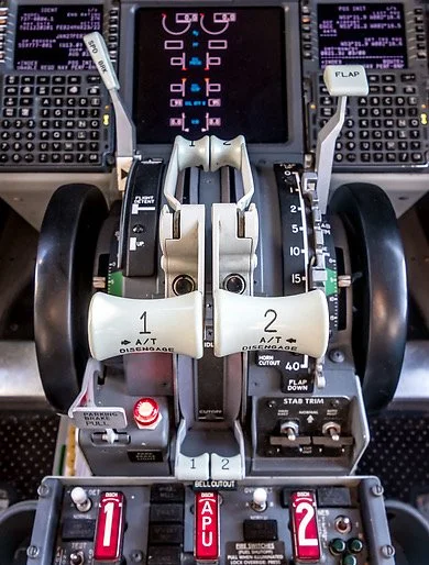
The banner photograph shows a portion of the Power Management Button System (PMBS). The PMBS, also known as the traffic lights is used to turn on and off the various sectors within the Throttle Interface Module (TIM).
Although the traffic lights are not really part of the Interafce Alery System; they will be discussed as they can be used as an aid in troubleshooting problems.
The traffic lights, consist of three push to engage buttons, that can turn on or off the various sectors as well as the autothrottle automation. Each button is a different coloured LED.
Depressing the red traffic light will turn on the 5-Volt sector which will power the Belkin hub and the various accessory gauges located on the TIM. The Green traffic light will engage the 12-Volt sector, and the blue traffic light engages only the throttle automation (autothrottle).
Rudimentary Alert System – Throttle Communication Module (TCM)
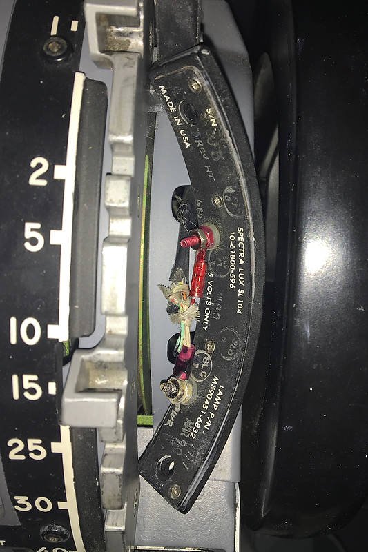
Rear of the TCM attached to the throttle quadrant showing the 3 LEDS and straight-through cables
The Throttle Communication Module (TCM) also has a rudimentary Interface Alert System. Three coloured LEDS located on the forward side of the TCM provide a reference to determine correct operation of the throttle.
A solid red coloured LED indicates that there is a complete connection between the throttle unit and the Throttle Interface Module (TIM). If the red light is not solid, this indicates that there is a connection/continuity problem located between he TCM and TIM. If the red light is solid – the flight can commence.
A solid green coloured LED indicates that the speedbrake logic is correct without a problem. Whenever the speedbrake lever is placed in the armed position or is in the UP position, the green LED will be solid. Failure of this light indicates that the speedbrake logic is not operating correctly.
The third purple coloured LED, which has the capacity to flash, indicates the status (on/off) of the 12-Volt actuator. The actuator, located on the captain-side of the throttle quadrant, controls the parking brake lever.
The actuator should only energise when forward pressure is applied to the toe brakes and the parking lever is raised. When the parking brake lever is set, the actuator will disengage and the purple LED will stop flashing. If the LED does not extinguish, it is a warning that the actuator has not disengaged and has mechanically become jammed in the energised position.
The three LEDS are not visible during flight and are designed for troubleshooting and testing purposes.
The Future
The Interface Alert System (IAS) will be expanded to encapsulate the interface module that will control the forward and aft overhead panels. The overhead panel is yet to be implemented in the simulator.
Using LEDs in conjunction with a multimeter, allows the major simulator systems to be interrogated relatively quickly, minimising the frustration and downtime that troubleshooting can cause.
Updated 03 February 2024