B737-800 NG Fuel Flow Reset Switch - OEM Switch Installed and Functional
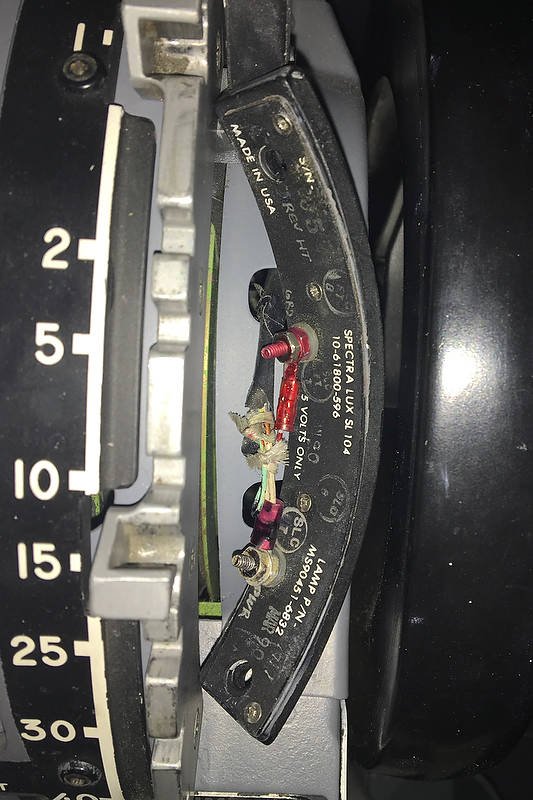
/oem 737-800 fuel flow switch can clearly be identified by its bulbous head. I have observed that on some air frames this switch has a cross hatch design
I have replaced the reproduction Fuel Flow Reset Switch (FFRS) with an OEM switch. I was not happy with the reproduction switch, which did not function correctly or look anything like the real switch used in the aircraft; the genuine switch is spring-loaded, quite large, and has a bulbous head. The FFRS is a new switch which was probably destined to be installed into a Boeing Next Generation aircraft.
FFRS Functionality
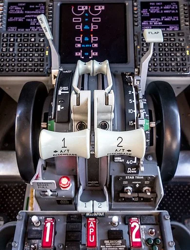
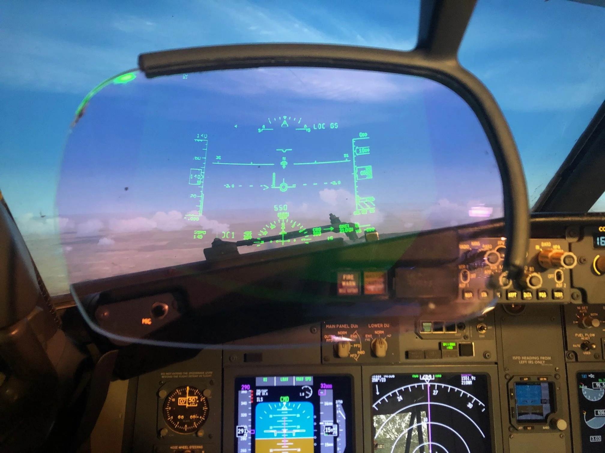
The Fuel Flow Reset Switch resides on the center forward panel immediately above the central display unit on the Main Instrument Panel (MIP). The function of the FFRS is to provide information on the fuel flow and fuel used. The fuel flow/used indications are displayed on the lower display unit (depending on your avionics set-up preferences).
The switch is a one-pole spring-loaded two-stage three-way momentary toggle switch. The normal 'resting' position of the switch is in the central (RATE) position. In this position the display unit indicates the fuel currently being used. Pushing the switch downwards to (USED) changes the display indication to read the fuel that has been used. Pulling the bulbous knob towards you whilst simultaneously pushing the switch upwards (RESET) resets the fuel used to zero. The downward and upward throw of the switch is momentary which means that when the switch is released it will automatically return to its central "resting" position.
The reason the switch is two stage for upwards deployment (pull and push upwards) is for safety; a flight crew cannot inadvertently push the switch to the upwards position resetting the fuel used.
Installation and Wiring
Depending upon what MIP you are using, installation of the switch may require enlarging the circular hole in the MIP. This is to enable the shaft of the OEM switch to fit through the MIP frame and the light plate of the Center Forward Panel. If the hole must be enlarged, care must be taken to not damage the light plate.
If the MIP you are using is 1:1 ratio, then the switch should fit through the hole perfectly. The switch is secured behind the light plate with a hexagonal nut. This switch fits the FDS MIP without need for enlarging the hole.
The rear of the FFRS has three standard-style screw post connections, each connection being either positive, negative or common (earth). To determine which throw of the switch does what, it’s necessary to use a multimeter set to continuity (beep mode). Place the black probe of the multimeter on the central screw post and then place the red probe on either of the other two screw posts. When you move the switch you will hear an audible beep indicating that function is “active” for that screw post.
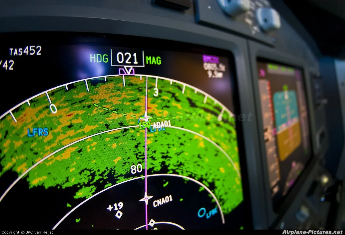
diagram 1; fuel flow switch display indications (copyright Boeing fcom)
Interfacing
An I/O card is required for the switch to interface with the avionics suite. A PoKeys card will suffice; however, I have used a Phidget 0/16/16 card; this card is installed in the SMART module. This card has been used primarily because it had unused inputs.
Establishing the correct functionality is done within the flight avionics software. If using ProSim737 it’s a matter of finding the fuel flow switch functions within the switches section of the configuration menu and assigning them. Failing this FSUIPC can be used.
The FFRS is but a small item; however, many small items make a sum. By using an OEM switch, you have the correct functionality of the switch in the simulator, and you improve the aesthetics.
The serial/part number for the switch is: MS-24659-27L, or for the non military specification 1TL1-7N.
Acronyms and Glossary
FFRS – Fuel Flow Reset Switch (also known as the Used Fuel Toggle)
OEM – Original Equipment Manufacturer
MIP – Main Instrument Panel
Momentary Switch - a switch which can be pushed downwards or upwards and when released returns to a central "resting" position
Two-Stage Switch - A switch that requires two events to activate the switch. For example, simultaneously pulling and pushing upwards on the switch