OEM 737-800 Lights Test Toggle Switch - Wired and Installed to MIP
/OEM Lights Test Switch (before cleaning...) One switch comprising several switches
The lights test is an often misunderstood but simple procedure. The light test is carried out by the crew before each flight to determine if all the annunciators are operating correctly (illuminating). The crew will toggle the switch upward to lights test followed by a routine scan of each annunciator on the overhead, center pedestal and instrument panel. An inoperative light may preclude take off.
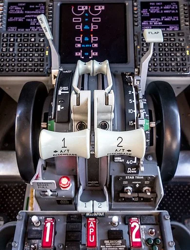
The lights test switch is a three-way switch which can be placed (and locked) in one of three positions; it is not a momentary switch. Toggling the switch upwards (lights test) illuminates all annunciators located in the MIP, forward and aft overhead and fire suppression panel (wheel well annunciator may not illuminate), while the central position (BRT) provides the brightest illumination for the annunciators (normal operation). Toggling the switch downwards activates the DIM function dimming the brightness by roughly half that observed when the toggle is in BRT mode.
Depending upon which manufacturer’s Main Instrument Panel (MIP) you are using, the toggle switch may not function this way. For example, Flight Deck Solutions (FDS) provide a three-way momentary toggle which is not the correct style of switch. You should not have to hold the toggle to light test as you make your pre-flight scan. The real toggle switch in the Boeing 737 aircraft is not a momentary switch.
Anatomy of the Toggle Switch
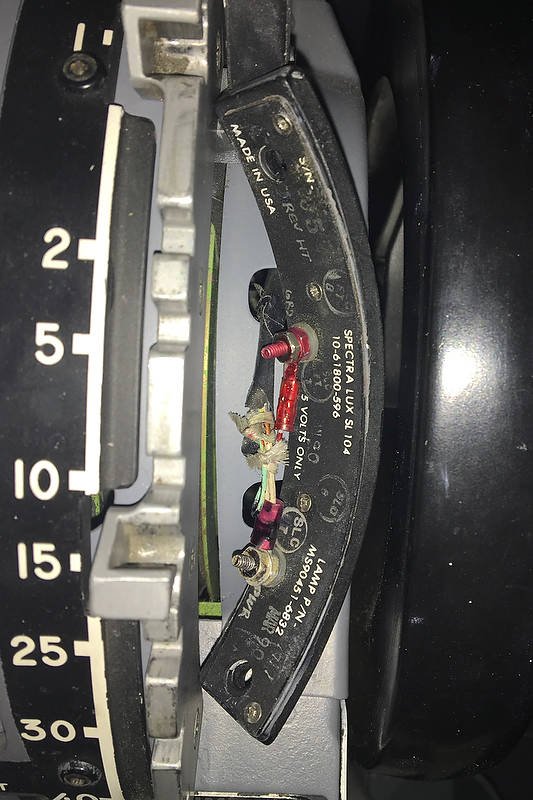
The OEM Light Test switch may appear to be a ‘glorified’ toggle switch with an aviation-sized price tag; however, there is a difference and a reason for this high price tag.
The switch although relatively simple in output, encompasses 18 (6+6+6) high amperage individual switches assigned to three terminals located on the rear of the switch. Each terminal can be used to connect to a particular aircraft system, and then to each other. This allows the toggle switch to turn on or off multiple aircraft systems during the light test.
The purpose of these multi-terminals is to allow the toggle switch to cater towards the high amperage flow of several dozen annunciators being turned on at any one time during the lights test, in addition to generators and other aircraft systems that are not simulated in Flight Simulator. In this way, the switch can share the amperage load that the annunciators draw when activated during the light test.
The switch can control the annunciators (korrys) for the MIP, forward overhead, aft overhead, fire suppression panel and any number of modules located in the center pedestal.
OEM Lights Test switch. The appearance of the OEM switch is not dissimilar to a normal toggle switch; however, the functionality is different in that there are a number of terminals on the rear of the switch to allow multi-system connection
Terminals, Interfacing and Connection
To determine the correct terminals to be used for the light test is no different to a normal toggle-style switch.
First, ascertain which of the six terminals correlate to the switch movement (toggle up, center and down). The three unused terminals are used to connect with other systems in the real aircraft (not used in Flight Simulator).
To determine the correct terminals for wiring, a multimeter is set to conductivity (beep) mode. Place one of the two multimeter prongs on a terminal and then place the other prong on the earth (common) terminal. Gently move the toggle. If you have the correct terminal for the position of the toggle, the multimeter will beep indicating an open circuit. The toggle switch does not require a power source, but power is required to illuminate the annunciators during the lights test.
For an overview of how to use a multimeter see this post - Flight Deck Builders Toolbox - Multimeter.
Daisy Chaining and Systems
Any annunciator can be connected to the light test function, and considering the number of annunciators that the light test function interrogates, it is apparent that you will soon have several dozen wires that need to be accommodated.
Rather than think of individual annunciators, it is easier to relate a group of like-minded components as a system. As such, depending upon your simulator set-up, you may have the MIP annunciators as one system, the overhead annunciators as another and the fire suppression panel and modules mounted in the center pedestal as yet another. If these components are daisy chained together (1+1+11+1+1=connection), only one power wire will be required to be connected at the end of the array. This minimises the amount of wire required and makes connection easier with the toggle switch.
Two Methods to Connect to the Switch
There are two ways to wire the switch; either through the flight avionics software (software-based solution), or as a stand-alone mechanical system. There is no particular benefit to either system. The software solution triggers the Lights Test by opening the circuit on the I/O cards that are attached to the computer, while, the mechanical system replicates how it is done in the real Boring aircraft.
Switch in-line (software connection using ProSim737)
The on/off terminal of the toggle switch is connected to a Leo Bodnar card or other suitable card (I use a Flight Deck Solutions System card), and the card’s USB cable connected to the main computer. Once the card is connected, the avionics suite software (ProSim737) will automatically register the card with to allow configuration. Depending upon the type of card used, registration of the inputs and outputs for the card may first need to be registered in Windows (if using Windows 7 type into the search bar joystick and select calibration).
To configure the toggle switch in ProSim737, open the configuration/switches tab and scroll downward until you find the lights test function. Open the tab beside the name; select the appropriate interface card (Leo Bodnar card) from the drop down menu and save the configuration.
ProSim737 will automatically scan the interface cards that are installed, and if there is a card that has a power requirement, such as a Phidget 0/16/16 card (used to convert OEM annunciators, modules and panels), the software will make a connection enabling the lights test to function.
Considering the connection is accomplished within the ProSim737 software, it stands to reason the lights test will only operate when ProSim737 is open.
To illuminate the annunciators when the switch is thrown, a 28 volt power supply will need to be connected to the annunciators either separately or in a daisy chain array.
OEM aviation relay mounted in center pedestal
Stand-alone (mechanical connection)
The second method, which is the way it is done in the real aircraft, is to use an OEM 50 amp 6 pull/6 throw relay device.
Depending upon the type of relay device used (there are several types), it may be possible to connect up to three systems to the one relay.
Lights Test Busbar
Although the Lights Test switch has the capacity to connect several systems to the switch itself, it would be unmanageable to attempt to connect each panel to the lights test switch.
To solve this issue a centrally-placed aviation-grade relay has been used in association with a busbar.
A benefit of using an OEM relay and busbar is that the relay acts as a central point for all wires to attach. The wires from the various systems (panels, korrys, etc) attach to the busbar which in turn connects to the various posts on the relay.
The relay will then open or close the relay enabling power to reach the annunciators (via the busbar) when the switch is positioned to Lights Test.
The stand-alone system will enable the lights test to be carried out without ProSim737 being open.
Although the relay is not large (size of a small entree plate), it can be problematic finding a suitable area in which to mount the relay where it is out of the way. A good location is to mount the relay inside the pedestal bay either directly to the platform floor or to a wooden flat board that is screwed to the lower section of the center pedestal.
Using the DIM Functionality (toggle thrown downwards)
This post has only discussed the lights test. The DIM switch is used to dim the OEM annunciators (korrys) for night work.
Another article explains the DIM functionality.
Diagram 1: basic overview to how the oem lights test toggle is connected
diagram 2: flow schematic between oem light test toggle and annunciators