Repair Backlighting on Throttle Quadrant
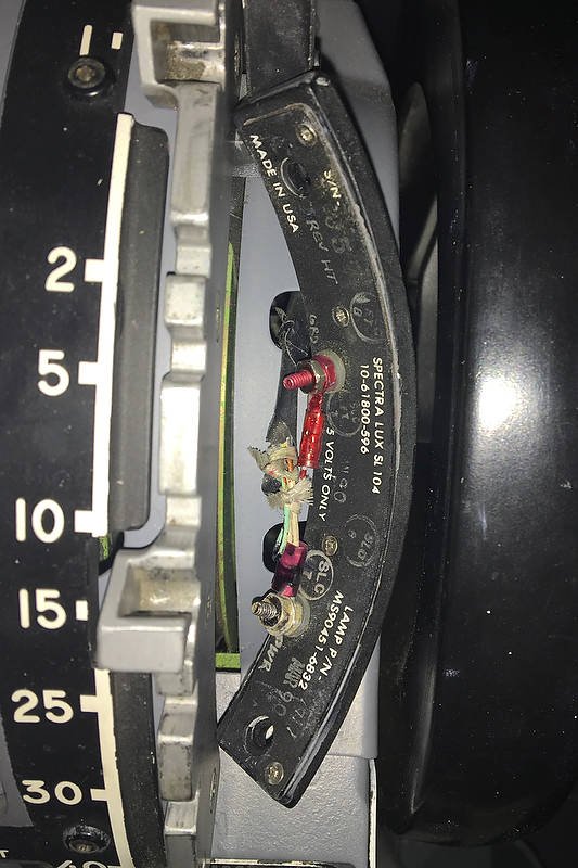
/The rear of the First Officer side trim lightplate showing one of the two terminals that the wiring loom connects to
During a recent flight, I noticed that the bulbs that illuminate the backlighting for the trim and flaps lightplate (First Officer side) had failed, however, the backlighting on the Captain-side trim lightplate was illuminated. My first thought was that the 5 volt bulbs that are integrated into the lightplate had burned out; after all, everything has an end life.
Backlighting - Wiring Loom
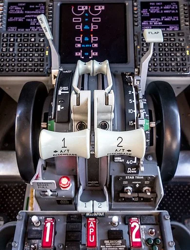
The wiring loom that supplies the power for the backlighting enters the throttle quadrant via the front firewall, and initially connects with the trim lightplate and parking brake release light on the Captain-side. A Y-junction bifurcates the wire loom from the Captain-side to the First Officer side of the quadrant, before it snakes its way along the inside edge of the quadrant firewall to connect with the First Officer side trim lightplate, and then the flaps lightplate. The wiring loom is attached securely to the inside edge of the throttle casing by screwed cable clamps.
The backlighting for all lightplates is powered by 5 volts and the backlighting on the throttle quadrant is turned on/off/dimmed by the pedestal lighting dimmer knob located on the center pedestal.
Finding the Problem
Ascertaining whether the bulbs are burned out is uncomplicated, however, assessing the terminals on the rear of each lightplate, and the wiring loom the connects to the lightplates, does involve dismantling part of the throttle quadrant.
The upper section of the throttle quadrant must be dismantled (trim wheels, upper and side panels, and the saw tooth flaps arc). This enables the inside of throttle quadrant to be inspected more easily with the aid of a torch (lamp/flashlight). When removing the trim wheels, be especially vigilant not to accidently pull the spline shaft from its mount, as doing so will cause several cogs to fall out of position causing the trim mechanism to be inoperable.
After the lightplates have been removed, but still connected to the wiring loom, a multimeter is used to read the voltage of each respective terminal on the lightplate. If the mutlimeter indicates there is power to the terminals, then the bulbs should illuminate.
What surprised me when this was done, was that the bulbs worked perfectly. Therefore, it was clear the problem was not bulb, but wire related.
Process of Elimination
The process of elimination is the easiest method to solve problems that may develop in complicated systems. By reducing the components to their simplest form, a solution can readily be attained.
Alligator wire connects power from Captain-side lightplate to the First Officer lightplate. Note the frayed outer layer of the white aircraft wire. The gold colour is a thin layer of gold that acts as a fire retardant should the wiring overheat
If you suspect that the wiring is the problem, and don't have a multi meter, then a quick and fool safe method is to connect an alligator cable from the positive terminal of the Captain-side lightplate to the respective terminal on the First Officer lightplate. Doing this removes that portion of the wiring harness from the circuit.
In this scenario, the bulbs illuminated on both trim lightplates. As such, the problem was not bulb related, but was associated with the wiring loom.
It must be remembered that the wire used to connect the backlighting in the throttle quadrant is OEM wire. As such, the age of the wire is the same age as the throttle quadrant.
Inspecting the wire loom, I noticed that one of the wires that connected to the terminal of the lightplate was severed (cut in two). I also noted that the original aircraft wires had begun to shed their protective insulation layer.
Aircraft Wire and Insulation Layers
The high voltage and amperages that travel through aircraft wire can generate considerable heat. This is why aircraft wire is made to very exacting standards and incorporates several layers of insulation that surround the stranded stainless steel wire. The use of high-grade stainless steel also provides good strength and resistance to corrosion and oxidation at elevated temperatures.
The green wire has been severed. A possible scenario was that the wiring loom had been pulled slightly loose from the throttle chassis, and had become caught in the flaps mechanism. When the flaps lever is moved, the mechanism can easily crimp (and eventually sever) any wire in its path. If you observe the white wire you can see the insulation that is shedding
Interestingly, one of the insulating layers is comprised of gold (Au). The gold acts as an effective fire retardant should the wires overheat.
The breakdown of the upper insulating layer is not a major cause for concern, as a 'shedding' wire still has enough insulation to not arc or short circuit. However, the wire should be replaced if more than one layer is compromised, or the stainless threads of the wire are visible.
Possible Scenario
When inspecting the wiring loom, I noted that one of the screws that holds the cable clamp to the inside of the throttle casing was loose. This resulted in part of the wire loom to 'hang' near the flaps arc mechanism. It is possible that during the throttle’s operational use, the movement and vibration of the aircraft had caused the screw to become loose resulting in the wires hanging down further than normal. It appears that the wire had been severed, because it became caught in the mechanism of the flaps lever.
Unlike reproduction throttles, the parts used in an OEM throttle are heavy duty and very solid; they are designed to withstand considerable abuse. The speedbrake lever, when activated can easily cut a pencil in two, and the repeated movement of the flaps lever, when moved quickly between the teeth of the flaps arc, can easily crimp or flatten a wire.
Rather than try to solder the wires together (soldering stainless wire is difficult) and possibly have the same issue re-occur, I routed the wires from both lightplates (trim and flaps) directly to the 5 volt bus bar located in the center pedestal.
I could have removed the wire loom completely and replaced it with another loom, however, this would involve having to disassemble the complete upper structure of the throttle quadrant to access the wire loom attachment points on the inside of the throttle casing; something I was not keen to do.
Final Call
OEM parts, although used in a static and simulated environment can have drawbacks. Apart from age, the repeated movement of mechanical parts and the vibration of the spinning trim wheels, can loosen screws and nuts that otherwise should be securely tightened.
Acronyms
OEM – Original Equipment Manufacturer
Wire Loom – Several wires bundled together and attached to a fixed point by some type of clamp