Changing-out Joystick Cards - Leo Bodnar BU0836X Joystick Card
/Leo Bodnar BU0836X joystick card and enclosure
Most flight simulators require regular maintenance to ensure that all systems function correctly. During a routine overhaul, which included replacing the potentiometers that are used to calibrate the flight controls, it was discovered that a Leo Bodnar joystick card had been damaged. Rather than replace the card with the same type (BU0836A), I decided to change-out to a Leo Bodnar BU0836X joystick interface card and protect it with a dedicated metal enclosure.
I will not duplicate the detailed information that has already been written about the BU0836X on the Leo Bodnar website. Rather, I will examine the advantages of using this particular card.
The card and its protective enclosure can be purchased separately from Leo Bodnar Electronics in the United Kingdom.
BU0836A and BU0836X Joystick Card
The BU0836X 12-bit joystick interface card has been available for some time and is very similar to the BU0836A joystick card; the latter being the mainstay for interfacing various hardware. Both cards enable calibration of the joystick axes used for controls such as the ailerons, elevator, rudder, and the steering tiller, as well as interfacing with a various simulator buttons and knobs.
Key Advantages
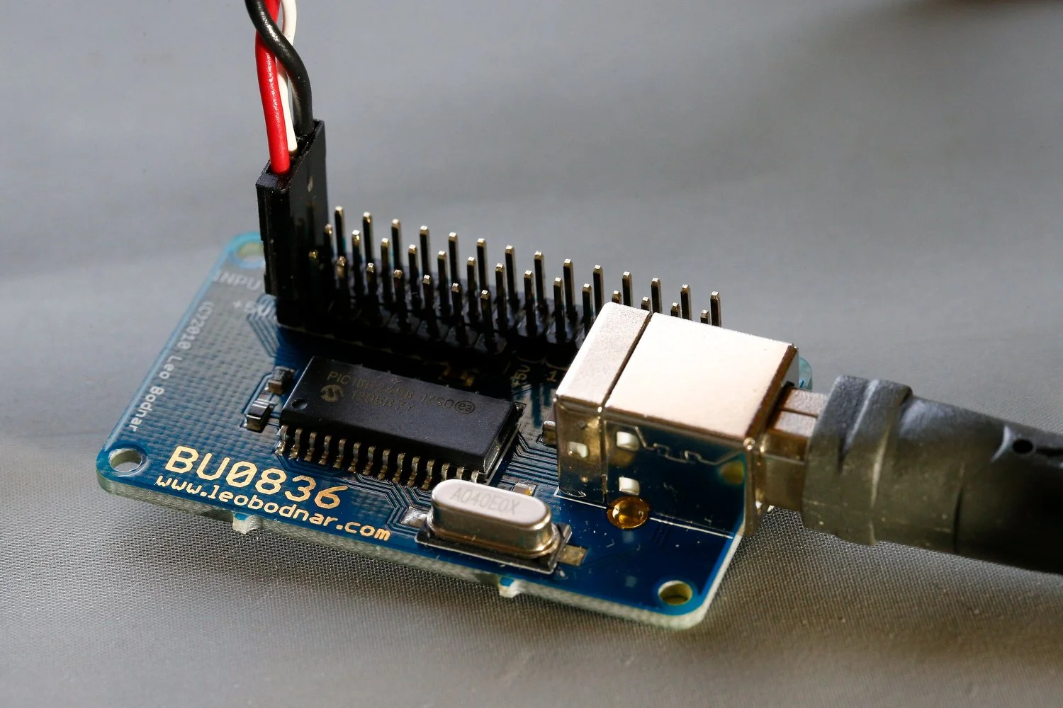
The primary advantage of the larger BU0836X card, aside from its additional inputs and outputs, is that it does not use the JR connectors found on the BU0836A card. JR connectors can be fiddly, prone to breaking (if not connected properly), and may become loose unless soldered directly to the card’s pins.
Over the years, I and cannot recall how many times a JR connector had worked its way loose from the vibration generated by the trim wheels rotating, and depending on the location of the card, a repair can be time consuming.
In contrast to using JR connectors, the BU0836X features push-to-secure connectors. This design allows wires between the gauge of 24-20 AWG (stripped to 9mm) to be easily inserted into the correct terminals and locked in place without requiring screws, solder, or JR connectors. It’s only a matter of pushing the tab on the card inwards and inserting the wire into the hole.
The push-to-secure design not only simplifies connection but also makes it easier to replace components like potentiometers or other hardware devices when necessary. Additionally, the terminal bar is colour-coded with clearly printed labels, making identification straightforward, thereby reducing the risk of wiring errors.
The card has 8 analogue inputs (potentiometers, knobs), 32 inputs (button, switches) and 1 joystick HAT controller.
I find that working with a slightly larger card is much easier than its smaller sister, although an obvious downfall is the space required to mount the BU0836X card. I also like the fact that the card is made in the United Kingdom; therefore, production inconsistencies that occur with many less expensive Chinese cards is not as prevalent.
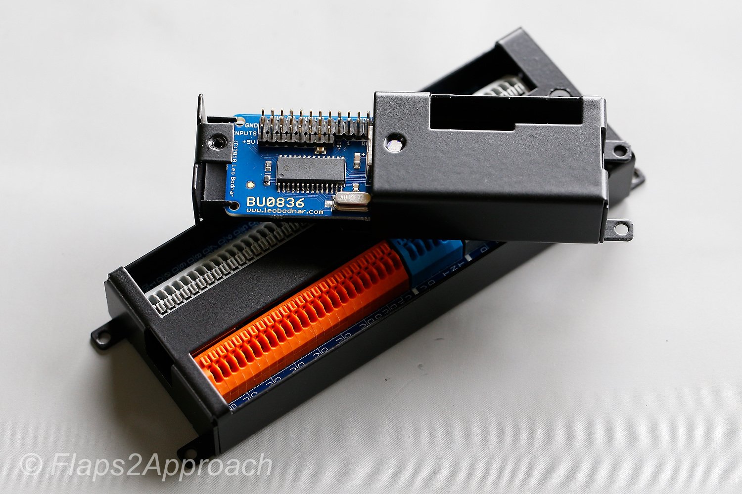
BU0836X Protection
The card can be mounted on a base plate using standoffs and screws. However, as with any hardware component, it is susceptible to damage from movement, accidental knocks, or falling objects - especially during maintenance (screwdrivers, pliers, eye glasses, coffee cups, mobile phones, i-pads, etc).
To address this, Leo Bodnar offers a protective enclosure that has been specifically designed for the BU0836X and BU0836A cards respectively. The enclosure comprises two pieces of metal with the inner piece (called the slider) designed to slide into and out of the outer casing. The card clips firmly into the inner slider and a small hex screw fastens the slider into the outer casing. Realistically, the hex screw is overkill as the inner slider fits quite firmly, and I very much doubt that the slider will accidentally slide out of the outer casing. The enclosure can then be attached to a base plate using four screws.
Once secured inside the enclosure, the card remains firmly in place and does not move or wiggle, ensuring excellent stability. This setup provides robust protection against physical damage while keeping the terminals fully accessible.
The enclosure has been well designed, is fabricated from metal, powder coated, and coloured black.
Additional Considerations
Despite the protective enclosure, the wiring remains exposed to the environment, leaving it vulnerable to dust and dirt accumulation. If this is a concern, a simple and effective solution is to fabricate a small plastic cover to shield the card and its wiring. A repurposed plastic takeaway container works well for this purpose, providing an inexpensive and practical way to keep the card clean and secure.
Calibration
The BU0836X card is calibrated in the same way as the BU0836A card: initial registration in windows using the Game Controller (type JOY in the computer’s search bar) and then calibration in either flight simulator, ProSim737 or FSUIPC.
Final Call
The BU0836X card stands out for its well-thought-out design. Its larger size makes terminal identification and access easier, while the push-to-secure connectors provide reliable, solder-free connections. Although its size could be a disadvantage in tighter spaces, it works well for most applications where space constraints are not a concern. Additionally, the optional metal enclosure offers protection against physical damage, enhancing the card’s long-term durability.
For further information detailing how to use the BU086X joystick card.
This article is not endorsed by Leo Bodnar Electronics. Furthermore, I paid full price for the products discussed.
Below: Gallery showing photographs of the BU0836X and BU0836A joystick cards and enclosures.