
Disconnecting the Autothrottle and Autopilot (Normal and Non-Normal Operations)
/
Mode Control Panel (MCP) showing A/T toggle and speed window
This article will examine the use of the autothrottle during normal operations and explore several non-normal conditions, highlighting both the advantages and potential drawbacks. It will also discuss the relationship between the autopilot and autothrottle, offering insight into why the recommended procedure is to operate them in unison, rather than using one without the other.
Note that single engine operation will not be addressed as this is a separate subject.
A search on aviation forums will uncover a plethora of comments concerning the use of the autothrottle which, combined with the use of the autopilot and non-normal procedures, can easily be misconstrued. An interesting discussion can be read on PPRuNe forum.
What is the Autothrottle
The Autothrottle (A/T) is a part of the Automatic Flight System (AFS) comprising the Autopilot Flight Director System (AFDS) and the flight management computer. The autothrottle provides automatic thrust control through all phases of flight and its functionality is designed to operate in unison with the Autopilot (A/P).
Autothrottle Use
The autothrottle is armed whenever the A/T toggle is set to the UP and latched position and the green-coloured annunciator is illuminated on the Mode Control Panel (MCP). The autothrottle is engaged when either the N1 or SPEED button annunciator is illuminated.
The autothrottle is usually engaged during the takeoff roll by pressing one or both TOGA buttons located under the thrust handles. TOGA, sometimes referenced as TO/GA (note diagonal line) is an abbreviation for Takeoff/Go-Around.
Stabilisation Criteria (during takeoff roll)
Allowing the engines to stabilise during the takeoff roll is important, as stabilisation prevents thrust asymmetry whereby one engine may spool at a slower rate during the commencement of takeoff thrust.
%N1 and %N2
TOGA is selected when %N1 readings stabilise for both engines (both arcs matched) at around 40%N1, and when the EGT numbers decrease slightly, typically after 2-3 seconds. Although %N1 (fan speed) is the primary reference for takeoff thrust monitoring, %N2 (core speed) which stabilises earlier at around 20-25% can also be monitored - but bear in mind %N2 is not the key metric.
The reason the autothrottle is used during takeoff, is to simplify thrust procedures during a busy segment of the flight and to ensure that both engines are generating similar thrust.
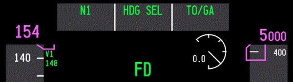
FMA Captain-side PFD showing n1 and TOGA annunciation during takeoff roll. A green coloured display indicates that a particular mode is active - green for go or green is live
Once engaged, the TOGA command mode will control the thrust outputs to the engines until the mode is exited, either at the designated altitude set on the MCP, or by activating another automaton mode such as Level Change (LVL CHG).
When TOGA is engaged, the Flight Mode Annunciator (FMA) will display N1 and TOGA. The FMA display indicates to the flight crew what the AFS is doing.
Important Point:
Always monitor the FMA to know what mode is selected and whether the mode is armed or engaged. The monitoring of the FMA cannot be understated.
The Autothrottle is Designed to be Coupled with the Autopilot
The autothrottle is a sophisticated automated system that will continually update thrust based on minor pitch and attitude changes and operates exceptionally well when coupled with the autopilot. But when the autopilot is not selected and the autothrottle is selected by itself, its reliability can be questionable.
Some individuals believe that during a landing with the autopilot off and the autothrottle engaged, a drop in airspeed, such as during the flare, will cause the autothrottle to apply thrust. While this is technically true, there is a lag between the initiation of the thrust command and the engines spooling to the commanded %N1. As a result, there is a risk of a tail strike as the aircraft’s pitch increases before the engines have produced the required thrust. Likewise, excessive wind gusts during the approach can lead to pitch coupling (discussed below).
The advantages of using the autothrottle and autopilot together (coupled) are:
Speed is stabilised;
Speed floor protection is maintained;
Task loading is reduced; and,
Flight crews can concentrate on visual manoeuvring and not have to be overly concerned with wind additives.
The disadvantages of using the autothrottle with the autopilot not selected are:
Additional crew workload and possible loss of situational awareness (due to workload);
Potential excessive and unexpected throttle movement caused by pitch and attitude changes;
Potential excessive airspeed when landing in windy conditions with gusts;
The potential for pitch coupling to occur (discussed below); and,
A loss of thrust awareness (out of the loop).
Important Point:
The autopilot and autothrottle should not be used independently of each another.
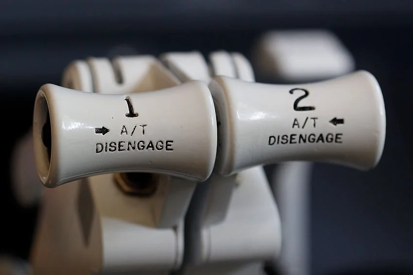
737 Next Generation thrust levers. TOGA and A/T disconnect buttons are just visible
Pitch Coupling
Pitch coupling occurs when the autothrottle system actively attempts to maintain thrust based on the aircraft’s pitch or attitude. It can occur when the autopilot is disconnected while the autothrottle remains engaged. In this situation, the pilot uses manual pitch and roll inputs to control the aircraft, while the autothrottle controls the thrust output.
The design of the 737 airframe is prone to pitch coupling because of its under wing mounted engines. The position of the engines cause the thrust vector to pitch upwards with increasing thrust and pitch down with a reduction in thrust.
When the autopilot is disconnected and the autothrottle is engaged, the pilot controls pitch manually while the autothrottle adjusts thrust to maintain airspeed. Because thrust changes influence pitch and pitch changes affect airspeed, the two systems can interact with each other. This coupling of pitch and thrust can create a roller‑coaster effect as the aircraft alternately increases and decreases pitch in response to pilot inputs and autothrottle driven thrust changes.
This coupling of pitch to thrust can be potentially hazardous; namely:
When flying an approach due to the lower above ground altitude and airspeed (closer to Vref); and,
In windy conditions whereby; the autothrottle will command the engine to spool up and down based on wind speed and gusts.
The autopilot and autothrottle have been designed to operate in unison, and the autopilot’s high level of fidelity can compensate for any variations in pitch and thrust output, as well as the inherent lag between commanded N1 settings and engine spool‑up.
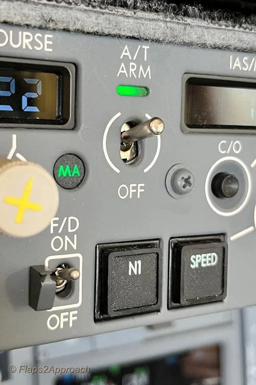
A/T ARM toggle, N1 and speed button. The N1 and speed button illuminate when either is in active mode. In the image, the A/T is armed; however, the speed option is not selected (the annunciator is extinguished). This enables thrust to be controlled manually
Autothrottle Non-Normal Operations (Arm Mode)
The primary function of the A/T ARM mode is to provide minimum speed protection.
The autothrottle system comprises two discrete functions - the A/T ARM toggle and the SPEED button, which operate either in combination or independently of each other. Both functions are accessed from the MCP.
During normal operations, the A/T ARM toggle is positioned in the UP position and the function of the SPEED button is coupled to the toggle. When selected, both functions display green-coloured lights on the MCP and the speed window displays the target speed.
During non-normal operations, the A/T ARM toggle and the SPEED button do not operate as a coupled system. To decouple the two functions, the SPEED button is pressed to disconnect the speed function. When disconnected, the green-coloured light will be extinguished and the speed window will be blank with no target speed displayed. This will place the autothrottle in the ARM mode.
When using the autothrottle in ARM mode, it is important to monitor the FMA to determine whether the autothrottle is armed or engaged. It is not prudent to rely solely on the green lights on the MCP, as these indications confirm only that a mode has been selected, not that it is actively engaged or performing as expected.
When in ARM mode, the FMA displays the word ARM in white letters within an outlined white box. Conversely, when the SPEED button is pressed (to engage speed mode), the colour of ARM changes from white (armed) to green (engaged).
Note that the outlined box on the FMA is initially displayed in white (armed/pre‑selected) to indicate that a mode change has been commanded. The box then changes to green (engaged) after approximately 10 seconds to signify the active mode.
Why Use ARM Mode
The primary purpose of decoupling speed from the autothrottle is to permit manual thrust control while retaining the autothrottle in the armed state. This can be advantageous during non-precision approaches. Recall that the autopilot and autothrottle must not remain engaged during the final stages of the approach and landing, except during an autoland.
The arming of the autothrottle is an expedient way to engage the autothrottle if a Go-Around is required - all that is required is to push the TOGA buttons on the thrust lever and the autothrottle will engage (rather than having to manually engage the autothrottle). This enables a Go-Around to be executed more expediently and with less workload.
If the approach proceeds smoothly and a go‑around is not required, the crew will, prior to landing, disengage the A/T toggle on the MCP by either manually moving the toggle to the OFF position or pressing the A/T buttons on the thrust levers. If the A/T toggle is not placed in the OFF position, the autothrottle system will automatically disconnect when the main wheels touch down, based on WOW logic (Weight‑on‑Wheels logic is triggered by the squat switches on the main landing gear, which activate when the shock strut is compressed by a predefined amount).
Although this procedure is favoured by some flight crews, this practice is not authorised by all airlines, with some company policies expressly forbidding the ARM A/T technique.
The reason this procedure is prohibited by some airlines is the variety of approach types the 737 can fly. Crews accustomed to precision approaches, where this technique is unnecessary, may become uncertain about the autothrottle’s behaviour, and there have been several incidents in which crews failed to notice significant airspeed changes.
The recommendation by Boeing in the 737 Flight Crew Training Manual (FCTM) states:
‘The A/T ARM mode is not normally recommended because its function can be confusing. The primary feature the A/T ARM mode provides is minimum speed protection in the event the airplane slows to minimum manoeuvring speed. Other features normally associated with the A/T, such as gust protection, are not provided’. (When the A/T is armed and the SPEED button not selected).
Important Points:
It is important that, if the autothrottle is disconnected or in ARM mode, the crew maintains vigilant monitoring of the aircraft’s airspeed.
The ARM mode is not suitable for all approach types and usually is only used for non-precision approaches.
Speed Protection (Windy, Gusty and Turbulent Conditions)
The autothrottle system provides speed protection through airspeed and acceleration sensing; however, its effectiveness depends on correct use of wind additives and an understanding of how the system behaves in gusty or turbulent environments.
To ensure adequate wind and gust protection when using the autothrottle during an approach in windy conditions, the command speed should be set to the appropriate wind additive. This additive is derived from the prevailing wind speed, direction, and gusts, and typically ranges between Vref +5 and Vref +20. Applying a wind additive provides a safety buffer that accounts for fluctuations in wind velocity and reduces the likelihood of the autothrottle commanding a speed that drops below Vref.
In turbulent conditions, the autothrottle maintains a thrust level that averages higher than the minimum required in order to preserve the commanded approach speed.
When to Apply Additives to Vref
Although the concept is comparatively straightforward, there is often uncertainty about the appropriate speed additives to apply to Vref, particularly regarding whether the autothrottle is in use. To clarify the process:
If the autothrottle is to be engaged for landing (for example autoland), set the command speed to Vref+5. There is no need to add wind additives as the autothrottle logic already compensates for gusts through airspeed and acceleration sensing.
If the autothrottle will be disconnected (or not selected) for landing, set the command speed to Vref plus the appropriate wind additive to account for steady wind and gusts. This will ensure that speed protection is provided.
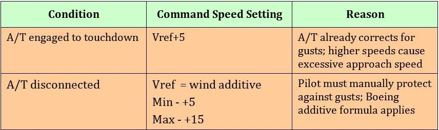
Table 1: Summary of A/T conditions, speed settings and reasons
Important Point:
Minimum speed protection is lost when the autothrottle is not engaged, or the SPEED function on the MCP is deselected.
Additional Information
For information on how to use the Wind Correction function in the CDU, refer to: Wind Correction Function (WIND CORR).
For information on how to calculate wind additives, refer to: Crosswind Landings Part 2.

A/T disengage button on throttle thrust lever (Captain-side). This is an OEM throttle from a 737-300 series (classic). The button is identical to that used in the NG with the exception that the thrust handles are usually white and not grey in colour. Depressing this button will disconnect the autothrottle
Manual Override - Engaging the Clutch Assembly
Occasionally, for any number of reasons, the flight crew may need to override the autothrottle.
The Boeing autothrottle system incorporates a clutch mechanism that allows the flight crew to manually advance or retard the thrust levers while the autothrottle remains engaged. When the thrust levers are moved, the clutch automatically disengages the servo drive, placing the autothrottle in an overridden state for the duration of the manual input.
This clutch arrangement provides the capability for immediate manual thrust intervention, whether for abnormal situations, rapid thrust changes, or any circumstance requiring direct pilot control.
Correct Sequence for Disconnecting the Autopilot and Autothrottle
There is considerable confusion as to when to disconnect the autothrottle and autopilot and in what order.
Whenever hand flying the aircraft, the autopilot and autothrottle must not be engaged. If they are engaged they both should be engaged, but which do you disengage first - autopilot or autothrottle. Best practice is to always disconnect the autothrottle before the autopilot. The reason being is that the aircraft ‘s autothrottle system has a slightly faster response time than the autopilot (the last thing you need is for the autothrottle to spool up after disconnecting the autopilot). Disconnecting both systems enables the pilot to have full manually control of the aircraft. Furthermore, do not disconnect both in rapid fire - take your time and wait a second between disconnecting the autothrottle followed by the autopilot. This enables a more seamless transition to occur.
To disconnect the autopilot and silence the autopilot disconnection horn:
Press the deselect button on the yoke - one click to disconnect the autopilot and a second click to silence the autopilot disconnection horn;
Press the CMD button on the MCP or;
Lower the disconnect bar on the MCP.
To disconnect the autothrottle:
Press the autothrottle disconnect buttons on the thrust levers; or
Move the A/T ARM switch on the MCP to the OFF position.
To extinguish the flashing autothrottle and autopilot annunciators on the AFDS either:
Press each of the AFDS annunciators that are flashing to extinguish the lights; or
Press the deselect button on the yoke and autothrottle disconnect buttons on the thrust levers.
Timing of Disconnect (four-click sequence)
Whilst disconnecting both the autopilot and autothrottle simultaneously is perfectly acceptable, it is generally preferable to do so in a controlled sequence. It is a four-click sequence.
One click of the throttle disconnect buttons disengages the autothrottle. A second click cancels the warning.
One click of the deselect button on the yoke disconnects the autopilot, a second click silences the aural alert.
Whether this makes a measurable difference is difficult to quantify, but a calm, deliberate disconnection sequence, with a slight pause between clicks, appears far more controlled and elegant than rapidly clicking multiple times in quick succession.
At What Altitude Should the Autothrottle be Disconnected
A common preference amongst flight crews, when flying a non-precision approach, is to disconnect the autopilot and autothrottle no later than 1500 feet AGL. This is the altitude at which the aircraft should be fully configured for landing, with landing checks completed, the landing gear down, flaps set to 30, and the aircraft established within the required vertical and lateral tolerances.
That said, the altitude is not fixed unless specified by airline policy. A useful maxim is to use the Decision Height (DH) or Minimum Descent Altitude (MDA) as the point at which to disconnect the autothrottle.
Disconnecting the autopilot and autothrottle earlier in the approach provides additional time to transition from automated to manual flight and to establish a feel for the aircraft before landing.
Many flight crews, particularly experienced pilots confident in manual flying, regularly choose to hand‑fly the aircraft. Some will fly from 10,000 feet to landing using the FD, ILS, VNAV, and LNAV cues on the PFD, supported by the ND for situational awareness. Hand‑flying the approach is widely enjoyed, even though it remains one of the most demanding phases of flight.
Important Point:
Whenever the aircraft is being hand‑flown with the autothrottle disconnected, it is essential to closely monitor airspeed. This is particularly critical on final approach, where thrust can decay quickly and bring the aircraft close to stall speed.
Hand Flying Without Automation
The benefit of flying with the autopilot and autothrottle disconnected is the ease with which the aircraft can be manoeuvred. The crew sets the appropriate %N1 to produce the thrust required to maintain the desired airspeed; gone are the thrust surges that occur as the autothrottle attempts to maintain speed. This technique is often referred to as ‘flying by the numbers’.
Granted, it takes considerable time and patience to become proficient at manual flying in a variety of conditions, but the overall enjoyment increases significantly.
Company Policies
Airline policies often dictate how a flight crew will operate an aircraft, and while some policies are expedient, they are more often based on economic considerations for the company.
Policies vary with respect to autothrottle use. For example, Ryanair, Air New Zealand, and Kenya Airways require the autopilot and autothrottle to be disconnected simultaneously. QANTAS follows a similar approach; however, they specify an altitude by which disconnection must occur (1500 feet AGL) and stipulate that the autothrottle is to be disconnected before the autopilot, with a distinct pause between each disconnection.
If an airline does not publish a policy, the decision is left to the discretion of the flight crew.
Simulator Nuances
The above information primarily discusses the systems as they operate in the real aircraft. Whether these systems are functional in a simulation depends on the avionics suite in use (Sim‑Avionics, Project Magenta, ProSim737, etc.).
For example, the autothrottle may not maintain the speed selected on the MCP under certain conditions, such as during turns in high winds. In the real aircraft, the crew would manually override the autothrottle. However, if the throttle hardware or avionics suite does not support manual override, the next best option is to either:
Disconnect the autothrottle and manually adjust thrust; or
Press the SPEED button on the MCP to place the autothrottle in ARM mode, allowing manual control of thrust. Once the manoeuvre is complete, the autothrottle can be re‑engaged by pressing the SPEED button again.
If your throttle does not support manual override, or the avionics suite does not model this functionality, the second option is an effective way to compensate for the limitation.
Final Call
There is little argument that the use of the autothrottle is a major benefit in reducing task loading; however, as with other automated systems, this benefit can come at a cost. This has led several airlines to introduce policies prohibiting the use of the autothrottle without the autopilot. Pitch coupling, excessive vertical speed, and incorrect thrust settings can all contribute to hard landings, possible nose‑wheel collapse, undesirable ground‑effect behaviour, or even controlled flight into terrain.
Ultimately, the decision to use the autopilot and autothrottle as a coupled system rests with the pilot in command and depends on crew experience, environmental conditions, and airline policy. However, Boeing’s recommendation is to avoid using the autothrottle without the autopilot engaged.
Additional Information:
737 Automatic Systems Review (Smart Cockpit).
Acronyms and Glossary
A/P – Autopilot.
A/T – Autothrottle.
AFDS – Autopilot Flight Director System .
Command Speed - the target airspeed that the autothrottle (A/T) is trying to maintain.
FCTM – Flight Crew Training Manual (Boeing Corporation).
FMA – Flight Mode Annunciator.
Manual Flight – Hand flying aircraft. A/P and A/T disconnected.
MCP – Mode Control Panel.
Minimal Speed Protection – Function of the A/T when engaged. The A/T has a reversion mode which will activate according to the condition causing the reversion (placard limit). (For example, flaps, gear, etc).
Pitch Coupling – The coupling of A/T thrust to the pitch of the aircraft. A/T thrust increases/decreases as aircraft pitch and attitude changes. Pitch coupling occurs when the A/P is disconnected, but the A/T is engaged.
Selected/Designated Speed – The speed that is set in the speed window of the MCP.
SPEED button – Located on the MCP the SPEED button (when not illuminated) disconnects the speed from the autothrottle system whilst keeping the autothrottle in the armed mode.
Take Off/Go Around (TOGA) – Takeoff Go-around command mode. This mode is selected during takeoff roll by depressing one of two TOGA buttons beneath the throttle levers.
Vref – Landing reference speed.


