Correct Technique For Extending or Retracting Flaps on the 737-800
/I have mentioned the flap extension schedule and procedures before, but because it is important it deserves its own article.
Flaps and airspeed are central to managing the 737‑800’s aerodynamic performance during takeoff, approach, and landing. Deploying flaps increases lift allowing the aircraft to fly safely at lower speeds and creates drag that slows the aircraft’s airspeed. Each flap setting has defined speed limits and associated target speeds that ensure the aircraft remains within structural and aerodynamic boundaries. Maintaining the correct airspeed for the selected flap configuration is important as it supports stable handling, predictable performance, and compliance with certified operating procedures.
In this article the following will be discussed:
Flap extension schedule;
The maximum flap extension speed;
The minimum manoeuvring speed;
The upper amber band;
The lower amber band;
The red and black band; and
When to extend or retract the flaps.
Flap Extension Schedule
All too often, novice virtual flyers do not adhere to the flap extension schedule. As a result, extending the flaps at the incorrect airspeed can cause high aircraft attitudes, unnecessary spooling of engines, excessive noise, and increased fuel consumption, which can lead to an unstable approach.
If the flaps are extended at the correct airspeed, the transition will be relatively smooth with minimal engine spooling.
The 737 has 8 flaps positions excluding flaps UP. It is not necessary to use all of them. Flight crews will often miss flaps 2 going from flaps 1 to flaps 5. Similarly, flaps 10 may not be extended going from flaps 5 directly to flaps 15 and flaps 25 maybe jumped over selecting flaps 30. Flaps 30 is the norm for most landings with flaps 40 being reserved for short-field landings or when there is minimum landing distance. In the case of using flaps 40, flaps 25 is normally extended.
My preference is to use flaps 25 as it makes the approach slightly more stable. However, if you are conducting a delayed‑flaps approach, selecting flaps 25 may not provide enough time to extend flaps 30 or 40 and complete the landing checklist before dropping below ~1500 feet AGL. Managing this timing is largely a matter of experience.
Flaps 40
The use of flaps 40 should not be underestimated, as aircraft roll out is significantly reduced and better visibility is afforded over the nose of the aircraft (because of a lower nose-up attitude). Because the landing point is more visible, some flight crews regularly use flaps 40 in low visibility approaches (CAT II & III). If the aircraft’s weight is high, the runway is wet, or there is a tailwind, flaps 40 is beneficial. A drawback to using flaps 40, however, is the very slow airspeed, reduced manoeuvrability, and higher thrust required. For this reason, when winds are gusty, it is generally better to use flaps 30.
Advantages – Flaps 40
Less roll out;
Better visibility over the nose of the aircraft due to lower nose-up attitude;
Less wear and tear to brakes as the brakes are generating less heat (faster turn around times);
Less chance of a tail strike because of slightly lower nose-up attitude during flare;
More latent energy available for reverse thrust (see note); and
Helpful when there is a tailwind, runway is wet, or aircraft weight is high.
Disadvantages – Flaps 40
Increased fuel consumption (negligible unless flaps 40 are extended some distance from runway);
Increased drag equating to increased noise (flaps 40 generates ~10% additional thrust); and
Less manoeuvring ability.
NOTE: When the aircraft has flaps 40 extended, the drag is greater requiring a higher %N1 to maintain airspeed. This higher N1 takes longer to spool down when the thrust levers are brought to idle during the flare; this enables a marginally faster reverse response. Therefore, during a flaps 40 landing more energy is available to be directed to reverse thrust, as opposed to a flaps 30 landing.
Flap Retraction Schedule (takeoff)
The technique for retracting flaps after takeoff is similar to the extension sequence described earlier, but performed in reverse. As the aircraft accelerates through each minimum manoeuvring speed reference (explained below), the next flap setting is selected. For example, as the airspeed increases through the flaps 5 manoeuvre speed, select flaps 1; when the airspeed passes the flaps 1 manoeuvre speed, select flaps UP.
Flaps 2 is not used in normal takeoff operations in the 737-800. Flaps 2 is primarily used for:
Non‑normal procedures;
Abnormal flap asymmetry or failure cases;
Certain performance limited or contaminated runway scenarios; and
Specific operator SOPs.
If the aircraft’s airspeed is faster than anticipated with flaps extended, care must be taken to ensure it does not encroach into the upper amber band, the significance of which is explained below.
Manoeuvring Speeds
There are four reference displays that are important to understand when extending or retracting the flaps. They are:
The minimum manoeuvring speed (Vmin);
The amber band;
The red and black band; and
The maximum flap extension speeds (VFE).
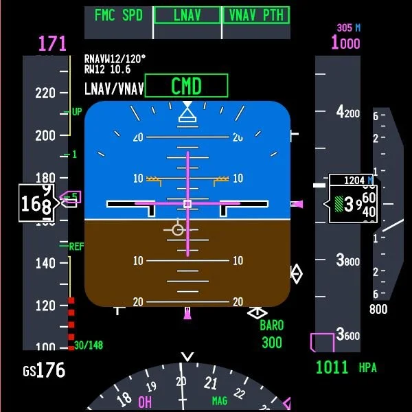
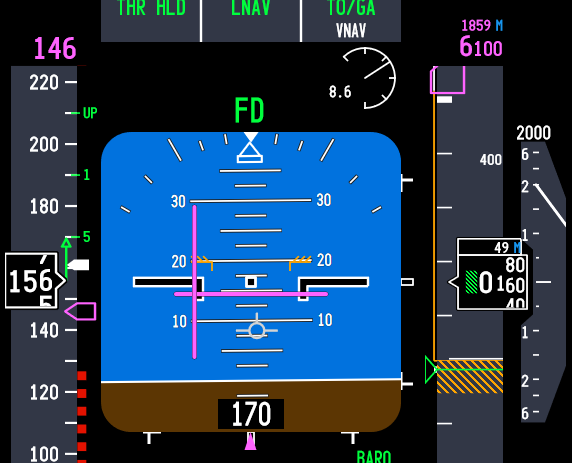
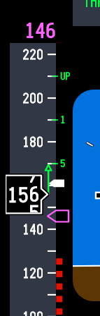
These references are displayed on the speed tape in the Primary Flight Display (PFD).
1: Minimum Manoeuvring Speed (Vmin)
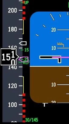
The minimum manoeuvring speed is shown by the green‑coloured numbers on the inner side of the speed tape. For example:
Green 1 is the minimum manoeuvring speed for flaps 1;
Green 5 is the minimum manoeuvring speed for flaps 5; and
Green 10 is the minimum manoeuvring speed for flaps 10.
These numbers represent the minimum safe speed for that flap setting and provide:
A stall margin;
A manoeuvring margin (~25° bank) 1; and
Gust and turbulence protection.
These speeds are computed by the FMC and vary with aircraft weight.
1: Operationally, many airlines teach 25° bank margin, but the certification basis for Vmin actually includes 40° bank capability.
Important Point:
At no point should the airspeed decay below Vmin without the appropriate flap setting being extended.
2: Amber Band (two bands - upper and lower)
On the Primary Flight Display, the amber bands on the airspeed tape indicate that the aircraft is approaching cautionary speed margins.
Upper amber band – approaching maximum operating speed.
Lower amber band – approaching minimum manoeuvre speed.
The bands are advisory. They provide a visual indication that the aircraft is approaching a region where the stick shaker, overspeed clacker, or buffet margins could soon be reached. Their visibility depends on the aircraft’s flap configuration and the operational phase of flight, such as takeoff, climb, approach, and landing.
The amber bands are displayed when the aircraft is operating near high or low speed cautionary margins.
Upper Amber Band
The bottom of the upper amber band indicates:
The maximum manoeuvring speed;
Approach to high speed buffet;
The placard speed of the next flap setting (flap retraction); and
Indicates when the aircraft is approaching the maximum safe speed for the current flap configuration.
Explained more simply, the upper amber line on the 737‑800 speed tape during descent with flaps extended is the flap overspeed (flap limit) indication. It appears when the aircraft’s airspeed is approaching the maximum allowable speed for the selected flap setting.
In short: The upper amber band warns the pilot they are getting close to exceeding the flap limiting speed for the flap position that is currently have selected.
Lower Amber Band
The top of the lower amber band is the caution / manoeuvre margin and serves as a dynamic, real‑time cue showing the aircraft’s proximity to stall speed. This band represents the zone between the minimum manoeuvre speed and the stall speed awareness band (the red and black band). If the aircraft’s airspeed decays into this band, the aircraft will remain above stall; however, its manoeuvrability (reduced manoeuvring margin) is compromised and the allowable bank angle is reduced.
The top of the lower amber band represents:
The top of band indicates minimum manoeuvre speed;
The lowest safe speed for the current flap setting (flap extension);
Provides 40° bank capability in 1g flight; and
Is inhibited on takeoff until first flap retraction or valid VREF entered.
The amber band is not a flap extension reference - it is a stall protection cue and the band must be treated as cautionary. In other words, it is preferable that the aircraft’s speed should not decay to a speed below the top of the amber band.
Loss of bank capability (lower amber band)
When airspeed is at the minimum manoeuvring speed for the selected flap setting, roughly 25° of bank is available without significantly reducing the stall margin. As airspeed decreases into the lower amber band, the safe bank angle typically reduces to about 15°. When approaching the bottom of the amber band, it decreases further to around 5–10°, depending on aircraft weight, turbulence, and other operating conditions.
This is because Increasing bank angle raises the aircraft’s load factor, which in turn increases stall speed.
If the airspeed is already close to the amber band, even a moderate amount of bank can push the aircraft’s airspeed toward the red and black band and stick shaker activation.
Important Point:
The Flight Crew Training Manual (Boeing, Flight Crew Training Manual (FCTM) (2024) notes that for operations other than LNAV, when operating at or near maximum altitude, crews should fly at least 10 knots above the lower amber band and limit bank angle to 10° or less. If airspeed drops below the lower amber band, the crew should immediately increase speed by taking one or more corrective actions.
- Reduce angle of bank;
- Increase thrust up to maximum continuous; or
- Descend.
3: Red and Black Band (Vstall)
The red and black-coloured band represents the stall boundary. If the airspeed decays into the red and black band, the aircraft is operating at or near the stall angle of attack. Stick shaker activation will occur when the aircraft’s angle of attack reaches the stall threshold.
4: Maximum Flap Extension Speed (VFE)
The maximum flap extension speed (VFE) for the Boeing 737‑800 defines the highest speed at which each flap setting can be safely selected without risking structural damage. Every flap position has its own VFE limit, and exceeding those limits can stress the flap system. The VFE for the 737-800 are as follows:
Flaps 1 → 250 kt
Flaps 2 → 250 kt
Flaps 5 → 250 kt
Flaps 10 → 210 kt
Flaps 15 → 200 kt
Flaps 25 → 190 kt
Flaps 30 → 175 kt
Flaps 40 → 162 kt
The VFE speed should be readily visible on a placard attached to the MIP below the landing gear handle.
What this means is that the pilot can extend the flap setting that is adjacent to the maximum speed, however, during normal operations, flight crews rarely extend flaps at VFE. Rather, they typically reduce speed to something closer to the UP speed on the speed tape and then begin to extend the flaps.
When To Extend Flaps
Expanding on what has been written, the flaps should be extended when the airspeed is below the maximum flap extension speed (VFE) and at or above the minimum manoeuvring speed (Vmin).
The correct technique is to select the next flap increment as the airspeed passes through the previous flap reference. For example, as the airspeed approaches or passes the flaps UP manoeuvre speed, select flaps 1; when the flaps 1 manoeuvre speed is reached, extend flaps 5.
It’s common practice for pilots to skip flaps 2 and go directly to flaps 5. Similarly, flaps 10 may be excluded (flaps 5 directly to flaps 15). The reason for this is that flaps 2 provides:
No operational advantage in normal flying and is mainly there for non‑normal procedures;
Abnormal flap conditions; or
Specific operator SOPs.
Similarly, flaps 10 provides no operational advantage in the standard approach profile. Flaps 10 is usually only used for:
Non‑normal flap operations;
Partial flap landings; and
Flap asymmetry or failure cases.
This said, in my experience using flaps 10 can offer benefits if ATC request a slow airspeed.
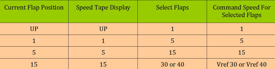
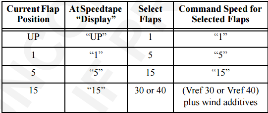
TABLE 1: Flap Extension Table. The table does not include flaps 2, 10 & 25 as these flap settings are often overridden to the next flap setting. © JAL-V
Manoeuvring Speed
Boeing recommend flight profiles should be flown at, or slightly above, the recommended manoeuvre speed for the existing flap configuration. These speeds allow full manoeuvring capability (25° bank). (Boeing, Flight Crew Training Manual (FCTM) (2024).
Important Point:
Selection of the flaps to the next flap setting should be made when approaching, and before decelerating below, the manoeuvre speed for the existing flap setting (Boeing, Flight Crew Training Manual (FCTM) (2024).
Speed Trend Vector
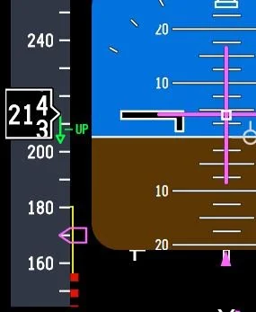
When the aircraft’s airspeed is increasing or decreasing a green-coloured upwards or downwards facing arrow is displayed on the speed tape. This is called the speed trend vector. The arrow indicates the predicted airspeed in the next 10 seconds based on the current airspeed and acceleration / deceleration rate.
The speed trend vector can be very helpful in gauging the correct time at which to extend the next increment of flaps.
Flap extension is not instantaneous, and depending on the selected setting, it can take several seconds for the flaps to transition between increments. Because the downward facing trend arrow shows where the airspeed will be in approximately 10 seconds, it can be used as a rough reference for timing the next flap selection. In practice, the next flap increment should be initiated as the trend arrow is close to or at the minimum manoeuvring speed (Vmin) reference 2.
2: This technique is not published by Boeing, but is a useful technique that pilots often use.
Important Points:
Correct management of the flaps is selecting the next lower speed as the additional drag of the flaps begins to take effect.
If consideration is made toward when the flaps are extended, the transition between flap increments is relatively smooth.
Final Call
This article has explained the key references used to determine when to extend or retract the flaps. By following the recommended flap extension and retraction speeds and maintaining the correct airspeed, the aircraft remains within its certified limits and each configuration change occurs in a controlled manner. When the procedure is followed as intended, flap transitions remain smooth and the aircraft maintains a stable, well managed approach profile.
BELOW: Images showing the various display references discussed above:
The minimum manoeuvring speed (green-coloured numbers);
The amber band (upper and lower)
The red and black band; and
The speed trend vector arrow.