Belkin Hubs - An essential Add On


BELKIN powered hub with external case removed

Throttle Commands Not Working

Refurbishing a throttle quadrant is not without its problems.  In an earlier post, I touched briefly on the issue of the throttle commands not responding.  The connection between flight simulator and the throttle would drop out and anything related to the throttle quadrant would cease to function.

Determining the problem was time consuming, however, the culprit was a faulty power supply that powered a Belkin USB powered hub.  The power supply I had been using was a standard computer power supply unit (PSU) and it was not new.  The PSU was overheating, and when it reached a particular temperature it would cause the powered Belkin hub to disconnect.  When the PSU returned to normal temperature (after being turned off) the Belkin hub worked perfectly.

USB Hubs - always use a powered hub

Hubs are an important piece of gear when putting together a simulator or running anything that has a lot of peripherals.  Unless you have a city of USB ports on the rear of your computer (unlikely) then you will need a hub.  Hubs are good as they minimize the number of USB cables that need to be connected to your computer.

When selecting a hub only use a powered hub. The reason being is that there is often a lot of information being transmitted, via the hub, between your device and the computer.  A powered hub helps maintain the integrity of the hub and stops information drop outs.  I only use non-powered hubs for devices such as keyboards and mouse.

Phidgets and Hubs

I learned from experience (computer crash & scrambled phidgets) that it is not a good idea to connect phidgets directly to your computer via the USB cable.  I'm not exactly sure why this is not possible, but it is recommended on the Phidget forum to always use one or two powered hubs when connecting phidgets to your computer.

Outstanding Service - You Tell Me....

Christmas and New Year is the worst time for anything technical and complicated to arrive - period.  Stores close, technicians take vacation, and managers and owners hide from the public.  For many, Christmas is a religious and/or festive day.  For most, it's a time to escape the pressures of work and relax with friends and family.

Software Installation & Configuration Questions

It was a few days before Christmas Day, the MIP had arrived a few days earlier. For some reason I couldn't get the FDS software to function correctly, I didn't have a registration key to unlock the software, and basically was a little clueless on how to get this animal moving! 

Several e-mails had transpired between Flight Deck Solutions and Sim Avionics - but it was slow going.  I was keen to get the basics set up so I could navigate through the various configuration options during the Christmas week.

Then, on Christmas eve - 2130 Canadian time my cell phone rang....  "Hi this is Peter Cos from Flight Deck Solutions, I hear you have a problem!  I can sort this out for you quickly.  I realize there are many systems to get in place and your feeling overwhelmed at the moment - no problems.  Let's work through each issue in turn and get you flying"  

From this post, you may think that the configuration of FDS and Sim Avionics software is difficult; this is far from the truth.  Once you are steered in the right direction, have the correct folder structure established on your computer, installation is very straightforward. 

Now, for those who are really bored and have read through this website in entirety, you may remember that one of the reasons I bought from Flight Deck Solutions was because of the backup service.  Tell me - what better service can you expect when the owner of the company rings you, from the sidewalk outside a restaurant in Canada, to try and solve your issue......ON CHRISTMAS EVE!

Following this phone call, I received prompt e-mails from Mark Hastings (United Kingdom) and Nat (Australia).

Thank you Peter Cos, Steven Cos, Mark Hastings and Nat for your time and patience.

  • All the issues were solved over the next few days via e-mail and telephone calls.

UPDATE - Progress Report

primary flight display sim avionics

Well, Christmas and new year has passed and I'm still working on the simulator.  There have been some niggle-like teething issues that every infant must succumb to.

Faulty Power Supply

A problem developed with the throttle quadrant which had me baffled for several hours (read days).  The throttle quadrant would stop working or some of the controls/commands would give spurious results.  Was it incorrect FSUIPC offsets or was it dodgy wiring or loose connections (?).  I went through the construction and set up with a tooth comb.  Then the solution was found.  It was a power supply which was powering the Belkin hub that a few of the USB cables were connected through to the computer.  I noticed the power supply was quite warm and getting warmer, then it would just stop working to begin working again when it cooled. 

Replacing the power supply plug seems to have solved the issue.  This said, I'm a little wary of running too many important USB connections through a hub.  Therefore, tomorrow I intend to add another row of USB interface connectors to the motherboard and maybe an additional powered hub to help share the load.  One important snippet of information important to know when using Phidgets is NOT to connect them directly to your computer.  They should be connected to a powered hub (this comes from the Phidget forum).

Sim Avionics

As you know the MIP has arrived as has Sim Avionics and some other assorted software.  Everything is installed and I'm going through a learning stage with correct software set-up and operation.  It takes considerable time testing to ensure the best set-up.

Sim Avionics is complex, but no unfathomable.  The interface is very clean and very easy to use once set up correctly.  Currently, I've been put to the test remembering (or learning) flight operations that either I have forgotten or never knew!  A quick glance at the PFD display will give you a idea what this beast is capable of - amazing stuff when you think about it.  Reading, learning and asking questions takes time!

I'll put together a basic report on the MIP, CDU and Sim Avionics software in a few weeks time - once I've got a good handle on its functionality.

MCP Issue

The MCP I am using is produced by CP Flight in Italy.  For the last two weeks or so I've been struggling to get the MCP to connect correctly to flight simulator.  After in-depth testing with CP Flight and others, CP Flight have asked that I return the unit for replacement.  Over the years I've used many products from CP Flight, and for the most part all there products are exceptionally solid and robust.  Hopefully a replacement unit will soon land in Australia as flying using a virtual MCP isn't exactly easy and fun!

Other than this, I've been touching up some painting, cleaning up the wiring, fabricating two side panels to fit between the throttle quadrant and the front of the MIP and a few other bit and pieces here and there.

Installing Display Monitors to Flight Deck Solutions MIP

fds mip. the mip has a very handy shelf at the rear. propriety angled monitor display stands are very helpful in securing monitors to the rear of the mip. When positioned correctly, the bracket is tightened with Allen bolts

Over Christmas, I mounted the display monitors to the MIP.  Although an easy task, it’s a bit fiddly trying to match up the monitor display with the perspex panel in the MIP.

Monitor Display Stand

double sided cushion tape is used to frame each monitor. this avoids dust and stray light from entering the side of the monitor

I’m using two Viewsonic 19 inch wide screen monitors for the primary flight display and navigation display and an older HP 15 inch monitor for the centre EICAS.  After dismantling the plastic covers from the displays (how these clip together without screws only the Chinese can manage), I cleaned each screen before fitting to the rear of the MIP.  I’m glad I purchased from Flight Deck Solutions the monitor display holders, which make the attachment of the displays so much easier.  It’s only a matter of acquiring the correct position of the display, then moving the cradle forward, back, left or right and tightening the Allen screws.  It's a simple install and adjustment, but as mentioned, does take some time to ensure the screens are mounted in the correct position.

Concerned About Dust

I was concerned that dust and back light may stray onto the monitor display between the display and MIP Perspex.  This is because the lower side of the monitor does not sit entirely flush to the perspex.  I solved this potential issue by adding to each monitor frame a layer of adhesive padding.  The padding also provides a soft interface between the front of the display and the MIP.  The padding strips are readily available at hardware outlets and often are used in the fitting of glass shower screens.

I couldn't find black coloured adhesive , therefore, to minimise the chance of seeing the white adhesive, I used a permanent marker pen to colour in the inner edge.

One important thing to note when installing the displays is to make sure they are orientated the right way!  I installed them upside down – maybe because I live in Australia :)

Clean Up Wiring

Next on the list is to clean up the wiring from the MIP to the two computers.  As you can image there are a lot of wires, USB cables, power and monitor cables.  I used a wiring loom to keep things somewhat tidy; I dislike “rat-nest” wiring. 

What's Next?

After this, it’s onto installing Sim Avionics and other FDS software to get the MIP operational with full functionality. 

Installing Weber Pilot Seats to Platform Base

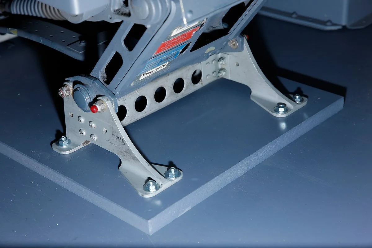
oem 737-500 weber claw feet and platform mount

The Main Instrument Panel (MIP) is an integral part of the flight deck.  Now that it is installed, other components can be measured and fitted to the floor platform.  I wanted to install the eats correctly, even though the platform is a interim platform and will be replaced with an aluminum box platform sometime in the future,

The two Weber seats would take considerable time to attach to the platform, as unlike Ipeco seats they do not use a J-Rail system, but use claw feet. The feet must be positioned correctly onto the platform floor.

Attachment Stress

oem weber seat mechanism

In my earlier posts, I mentioned that to manipulate the various levers which move the seats results in relatively large amount of stress being placed on the attachment points of the seat to the platform floor; there is reason Weber seats have 16 attachment points to the flightdeck floor. 

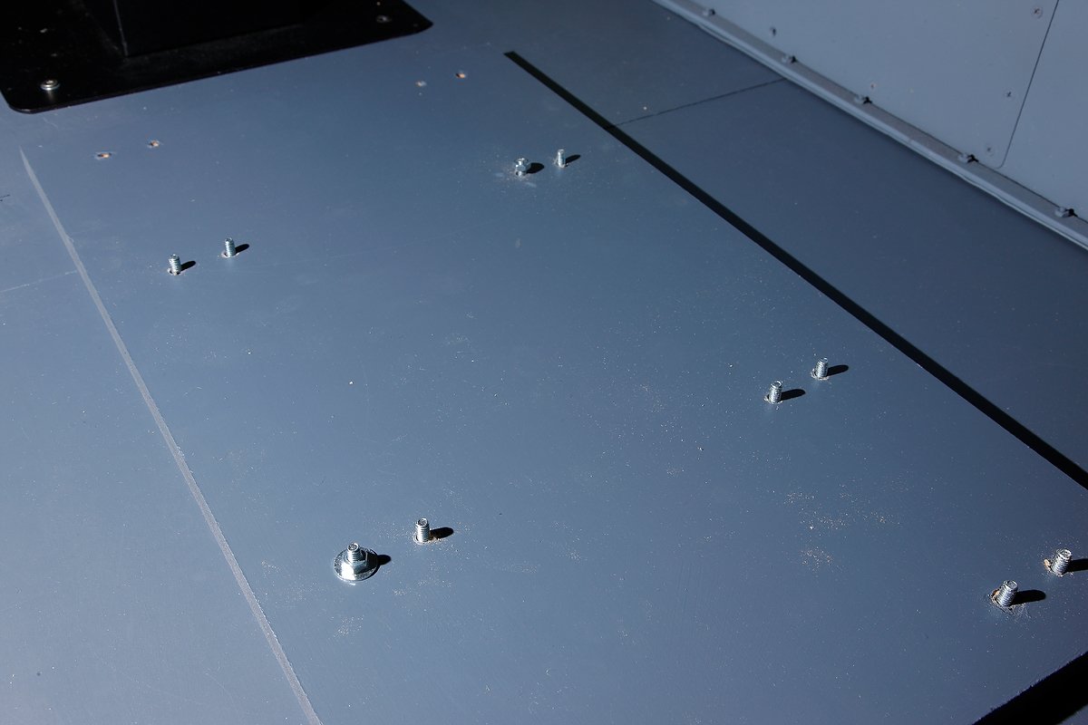
To minimise the chance of the seat moving when adjusted, I fabricated a mount that sits beneath each seat.  The mount, constructed from wood, is 16 mm in thickness and is bolted to the 16 mm thick platform floor (36 mm total thickness).  Rather than use wood screws to attach the seats, I decided to use 55 mm length bolts with washers; my thinking is that the bolts will provide far stronger attachment points, when installed through the seat mounts and platform floor, than wood screws. 

Attaching the Seats

The first task was to cut and paint the seat mounts which was straightforward. Each seat was then attached to its mounting base and then secured to the platform in the correct position with bolts. The biggest problem was actually lifting and moving each seat into position on the platform, each seat and segment of flooring weighs over 50 kg.

Correct Positioning

The correct positioning of the seat and seat mount is very important.  Boeing specification states that the distance from the front of the seat to the MIP is 340 mm, however, this depends on where you are measuring to and what type of MIP you are using.  The measurement if using a FDS MIP is from the front of the claw feet to the forward edge of the lower kickstand.  This measurement is 440 cm.

wooden platform mount connected to claw feet of weber seat. the seat and mount are them positioned correctly on the platform and secured using bolts

The seats move forward and aft, by pivoting over the secured claw feet (see video); therefore, if the measurement is out by a cm or so it is not really an issue as the seat movement can take up the difference. 

It Works….

With the platform floor secured to the base it was time to trial the seats.  Both seats work well and there is no movement or flexing at their attachment points.  There is also no movement where the seat mounts join the platform floor.

I think it was overboard using 16 bolts and bolting through 36 mm of woo!  But, I wanted to make sure the seats did not move on their base as I didn't particularly want to remove them and start over again. 

Next on the list is installing the ACE yoke and throttle quadrant.

The wooden platform has since been replaced with a modular aluminum structure.

Installing the ACE Yoke & 737-300 Throttle Quadrant

ace engineering 737 yoke

ACE Yoke & Column

Now that the seats are attached, it’s time to secure the ACE yoke to the Captain side of the flight deck and then secure the throttle quadrant and center pedestal to the floor. 

Attaching the ACE yoke is straightforward; measure correctly against the MIP the spacing as per the Boeing specifications and attach with four screws – presto!

Throttle Quadrant

Ace engineering 737 yoke and column

I am hesitate to secure the throttle quadrant to the floor until I am very sure that the wiring is correct and everything functions.

Throttle Quadrant Does Not Sit Flush

The throttle quadrant does not sit flush with the MIP, the later having an angled front while the quadrant is a straight 90 degree angle.  I want to fabricate two angled side walls to cover this open space so you cannot see the wiring at the front of the quadrant.  I'll fabricate these panels probably from Perspex or MDF wood and paint in Boeing grey or stark white.  They will be screwed in place and be easily removed for wire maintenance (if necessary)

oem weber seats, 737-300 throttle quadrant and two bay center pedestal

I also want to determine how much the throttle moves when the trim wheels rotate; this will determine how and where I secure the throttle quadrant to the floor structure. 

Maintenance

Everything may be functioning on the throttle quadrant now, but in 12 months time it may be different. Maintenance is an ongoing task with anything that moves; therefore, it is important to enable easy access to wiring, etc. At some point the throttle quadrant may have to be removed from the platform, and the method used to secure the quadrant must facilitate easy removal.

Slowly Taking Shape

It's has taken some time, but the simulator is now beginning to look like a simulator rather than a room full of aviation junk.

Main Instrument Panel (MIP) Arrived - Updated Progress

fds mip in a large crate in trailer

At last, a phone call from DHL Freight Forwarding has advised me that the Main Instrument Panel (MIP) I ordered from Flight Deck Solutions (FDS) in Canada, in August, has finally arrived and is ready for pick up.

This means that the next phase -  the actual construction of a working sim can begin in earnest. 

The box that is used to transport the MIP is large as the MIP is prefabricated. When you order a MIP from Flight Deck Solutions you can choose to have it flat packed or prefabricated; I choose the later.

To recap on what has been achieved since August 2010:

  • Research, ordering and implementation of project

  • OEM 737-300 throttle quadrant overhauled and converted to operational use with flight simulator (FSX) & troubleshooting completed

  • Several phidget cards installed and calibrated to correct operation

  • 737-300 center pedestal overhauled and ready to populate with avionics modules

  • Platform base constructed and painted

  • Weber Captain and First Officer seats procured and overhauled to working order

  • ACE yoke & column purchased, calibrated and flight tested

  • OEM 737-500 yokes and columns procured and awaiting conversion to operational use in flight simulator (March 2012)

  • Computers purchased, configured and networked

  • MCP and EFIS (pro version) purchased from CP Flight in Italy

  • Avionics modules (various) purchased for installation to avionics bay and evaluation

  • Main Instrument Panel (MIP) wired and prepared for installation and evaluation

  • Various genuine B737 instruments procured and awaiting conversion to operational use in flight simulator (in due course)

  • various software add on packages purchased and evaluated

Therefore, everything appears to be ‘green for go’.

Weber Seat Mechanics - They Are Built To Last

The under seat workings of the Weber seat: Heavy duty chassis, the smaller of two heavy duty springs, two of three cables and the cylindrical hydraulic/pneumatic cylinder

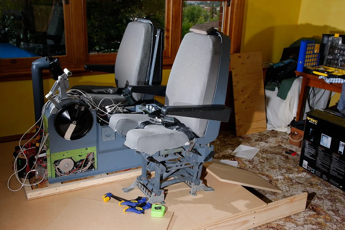
In a earlier journal post (Weber Captain & First Officer Pilot Seats), I discussed the purchase of two Weber pilot seats.  What I didn’t discuss was how these seats function.  Weber seats, although constructed from aircraft rated aluminium are not light in weight; each seat weighs approximately 40 kilograms.  Most of the weight is associated with the robustly constructed underside the seat.

The seat has four movements:

  • Forward and aft movement;

  • Vertical rise;

  • Recline of back rest; and,

  • Under leg rise & fall.

Mechanics

Each movement is initiated by moving one of three solid lever on the pedestal side of the seat.  The lever operates a push style button connected to the end of a cable.  As the lever is moved the button is pressed or released with a corresponding press and release from another button at the opposite end of the cable.  The compression needed to allow these movements is controlled is by a very heavily constructed tensile spring that is contained within a cylinder.  This in turn is connected to a hydraulic/pneumatic piston that allows for greater ease in movement.

The mechanics control the subtle movement of the rear seat recline (like in an automobile) and the under leg rise and fall of the portion of the seat, that can be raised under the calves to allow more or less reach to the rudder pedals.  When the desired position is reached and the lever released, a heavy duty ratchet / cog is engaged locking the position in place.

The two most aggressive movements of the seat are the forward and aft movement of the seat and the vertical rise. This and the non use of J rails are two reasons that Weber Seats are attached to the flightdeck floor by 16 attachment bolt points by eight claw feet (duck feet) for each seat.

Weber manufactures a number of different variants: hydraulic, electric, spring or a combination thereof – there are several variations in use throughout aircraft fleets. The seats I am using are spring and hydraulic controlled. 

ACE B737 Yoke & Column - Review

I purchased a pro model B737 yoke and column from Ali at ACE Engineering (Aircraft Control Engineering) in Canada to use as a fill-in until I found a pair of real B737 yokes and columns.  I wasn’t to realize at the time of my order, that I would discover a quality pair of columns a few weeks later!

I’ve received a few e-mails asking about the yoke and column; therefore, I thought I’d post a quick review.

General Overview & Rating

This is a nice yoke and column that has been designed well and constructed of quality materials.  The set up and configuration is very easy and straightforward.  The operation of the yoke and column is very good in comparison to less expensive products such as CH Products, and is as good if not better than their nearest competitor which is Precision Flight Controls.  The only draw back, other than slow e-mail communication with the supplier, is the poor quality of the bank decal on the elbow, and the lack of a solid and heavy base for those who do not wish to secure the yoke directly to the floor. 

My rating: 8/10   (due to lack of a heavy base plate & poor decals)  

If I wasn’t going to be using a genuine B737 yokes and columns, then this is the product I would use long term.

Ease of Ordering, Packing and Incomplete Parts

Ordering the yoke was fairly straight forward and payment convenient as Ali accepts Pay Pal.  Communication with Ali was very sketchy and often I would have to send two or three e-mails to receive a reply.  I have no idea why this is the case, but I believe Ali is a “one man band” so it’s understandable that he cannot do everything and be everywhere at the same time – even with the wonders of wi-fi and i-phone4!  

The time from ordering to receipt was around nine weeks.

The yoke and column arrived in Australia is a largish plywood box securely packed in a contoured foam mould; I was impressed with the security and simplicity of packing.  The foam mould held the column and yoke securely and no movement was noticeable.   Unfortunately, Ali failed to include a USB cable in the box so I had to purchase one separately.  Although a small item, I consider that one should have been supplied considering the high price of the yoke.  Likewise, Ali failed to include the chart holder and rubberised grommet cover for the yoke.  I contacted Ali about these items, but after four weeks have yet to receive them.

Construction

The design and construction of the yoke is above par.  There is absolutely no way that the Aces product can be compared with products produced by CH Products or similar.  I’d say the construction and quality is on a par with Precision Flight Controls (PFC) but less than an OEM 737 yoke (obviously).

The column and stand are constructed from machine grade aluminium and powder coated in the correct Boeing colours.  The yoke is constructed from a solid piece of aluminium, powder coated in black with a glossy plastic finish.  The yoke has a very solid feel to it and it’s obvious that this is not a toy.  The buttons and switches on the yoke all appear to be of high quality and the electric trim switches replicate the Boeing style switches.  On the right hand side of the yoke (Captain’s side) there is rubber grommet that can be easily removed to install a trip indicator.

A problem I noticed is that the base plate is made from very thin anodized aluminum; it is lightweight and has a small surface area.  The plate required a secure attachment to stop movement of the unit.

For convenience, I’ve transcribed a copy of dot points from the Aces website below:

  • Accurate replica of 737 series Yoke.  

  • Full metal and Aluminium casting.  

  • All Aluminium Yoke Handle.  

  • Realistic tension loading.  

  • Realistic Aircraft Feel.  

  • Screen-Printed lettering on Yoke.  

  • B737-NG Clipboard for reading Charts. (Included at no extra charge)

  • Trim switch based on SAAB model.  

  • Two 737 NG push to talk (mike button).  

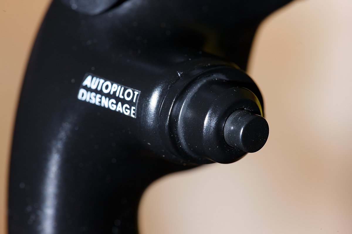
  • 737 Autopilot Disconnect button.  

  • Button inputs can be assigned within the flight simulation assignments  

  • Mil-spec potentiometers for durability and spike free operation.  

  • Not susceptible to drift requiring re-calibration.  

  • Full Speed USB HID compliant device. Works with USB 2.0 compliant system.  

  • 12-Bits resolution (4096 steps)  

  • Hardware calibration support. No calibration in Windows required.  

  • Axis trim and dead zone settings  

  • User adjustable digital filtering algorithm support  

  • Firmware updates via USB  

  • USB bus powered

Set Up

Set up is exceptionally easy.  I’m using a computer running Windows 7 64 bit and the yoke was immediately recognised by the computer software.  Opening the settings tab in FSX you can see the Ace's yoke software interface.  To configure the yoke, it’s only a matter of assigning button presses and calibrating axis movements.  This can either be done within the Ace joystick controller/button assignment software or via FSUIPC.  Everything was very straightforward and remarkably easy.

Functionality and Operational Use

What can I say – the yoke works as it’s designed. 

If you are used to a desktop push and pull yoke then the movement of the column will feel odd for a short time.  The ability for the yoke to center detente is controlled by springs, while the dead zone is controlled by software configuration.  Now and again you can hear the springs move as they replicate the pressure of a simulated real yoke, but this is completely normal when using heavy springs to control back pressure. 

The pressure generated by the springs is nowhere near that of a real 737 aircraft, but for many this is not an issue.  The yoke and column move very smoothly in the forward and aft movement; there is no jerkiness that is associated with other yokes and columns.  However, in roll mode the yoke is not as smooth as I would have thought; slight jerkiness is experienced in the first 5 degrees of roll.

The yoke’s angle of incline matches fairly closely the degrees of bank measurement as indicated on the decal.  If this isn’t satisfactory, then detailed calibration can be completed in the FSX setup area and/or via FSUIPC (strongly recommended).

I have only used the product for a few hours, so I cannot comment on the longevity of the product.  Ace have used military specification potentiometers for durability and spike free operation, so I assume durability is medium to long term.

Problems

There is very little to complain about, however, if pressed, there are three things:

The decal which indicates the angle of bank (on the upper section of the column elbow) is of low quality.  Within a few hours the decal had begun to peel away at the edges.  You can note the decal separating from the elbow in the first photograph.  I believe a silk screened decal, similar to that used on the OEM yoke, would have been a better and more permanent option. The other yoke decals are satisfactory.

Second, the stand which supports the column and yoke is very light weight.  If you place your yoke and column on a carpeted floor and attempt to use it, you will find it will slide very easily.  The plate needs to be attached securely to a platform base, floor or other structure to stop this movement.  There are four holes fabricated into the base plate to allow for this attachment. 

Third, as discussed above, the yoke when tuned left or right (roll mode) is not as smooth as I would have expected and feels a little jerky.  This is more evident in the first 5 degrees of roll.  I have checked with other users and they claim this also occurs with their yoke.

737 Trip Indicator

The trip indicator is a three digit, back-lit dial that can be fitted to the Ace yoke - it is an OEM item.  The Ace yoke has a rubber seal covering the hole where the indicator resides.

The hole is slightly too small to accommodate the OEM trip indicator and will need to be enlarged a few millimeters to enable the indicator to be pushed into the hole.  The actual depth of the indicator is not cause for concern as it sits flush to the front edge of the yoke.  To read about Trip Indicators.

Affiliation

I have no affiliation with this product or any other product I discuss on this website.

Update

on 2012-10-27 10:41 by FLAPS 2 APPROACH

Chart Holder - Finally Arrived

Completing my order with Ali was a nightmare.  Although he eventually responded to my several dozen e-mails, the promised chart holder did not arrive.  Eventually, almost one year to the day that I received the yoke, the chart holder arrived. Oddly it was sent to me by one of Ali’s customers in Australia (who had purchased a yoke).

Although conjecture, I believe Ali did not want to pay the shipping cost to send the missing chart holder to me, which is why he piggy-backed the item on a yoke shipment to another person in Australia.  To Ali's credit, he did reimburse the internal postage that I paid to have the other person send the chart holder to me.

The quality of the chart holder is very good and I have no problems with the holder, although I do not have a OEM chart holder to make a direct comparison.

Update

on 2013-04-08 01:42 by FLAPS 2 APPROACH

The Ace Engineering yoke has been sold. I am now using an OEM 737 yoke and column.

There is absolutely no comparison between a reproduction part, no matter how good it is, and the OEM counterpart.  The genuine item has been made to exacting requirements, has been built to withstand frequent abuse, and is designed to provide longevity.

Aesthetically, both the ACE and OEM yoke look similar, however the feel is completely different.  The electric trim switches on the genuine yoke feel more solid and robust and less toy like.  The buttons also feel more robust with a more hefty push required to activate them. 

Functionally, the OEM yoke has a much silkier and smooth feeling when rotating the yoke.  There is absolutely no binding that is readily apparent when using the ACE yoke (when turning the yoke approximately 5 degrees bank).

The ACE column does not attempt to replicate the OEM control column.  The OEM columns have a bulbous lower section that must be fitted into the flight deck floor and then linked to the column on the First Officer side.  The ACE column terminates in a flat plate that is screwed to the floor. 

This said, the ACE yoke is probably one of two yokes and columns that are currently on the market that come close to a genuine yoke; the other is produced by Precision Flight Controls in California.

Navigate to 737 yokes and columns to read more about the OEM control columns.

Weber Captain & First Officer Pilot Seats

weber seats on trailer

A call from DHL Freight logistics alerted me to the fact that another large crate had arrived at the local airport for pick-up.  It was too early for the consignment to be the MIP, so the next contender was cockpit seats.

I wasn’t going to purchase pilot seats until the project was nearing its final phase.  However, genuine B737 seats are becoming more difficult to find in good condition, and when I was offered these seats, I decided to purchase them. 

Boeing aircraft use for the most part two types of aircraft seats: Ipeco and Weber; the former being the more modern seat design with adjustable J-rails.  Personally, I find the Ipeco seats to be rather uncomfortable and the configuring of J-rails can be painful.  Weber seats bolt directly to the floor, so as long as you have the correct measurements for the bolt down locations, there shouldn’t be any further problems.  Both the Ipeco and Weber seats have several seat levers to allow for correct and comfortable positioning.

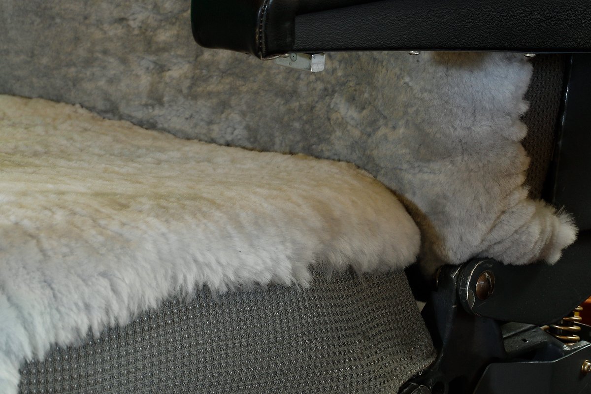
Weber seat cushions are either manufactured from cloth, which are the seats I have, or they have sheepskin covers sewn over and into the cloth.  At some stage in the future, I may have sheepskins installed over the seats, but at the moment this is a secondary issue.

Apart from some very minor cosmetic issues associated with the plastic molding on the rear of one seat, both seats are in excellent condition.  You have to remember that seats are always in used condition and probably have flown thousands of hours.  Before their new home in the simulator, they were fitted to a 737-500 series aircraft belonging to South West Airlines. 

Minor Overhaul of Flight Officer Seat

Although cosmetically the seats look OK, the right hand seat (flight officer) didn't seem to be operating correctly.  Inverting the seat, I was shocked to see a built up of dirt, grim and dust over the mechanism that controls the movement of seat.  Disassembling the components, I also discovered a broken split pin which was stopping the connecting cable, which controls the vertical rise in the seat, from working.  After cleaning and replacing the broken split pin, I lubricated all the areas requiring lubrication.  PRESTO, the seat now works as it should.

Leg Attachment Points - Four Seat Movements

Each seat has 16 attachment points to secure the seat to the floor.  One reason for this is that when you alter the position of a Weber seat, especially forward and aft, the pressures exerted on the seat legs are very high.  The seat has four movements: back reclining (like in a motor car), vertical rise (upwards lift of about a foot or so in height), under leg lifting and forward and aft seat control.  The last movement is needed as Weber seats do not use rails.

CASA Approved?

I was inspecting the seat feet (called duck feet because of their shape when my wife came into the room - she commented ’I hope their CASA approved’.  The first snipe - no doubt more will come  :)  I dare not try the seat harness.... (CASA is the Civil Aviation Safety Authority in Australia)

Oh and before you ask - yes the seats are very comfortable.

DZUS Fasteners

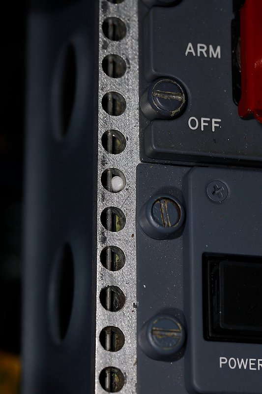
OEM DZUS FASTENERS AND RAIL

When I became interested in constructing a simulator, I heard knowledgeable people stating DZUS this or that - I had no idea what these individuals were referring to, let along how to pronounce the word.

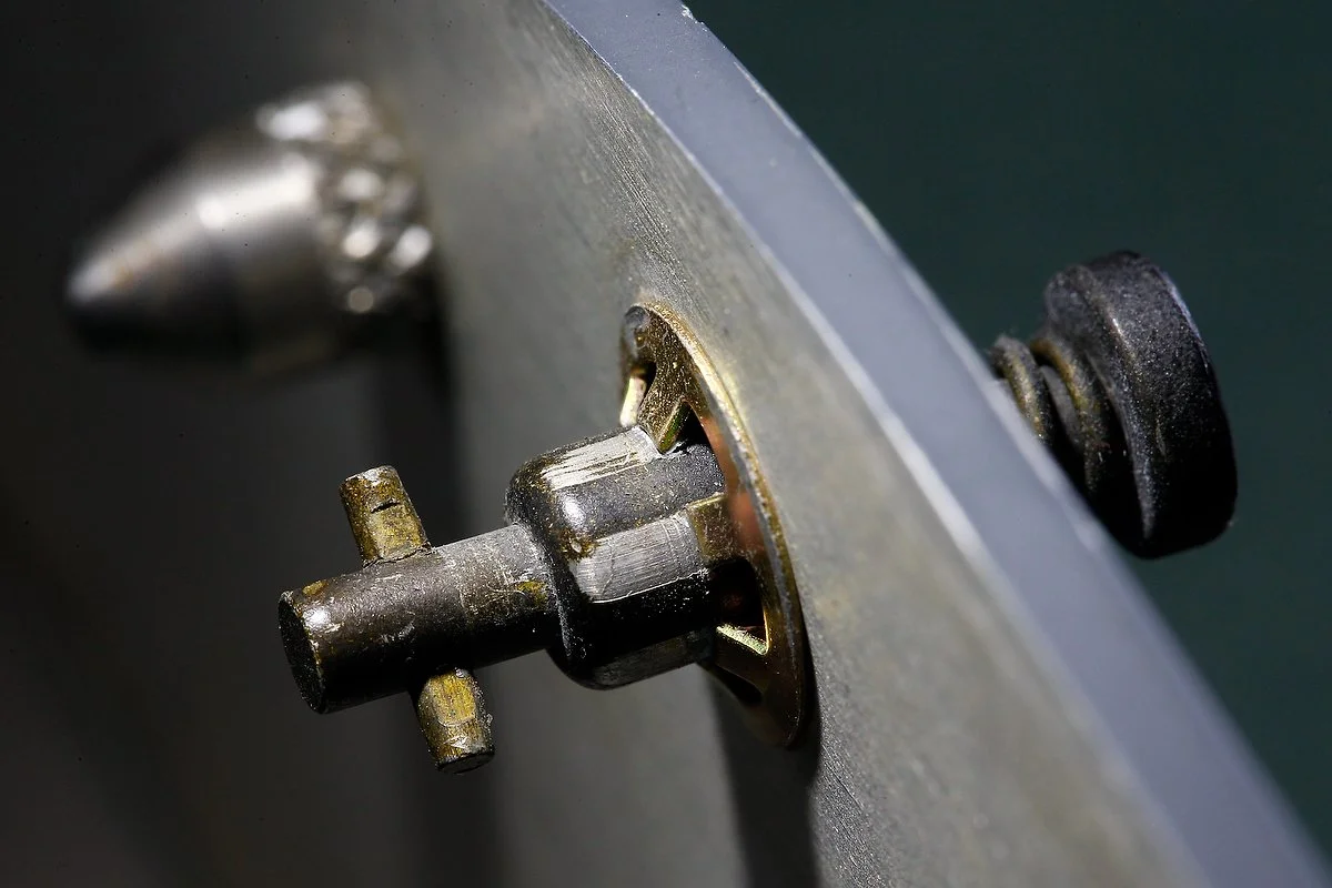
Dzus (pronounced Zooss) is a proprietary name for a type of quarter-turn fastener often used to secure skin panels on aircraft.

It was invented and patented by a native Ukrainian William Dzus (Volodymyr Dzhus) in the early 1930s. Quarter-turn fasteners are used to secure panels in equipment, airplanes, motorcycles, and racing cars that must be removed often and/or quickly. These fasteners are notable in that they are of an over-center design, requiring positive sustained torque to unfasten. A DZUS fastener will correct itself rather than proceed to loosen as it would in threaded fasteners.

Real DZUS Fasteners

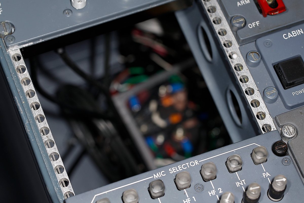
Finding individual real DZUS fasteners can be difficult as they are mostly attached to avionics panels, and the vendor wants to keep them with the panel. If you search long enough, eventually you will find an aviation scrap yard that has them available as separate units. I recently saw several selling on e-bay quite cheaply. I have a small collection of grey, black and bare metal coloured fasteners in varying condition, obtained from a scrapped Boeing 737 (I bought them in a 30 piece lot). The fasteners are needed to lock down any avionics panels to the DZUS rails of the OEM center pedestal and overheads and some panels in the MIP.

Reproduction DZUS Fasteners

If you’re using a OEM center pedestal with a DZUS rail, reproduction panels such as those produced by CP Flight or SISMO will not be able to secure to the rail easily. You will need to enlarge the circular hole along the edge of the module to allow the real DZUS fasteners to fit easily and correctly. If you decide to do this, be mindful that you don’t damage the edge of the module when you enlarge the circular hole. I used a titanium drill bit and carefully secured the panel in question in a vice on a workshop bench (wrapped carefully to avoid the vice jaws damaging the module) before drilling.

If you have replicated the center pedestal from MDF or wood and want to use something more realistic than boring screws to attach your panels, you can purchase after market'look alik’ DZUS screws. Basically these are wood screws with DZUS style heads on them. Good quality aluminium DZUS screws can be purchased from GLB Flight Products. I’ve used these on my earlier generic flight deck and they work very well and look just like the real ones…

Acronyms

OEM - Original Equipment Manufacturer.

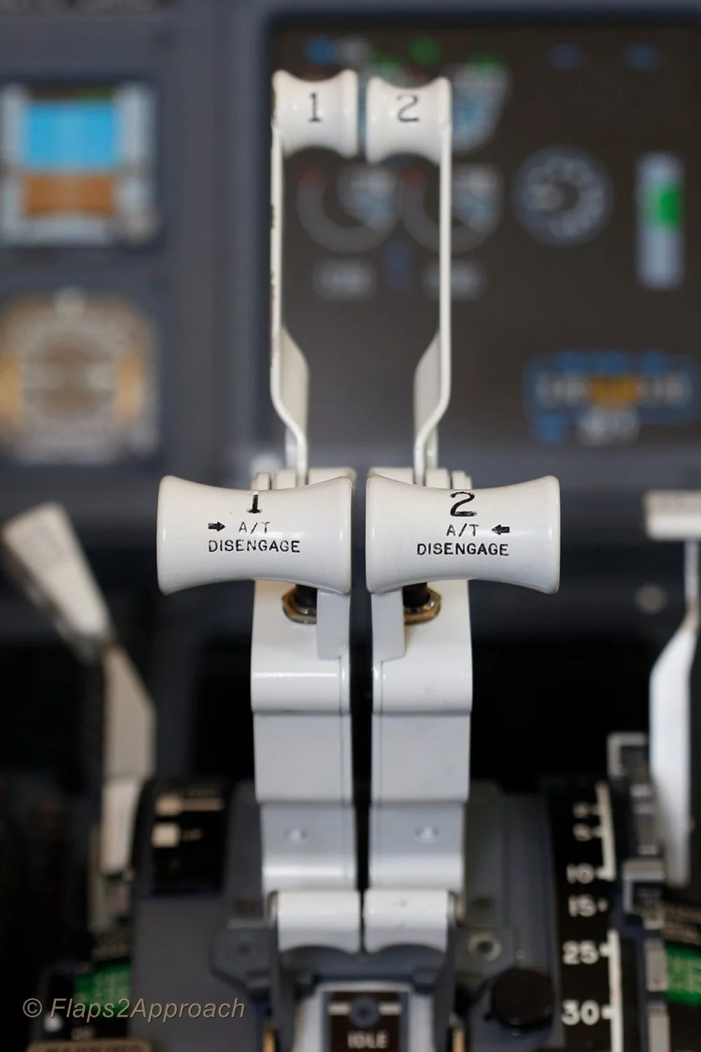
Sticky Autothrottle Button - Repaired

oem autothrottle button. note the circular circlip

I noticed soon after the throttle quadrant arrived that the engine number one auto throttle button was a bit sticky.  Depressing the button, it would stay pressed in for a few seconds even though pressure had been released.  The autothrottle buttons are one-way buttons meaning that they are click buttons.  It’s probable that after many hours of service, sweat, dead skin cells and dirt has built up on the inner button behind the spring mechanism; a friend suggested that DNA analysis of the built up debris would probably provide a list of suspect pilots!

Whilst the button was still in place, I attempted to loosen the built up material using a can of pressurized electronic cleaner fluid.  The fluid, I hoped would dislodge any loose material before evaporating.  Unfortunately, this didn’t work in the long run, although once lubricated with the evaporate solvent, the button operated correctly for a short time.

oem autothrottle button removed

Circlip

The button is held in place within the throttle handle by a ½ inch circlip.  Beneath the circlip and button there is a spring mechanism that pushes the button out after being depressed.  Using a pair of circlip pliers, I very carefully removed the circlip making sure that the spring mechanism of the circlip didn’t propel my button out the window and into the garden! 

With the circlip removed, the inner portion of the throttle handle slides out revealing the button and attached wiring.  The button is a modular design (shaped to fit inside the throttle handle) and unfortunately cannot be disassembled further, Therefore, I reassembled the button and sprayed a small amount of silicone spray around the button, allowing the silicone solution to penetrate around the edge of the button. 

The silicon lubricant (which is non conductive, so there is no issue with power shorting) seems to have solved the problem as the button no longer sticks, however, this is only an interim solution.  I'll search for a replacement button module.  Sometimes the most simple solution will fix your problem.

No doubt I can purchase a new replacement from Boeing for err $800.00....  I think not.  Eventually I'll find a disused button module in my travels.