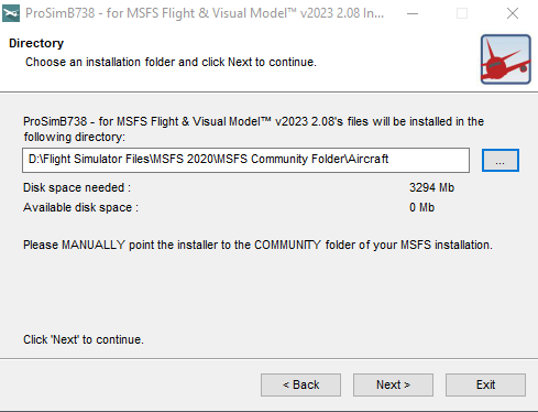
Installing the Navigraph Database to ProSim-AR (ProSim737)

No matter which avionics suite is used, the navigational database and approach charts will need to be kept up-to-date.  Navigraph (the company) have for many years been the mainstay in supplying accurate navigational data to the flight simulator community.

The navigation database and monthly updates can be downloaded from the Navigraph website, and can either be manually installed to Flight Simulator, or alternatively you can use Navigraph’s FMS Data Manager software to install the files.

This short article will benefit only those using the ProSim-AR (ProSim-737) avionics suite Version 3.  ProSim-AR Version 2 uses a different file structure and navigation path.

Database Files and Installation

Navigraph is the navigation database used by ProSim737.   The database is purchased separately to ProSim-AR and navigation updates (AIRAC cycles) are released monthly.

The correct navigational database for ProSim737 to download from the Navigraph website is: ProSim737 2.24b1 (and above).

When installed the database consists of three files:

  • cycle.json;

  • cycle_info.txt; and,

  • nd.bb3.

Cycle-info.txt is a text file that indicates which navigation database has been installed.  This is the file you need to open if you are unsure of which AIRAC cycle has been installed.  The other two files relate directly to the database.

Once the database is installed or updated, the ProSim737 main module (.exe file) must be run, and the database rebuilt.

To rebuild the database, open the ProSim main module, select Config/Database and Build Database.  The process to rebuild the database will take around 5 minutes.  When completed, the installed database AIRAC cycle number will be displayed.

Database Fails to Update

If the database does not update, there is a possibility that either the downloaded file is corrupt, or more than likely the database has been installed to the incorrect folder structure within ProSim-AR.

In this case, download the required files from Navigraph, uncompress the files to your computer desktop (or anywhere else) and copy the three database files to:

C:/Program Data/Prosim-AR/Navdata.

FMS Database Manager Mapping page.  This is where you select the folder structure to upload the AIRAC cycle to

FMS Data Manager

Navigraph have an installer (FMS Data Manager) which is a standalone program that is free to use.  The Data Manager is quite a powerful program and it’s worth the effort examining what this software can do.

When setup correctly, the installer will download, uncompress, and install the Navigraph files to the correct folder structure with ProSim.  The installer also will create a backup of the existing database (if selected).

Navigraph FMS Data Manager main front page.  This is the page where you select Update to update the navigational database with the latest AIRAC cycle

To ensure that the database is installed to the correct folder on your computer, the Data Manager must be configured correctly.  This can be done a number of ways, however, the easiest and most straightforward way is to setup the folder structure manually.

  • Open the FMS Data Manager and select Addon Mappings.

  • Select the black coloured folder adjacent to the purple coloured box named Manual.

  • Select the correct folder in your computer (C:/Program Data) and save the configuration.

To update the database, navigate back to the front page of the manager and select the check box adjacent to ProSim737 2.24b1 and select update.

ProSim-AR (ProSim737) main menu showing the Config page open with the Build Database page overlaid

Important Points:

  • Whenever you install or update the Navigraph database, rebuild the database and check the AIRAC cycle.

Final Call

Maintaining the navigation database is important if you are to get the most from Flight Simulator.  Navigraph AIRAC cycles are released monthly, and it stands to reason that the FMS Data Manager should be used to streamline the installation process.  Problems, when they do occur, usually relate to the FMS Data Manager trying to install files to the incorrect folder structure.

Reverse Thrust Procedure

The reverse thrust levers are clearly visible in the first detent position.  OEM throttle quadrant converted for flight simulator use

Pilots tend to be numbers-orientated individuals.  They like concise instructions and do not like ambiguity.  Nor do they like being presented with something that is in ‘shades of grey’ rather than ‘black and white’

When, how, and for how long to deploy the reverse thrust (reversers) falls into the 'grey area'.

In this article, I will endeavour to unravel some of the uncertainties as to when and how to use reverse thrust.  I will also briefly discuss the relationship between the use of the autobrake and reverse thrust.

I am not going to delve deeply into every environmental consideration that needs to be analysed prior to the use of reverse thrust; this information is more than readily available from the Flight Crew Operations Manual (FCOM), Flight Crew Training Manual (FCTM) and other specific airline policy documentation.

Reverse Thrust Basics

Reverse thrust (reversers) is used only for ground operations and is used after touchdown to slow the aircraft;  it is used to reduce the stopping distance, minimise brake temperatures and decrease wear and tear.

Reverse thrust comprises four détentes and an interlock position, that are engaged by moving the thrust levers from the stowed down position through to the fully up position.  

  1. No reverse thrust (thrust levers are closed / stowed position).

  2. Detent 1 (idle reverse / thrust levers are at first position).

  3. Detent 2 (thrust levers are at second position).

  4. Full maximum reverse thrust (thrust levers are at fully upward position).

Between detent 1 and full maximum reverse thrust there is scope for the thrust levers to be positioned part way; thereby, altering the amount of thrust generated.

Schematic showing various positions for the thrust reverser levers

The interlock mechanism is felt when the reverse thrust levers are advanced to detent 1. The purpose of the interlock is to restrict movement of the reverse thrust lever until the reverser sleeves have approached the deployed position.

The procedure to use reverse thrust is very straightforward, however, questions arise as to whether to use detent 2 or full maximum reverse thrust, and when to begin reducing thrust and for how long.

Procedure

Following touchdown, without delay, move the reverse thrust levers to the interlock position and hold light pressure until the interlocks release (as the sleeves move rearwards).

For most landings, detent 1 and detent 2 will usually provide adequate reverse thrust (for normal operations).  If additional reverse thrust is needed (wet, slippery or short field landing), full maximum reverse thrust can be selected by raising the thrust levers past detent 2 to full maximum reverse thrust.  

To come out of reverse, the reverse thrust levers are returned to the detent 1 position, the engine allowed to spool down, and the levers then returned to the stow position.

Practically speaking, after touchdown maintain reverse thrust as required up to maximum thrust until the airspeed approaches 60 knots. Reverse thrust is then slowly reduced to detent 1 and then to reverse idle by taxi speed. Wait until the generated reverse thrust has bleed off, then slowly close the reversers and place them in the stow position.

Bringing the reverse thrust levers to detent 1 is important because it prevents engine exhaust re-ingestion and minimises the risk of foreign object debris (FOD) ingestion.  Idle thrust also bleeds off forward thrust from the engines.

The autobrake is disarmed when a safe stop of the aircraft is assured, or when the aircraft reaches taxi speed.

Important Point:

  • If transitioning from using the autobrake to manual braking, use reverse thrust as required until reaching taxi speed and then disarm the autobrake.  

Disarming the autobrake before closing reverse thrust provides a relativity seamless transition which increases passenger comfort (there is no aircraft jolt).

Conditions Required To Engage Reverse Thrust

The reversers can be deployed when either of the following conditions occur:

  1. The radio altimeter senses less than 10 feet altitude;

  2. When the air/ground sensor is in ground mode; and,

  3. When the forward thrust levers are in the idle position.

Until these conditions occur, the movement of the reverse thrust levers is mechanically restricted and the levers cannot be moved into the aft position.

It is important to always deploy reverse thrust as soon as possible following touchdown.  Do not wait for the nose wheel to touch down, but engage reverse thrust when the main wheels are on the runway.  Timely deployment will increase stopping power; thereby, increasing safety and reducing heat build-up in the brake system.  

A study determined that there was roughly a 17 second difference in stopping time when reverse thrust was deployed immediately the landing gear was on the runway as opposed to waiting several seconds for the nose gear to also be on the runway - reverse thrust is most effectual at high airspeeds and its effect decays on a linear scale as forward airspeed decreases.

Important Points:

  • Reverse thrust should always be used with the autobrake, unless the runway is exceptionally long without a possibility of runway overrun (the reason for this will be explained shortly).

  • When closing the reversers, always pause at detent 1.  Monitor the REV thrust output on the Primary Engine Display (center panel) and stow the reversers only after reverse thrust has dissipated.

Call-outs

The pilot monitoring usually makes the following call-outs:

  • ‘60 knots’;

  • ‘Reversers normal’ -  when both REV indications are green;

  • ‘No reverser engine No: 1’ - if no REV indication or colour is amber; or,

  • ‘No reverser engine No: 2’ -  if no REV indication or colour is amber; or,

  • ‘No reversers’ -  if no REV indications or colour is amber.

NOTE:  Annunciators and displays are discussed later in the article.

During landing, the pilot monitoring (PM) should call out 60 knots to advise the pilot flying (PF) in scheduling the reduction of reverse thrust.  

When landings are in conditions that are suboptimal (heavy rain, snow, slush, etc), some operators stipulate that the PM operate and control the reverse thrust .  This enables the PF to concentrate solely on the landing roll out rather than having the extra responsibility of also controlling the reverse thrust.  

This said, although this procedure may lower pilot workload, it can cause problems when the PF is landing on a slippery runway or in marginal crosswind conditions.   At these times, the PF may wish to use the reverse thrust in conjunction with the brakes and there is little time to call out instructions to the PM.

Technical Aspects (basic operation)

Each engine on the Boeing 737 Next Generation is equipped with an hydraulically operated thrust reverser, consisting of left and right translating (moving) sleeves.  Aft movement of the reverser sleeves cause blocker doors to deflect fan discharge air forward, through fixed cascade vanes, producing reverse thrust.  

Hydraulic pressure for the operation of the thrust reversers comes from hydraulic systems A and B, respectively.  If hydraulic system A and/or B fails, alternate operation for the affected thrust reverser is available through the standby hydraulic system.  When the standby hydraulic system is used, the affected thrust reverser deploys and retracts at a slower rate and some thrust symmetry can be anticipated.

When reverse thrust is selected an electro-mechanical lock is released.  This causes the  isolation valve to open which results in the thrust reverser control valve moving to the deploy position, allowing hydraulic pressure to unlock and deploy the reverser system.

The system is designed in such a way that an interlock mechanism restricts movement of the reverse thrust lever until the reverser sleeves are in the deployed position.

Closing the thrust levers past detent 1 to the stow position initiates the command to stow the reverser.  When the lever reaches the full down position, the control valve moves to the stow position allowing hydraulic pressure to stow and lock the reverser sleeves.  After the thrust reverser is stowed, the isolation valve closes and the electro-mechanical lock engages.

Relationship with Flaps

There is an interesting relationship between the use of reverse thrust and flaps 40.

When the aircraft has flaps 40 extended, the drag is greater requiring a higher %N1 to maintain airspeed. This higher N1 takes longer to spool down when the thrust levers are brought to idle during the flare; this enables more energy to be initially transferred to reverse thrust.

Therefore, during a flaps 40 landing more energy is available to be directed to reverse thrust, as opposed to a flaps 30 landing.

Annunciators and Displays

Thrust reverse indicators are displayed in the Primary Engine Display located in the center panel slightly above the No: 1 and No: 2 %N1 indicators.  When reverse thrust is commanded, REV will be displayed initially in amber followed by green dependent upon the position of the thrust reverse levers.

  • Amber:  Thrust reverser has been deployed from the stowed position and both sleeves have travelled ~10-90% to the deployed position.

  • Green:  Thrust reverser has been deployed from the stowed position and both sleeves have travelled greater than 90% to the deployed position.

When either reverser sleeve moves from the stowed position, the amber REV indication annunciator, located on the upper display will illuminate.  As the thrust reverser reaches the deployed position, the REV indication illuminates green and the reverse thrust lever can be raised to detent 2.  

Electronic Engine Control (EEC) panel (AFT overhead). ProSim737 avionics suite virtual display

Additional reverse thrust annunciators are located on the aft overhead panel in the Electronic Engine Control (ECC) panel.  These annunciators are triggered by the retraction of the reverse thrust levers to the stow position.   

The annunciators will illuminate during a normal reverse thrust / stow operation for 10 seconds and then extinguish 10 seconds later when the isolation valve closes.  

A system malfunction has occurred if the reverser (REV) annunciator illuminates at any other time, or illuminates for more than approximately 12 seconds (in the later instance, the master caution and ENG system annunciator will also illuminate).

Possible reasons for a system malfunction are that the isolation valve, thrust reverser control valve, or one or both of the thrust reverser sleeves are not in their correct position.

Autobrake and Reverse Thrust Use (the grey area)

Both the autobrake and timely application of reverse thrust can be used to slow the aircraft, however, both come at a cost.  

Using the autobrake generates considerable heat in the braking system, translating to increased expenditure in maintenance and possible delays in turn around times (waiting for brakes to cool to operational temperature).  Conversely, reverse thrust consumes excess fuel.  Clearly there is a middle point where each will cancel out the other.

The immediate initiation of reverse thrust at main gear touchdown, and use of maximum reverse thrust, enable the autobrake system to reduce brake pressure to the minimum level – this is because the autobrake system senses deceleration and modulates brake pressure accordingly.  Therefore, the proper application of reverse thrust results in reduced braking and less heat generation for a large portion of the landing roll.

Based on this premise, it stands to reason that this is why Boeing recommend to use the autobrake in conjunction with reverse thrust.

Boeing states in the FCTM that: ‘After touchdown, with the thrust levers at idle, rapidly raise the reverse thrust levers up and aft to the interlock position, then to reverse thrust detent 2.  Conditions permitting, limit reverse thrust to detent 2’.

It appears to be Boeing’s intention to use reverse thrust as the major force to stop the aircraft, and as the use of maximum reverse thrust further minimises brake system heating, it would appear to be a preferred choice, despite the FCTM stating detent 2 is the preferred position for normal operations.

The official literature does not satisfactorily address this ‘grey area’   The result being that many 737 pilots use differing techniques when deploying and stowing the reversers.

Various Methods

If you observe how other pilots use the reversers, you will discover that there are several variations that follow the same theme.

1.    A pilot will, when the aircraft passes through 60 knots, close reverse thrust by lowering the reverse thrust levers through detent 1 to the stow position without stopping at detent 1;

2.    Try to locate detent 1 by ‘feel’ resulting in pushing the levers too far towards the stow position, causing forward thrust to unexpectedly occur momentarily;

3.    Deliberately close maximum reverse thrust at the 60 knots by placing the reverse thrust levers into the stow position.

In the above three scenarios, the reverse thrust levers have not been allowed to pause at  the detent 1 position.  Pausing at detent 1 is important as %N1 requires several seconds to reduce to idle thrust after maximum reverse thrust has been used, and it is during this ‘wind down’ period, as the reverse sleeves fully close, that %N1 will transition through 55-60%N1, which is forward thrust.  

By not allowing the reversers to pause momentarily at detent 1, to enable thrust to disparate below 55-60%N1, may cause the aircraft to momentarily accelerate.  This can be rather disconcerting, especially on a short field landing or landing in marginal conditions.

So What Do I do (normal procedure)

  1. At touchdown I engage reverse thrust – either detent 2 or maximum reverse thrust (or part thereof).

  2. Approaching 60 knots I slowly and smoothly retard the reverse thrust levers to detent 1.

  3. I always allow a few seconds at detent 1 to enable %N1 to dissipate.

  4.  Approaching taxi speed I disarm the speedbrake and close the reversers.

  • At no time do, unless in an emergency, do I close the reversers suddenly; I always close the reversers smoothly and slowly. This enables %N1 to dissipate gradually.

Final Call

The procedure to deploy reverse thrust is straightforward and very easy to accomplish, and there is little argument that reverse thrust should be used on all, but the longest runways in optimal environmental conditions.   However, there is confusion and often disagreement to when the reversers are deployed, whether maximum reverse thrust should be used, and for how long the reversers should be left in the open position before retraction and stowing.

It is unfortunate that the information written in the Flight Crew Training Manual (FCTM) and Flight Crew Operations Manual (FCOM) does not provide a more objective ‘black and white’ answer to this procedural dilemma.

Video

The below video shows the REV indicators on the Primary Engine Display (when reverse thrust is commanded) and the REVERSE annunciators on the ECC panel (AFT overhead).  Video taken directly from ProSim-AR 737 avionics suite (virtual software).  Video upload to U-Tube rather than VIMEO).


REVERSE THRUST ANNUNCIATIONS - ECC PANEL AFT OVERHEAD


Circle-to-Land Approach Procedure

Although a circle-to-land is a VFR approach, it is recommended to use whatever automation and equipment is available.  This includes the FMC to generate waypoints and radials to increase situational awareness (Petr Beran, Aerosvit Boeing 737-400 on final approach into Tivat Airport, CC BY-SA 4.0)

Landing can be a challenge to new virtual flyers, and this is especially so when there are so many different types of approaches that an airline pilot can use.  Often the approach selected is based on environmental conditions, the type of equipment used in the aircraft, and the type of equipment and technology available at the airport.

This article will explain the technique used in a circle-to-land (CTL) approach.  I have purposely tried to simply the details to cater to all levels of experience.  However, aviation is often not a simple subject; issues can be complex and overlap. The information in the article relates to the chart YMHB VOR Z Rwy 30 (see chart diagram).

What is a Circle-to-Land

A circle-to-land approach is similar to entering a VFR traffic pattern, but you are following a published approach prior to entering the pattern directly.  A CTL is an hybrid between a standard non-precision visual approach and a precision approach; you use information gleaned from the circle-to-land information block on the chart in a 100% visual environment.   

The initial approach used can be either a precision or non-precision approach. RNAV (GPS), NDB, VOR and ILS approach types are allowed, however, only CAT 1 approaches can be used (CAT 2 & CAT 3 approaches cannot be used).   It is important to realise that if an ILS is used during the initial downwind approach, you do not fly the ILS.  Rather, you fly the Localizer and use Vertical Speed (V/S) to descend at the appropriate rate of descent (following the ILS vertical guidance).

Although the approach is VFR, you still utilise whatever instruments necessary to increase spatial awareness and lower pilot workload.  The autopilot, autothrottle and vertical speed are often used during the approach, however, this is not a hard and fast rule and flying the aircraft manually is allowed.  Boeing recommend the use of the autopilot when intercepting the landing profile.

The approach is usually executed at a low altitude; typically 1000 feet AGL within a defined boundary around the airport (usually within a 4.5 nautical mile ‘protection area’).  This is in contrast to a standard visual traffic pattern whereby an altitude of ~1500 feet AGL is used.  

Approach chart for Hobart, Tasmania (YMHB).  Note the circle-to-land information block outlined in red.  Also note the MDA and visibility for a Category C aircraft highlighted in yellow © Navigraph/Jeppesen

MDA and Speed Management

The minimum altitude that the CTL is to be flown is specified by the MDA, while the minimum required visibility and other pertinent points are displayed in the circle-to-land section of the approach chart (see chart diagram).   The general rule is that if something is not prohibited, then it is allowed.  If there is no note on the chart prohibiting a CTL then circling to land is implicit.

The MDA is the lowest altitude that you can descend to when conducting a CTL.  This said, there is absolutely no reason why you must descend to this altitude.  Providing horizontal visibility is within range, often a higher altitude (similar to a pattern altitude) will make the approach easier.  If using a higher altitude than the MDA, ensure you do not exceed the boundary as defined by the 'protected area'.

Speed management and a stabilised approach is paramount, as the aircraft is relatively low to the ground and is in landing configuration.  The aircraft’s speed should not be below Vref+15 (approximately 160 kias) as the aircraft will need to be banked in a standard 25 degree turn when it has reaches the MDA.  The final approach speed and descent occurs during the turn to short final and on final.

NOTE:  I purposely have not discussed ICAO and US TERPS.  If you want to read about the differences between the two protocols, navigate to Skybrary.

Circle-to-Land Procedure

  1. Consult the approach chart to determine the Minimum Descent Altitude (MDA).  Whatever this figure is, round the number up to a even number by adding 100.  For example, if the MDA is 1430 feet round the number to the nearest 100 feet, which is 1500 feet.  Dial this altitude into the altitude window on the MCP (if desired, a higher altitude to the published MDA can be used). 

  2. Fly the Localiser and use V/S to alter your rate of descent.  Speed management is important.  Although not required, it is a good idea to adjust your heading selector on the MCP to read 45 degrees either left or right of the localiser course.  This saves you doing it when the aircraft reaches the MDA.

  3. The landing gear and flaps (flaps 15) are to be extended no later than the MDA.  However, if necessary this can be done prior to the MDA to aid in establishing a stabilised approach (for example, between 10 and 7 nautical miles from the runway).  The speed brake should be armed.

  4. Fly the localiser to the MDA until ALT HOLD (ALT ACQ will be displayed on the FMA) and level off at the MDA.  Set the Missed Approach Altitude (MAA) in the altitude window on the MCP.  If you are not visual by this stage, a Go Around must be executed.  Note that is if VNAV is being used select ALT HOLD on the MCP (this will disable VNAV).

  5. Press Heading Select (HDG SEL) on the MCP.  The aircraft will turn 45 degrees L/R at a 25 degree bank (assuming you preset the HDG SEL as mentioned earlier).  Once the wings are level (more or less by a few degrees) continue to fly this course for 20 seconds.  Use the timer to record the elapsed time.

  6. After 20 seconds has elapsed (some procedures suggest 30 seconds), adjust your heading (HDG SEL) to fly downwind (the original localiser course).  Fly this heading until the aircraft is abeam of the runway threshold (the triangle that represents the aircraft on the ND should align with the end of the runway).  Either look out of the window to gauge your position and/or use the Navigation Display to check the aircraft’s position in relation to the runway.

  7. Start the clock when the aircraft is abeam of the runway and fly outbound for 3 seconds per 100 feet AGL.  For example, if the MDA is 1500 feet, you divide 1500 by 100 and times by 3 to determine the time (t) of the outbound leg – which is 45 seconds  (t=1500/100*3).

  8. When 45 seconds has elapsed, call for landing flaps, adjust the speed, and set the HDG SEL on the MCP to the runway heading.  Begin a descent using V/S at 300 fpm and complete the landing checklist. 

It is recommended to use the position trend vector on the Navigation Display, in conjunction with outside references (runway PAPI, etc), to judge the turn.  The aircraft’s bank should not exceed 25 degrees during the turn.  

The prevailing wind and distance from the runway will determine if the turn is continuous or to base and then final. 

If using the autopilot, remember to adjust the bank angle selector accordingly, otherwise the aircraft’s bank may exceed stipulated parameters.  Intercept the normal visual glide path (final) and disconnect the autopilot and autothrottle.  Verify that the missed approach altitude is set on the MCP and recycle the Flight Director switches (if required).

After disconnecting the autothrottle, an initial 'good' thrust setting is around 55%N1; from this point you can increase or decrease thrust to maintain Vref+5.  Also, as you turn to final, glance at the runway PAPI lights and adjust vertical speed accordingly.  As a  rough guide:

PAPI Lights

4 RED - do nothing (maintain V/S).

3 RED - increase V/S to 500 fpm.

2 RED - increase V/S 800-850 fpm

1 RED - increase V/S 1000 fpm

9. If the MDA is breached or visual references are lost, a Go Around must be executed.  Depending upon the aircraft’s position, climb to the Missed Approach Altitude (MAA) remaining in the ‘protected area’ (fly in circles) 

If a Go Around is executed prior to the final approach, always turn the aircraft in the direction of the runway, as this will ensure the aircraft remains in the ‘protected area’.

Winds

Any tail or crosswind must be taken into consideration.  Failure to do so will place the aircraft in the wrong position relative to the approach.

To correct for wind, you take half the tail component and subtract it from the outbound time.  For example, if the tail component is 5 knots and the outbound time is 24 seconds, you would subtract 5 from 24 giving you an adjusted time of 19 seconds.

Another way to determine this is to press the progress page (page 2) on the CDU (PROG)

and halve the tailwind component displayed.

The Navigation Display showing several aids that have been used to facilitate a circle-to-land on runway 30 at Hobart, Tasmania (YMHB).  A circle ring at 4 mile, a radial (030), and a point/bearing/distance waypoint (RW30)

Aids to Increase Spatial Awareness

Although this is a visual only approach, there is no reason not to use the CDU and whatever other tools are at hand to increase spatial awareness to make the approach a little easier.  This includes, although it is discretionary, selecting an appropriate approach for the runway in use (VOR Z Rwy 30) and following the guidance that is generated by the FMC.

Suggestions are as follows:

  • Make a waypoint (Place/Bearing/Distance waypoint) at whatever distance desired that is adjacent to or abeam of the runway.  This waypoint will act a point in space that the turn to base is made. 

    Note that this waypoint/fix is only for added reference and is not a point from which to create a route.

  • Create a radial 90 degrees from the end of the runway.  This will display a straight line from the runway that will be a visual reminder when the aircraft is abeam of the runway. The time to begin the turn is when the base of the white triangle (aircraft position) crosses the abeam position.

  • Create distance rings.  The rings are displayed on the Navigation Display.  At the very least, a ring should  be used to delineate the 'protected area' around the airport.  Further rings can be used to help show the MDA and other flight specific events.

  • Use the Vertical Bearing Indicator (VBI).  The VBI provides a defined vertical speed that can be used as a reference to the correct 3 degree glide path.

  • Create a route. Using waypoints, build a route that leads you to the runway threshold.

The following section, explains how to create in the CDU some of the more convoluted aids that can be displayed on the ND.

How to make a distance ring, radial, waypoint, and use the Vertical Bearing Indicator (VBI)

Although this has been mentioned elsewhere on this website, a review is in order.  In the following examples I will use the approach chart YMHB Runway 30 (see chart diagram below).  This is a VOR approach, however, it could equally another approach type.  LSK1L means Line Select 1 Left.

NOTE:  There are differences between avionics suites.  ProSim737 use the acronym RW to define a runway.  PMDG use RWY.

Before continuing, the following functionality overlaps with each other.  Therefore, it is easy to become discombobulated.  When you are in the simulator you will find it makes sense.

Distance Rings

Distance rings are created from the FIX page in the CDU.

  1. Open the FIX page and type into the scratchpad a known waypoint or navaid (For example YMHB or RW30). 

  2. Up-select the identifier to the FIX page (LSK1L).   A dashed-green coloured circle will be displayed around the waypoint in the Navigation Display.

  3. To enlarge the ring to a desired distance around the waypoint, type into the scratchpad the distance (for example /2).  Up-select this to LSK2L.  This will display the ring around the waypoint at a distance of 2 miles.

Creating a Radial to a Specified Waypoint

To create a radial a set distance from a known point (waypoint/navaid).  For example RW30.

  1. Open the FIX page and type into the scratchpad the desired waypoint/navaid, bearing vector and distance. 

  2. Type into the scratchpad the bearing and distance of the radial wanted (for example 030/2).

  3. Up-select this to the appropriate line in the FIX page (LSK2L).  For example, entering RW30030/2 will create a green dashed line along the 030 bearing to intersect with a circle surrounding RW30 at a distance of 2 miles.

  4. If you want the point (where the line insects the circle) to become a waypoint, read the next section.

Creating a Specified Waypoint (Place/Bearing/Distance Waypoint)

There are a few ways to do this.   I have discussed one way (which works with ProSim737).

  1. Type into the scratchpad RW30.  This will create a green coloured circle around RW30 on the Navigation Display (ND).  

  2. Type in the scratchpad the bearing and distance (030/2). 

  3. Up-select this information to the FIX page (LSK2L).  This will place a green-coloured radial at 030 degrees from RW30 that intersects the circle at 2 miles on the ND.

  4. Next, select the 030/2 entry from the FIX page (press LSK2L).  This will copy the information to the scratchpad.  Note the custom-generated name - RW30030/2.

  5. Open the LEGS page and up-select the copied information to the route.  Press EXECUTE

  6. RW30030/2 will now have an amended name - RW301.  Note that RW301 will form part of the active route.

  7. Copy RW301 to the scratchpad.

  8. Open a new FIX page (there are 6 FIX pages that can be used). 

  9. Up-select RW301 to the FIX page (LKL1L).  This will create a circle around RW301 on the ND.

  10. To remove the waypoint (RW301) from the route, open the LEGS page and delete the entry. 

  11. Press EXECUTE

RW30 will be displayed on the Navigation Display

There is a less convoluted way to do this, however, the method is not supported by ProSim737.

Vertical Bearing Indicator (VBI)

The VBI can be very helpful during a CTL as it displays the flight path angle, vertical bearing and vertical speed to a desired point - in this case the runway threshold. There are two methods to input the runway information into the VBI.

  1. The first method is to select an appropriate approach from the ARRIVALS page in the CDU (do not select execute). Now select the runway from the LEGS page to the scratchpad in the CDU and up select to the VBI; this will copy the runway information including the hard altitude to the VBI. Make sure you return to the LEGS page and delete the unwanted waypoints. Note there are subsets to his method. For example, you may want to keep the waypoints, but delete the altitudes and only keep the runway entry with the hard altitude.

  2. The second is to type the runway information directly into the VBI, for example, RW30/. The slash causes the runway threshold to display 50 feet AGL.

Important Points:

  • The VBI is advisory - it calculates its information based on the raw data inputted.

  • When loading an approach, sometimes a RX-XX will be displayed.  The RX-XX waypoint is not part of the database but is a generated waypoint based on the approach type selected (it will have a different altitude).  Do not use the RX-XX entry (delete it).


Diagram 1: representing a circle-to-land approach © Boeing FCOM


Go Around

To perform a Go Around using a published missed approach you need to enter the missed approach details into the FMC (the missed approach is displayed in the LEGS page immediately AFTER RW30).

  1. Select DEP/ARR in the CDU and select an approach for Runway 30.  This will display in the LEGS page an appropriate approach, runway and a missed approach.

  2. Open the LEGS page and delete all entries prior to runway 30 (RW30) and clean up any discontinuity.  Check the LEGS page to ensure the runway and missed approach are correct.

Important Points:

  • A circle-to-land approach can only be conducted when the pilot flying is able to see the airport and runway.  If at anytime visual reference is lost, a Go Around must be executed.

  • The aircraft must not descend below the Minimum Descent Altitude (MDA)  stipulated on the approach chart.  Although the aircraft must not descent below the MDA, a higher MDA can be used if desired.

  • The initial approach can be flown using one of several chart types.  If using an ILS approach it is recommended to not engage the ILS mode (if you do, ensure you do not accidently descend past the MDA - change out to V/S prior to reaching the MDA).  If using an RNAV approach make sure that VNAV is disengaged at the MDA.

  • Speed management is critical as you are flying at low altitude in landing configuration.  A stable approach is paramount.

  • Do not construct a route in the CDU to overlay onto the circle-to-land route.  The procedure is designed to be flown using HDG SEL. 

  • The circle-to-land is VFR.  Do not end up 'tail-up' with your head in the CDU.  Look outside!

      To learn why an overlay is not recommended, watch this video by Mentour Pilot.

Recommended Actions:

To aid in spatial awareness the following actions are suggested:

  • If the Captain is flying the aircraft, try and turn right as this will place the airport on the left side of the aircraft enabling the pilot flying better visual reference.  Vice versa if the First Officer is the pilot flying (unless the direction is stipulated otherwise in the approach chart).

  • Use the CDU to create distance rings and a waypoint/radial.  Use the VBI.

Flight Simulation - avionics suite

Unfortunately, not all flight simulation avionics suites are identical to each other.  This is readily apparent when using the CDU to program the FMC.  Users report subtle difference between ProSim737, PMDG and the real aircraft.  If any of the above commands do not function correctly, you will need to try and find a workaround; often this is quite easy, but does require a little lateral thought.  Hopefully, one day all major suites will be identical.

Variability

Many things in aviation can be done multiple ways.  The rules concerning the circle-to-land procedure are for the most part solid.  It would be foolish to descend below the MDA, navigate outside the 'protected area' or to continue landing when viability has obscured the runway. 

Wind, however, is one aspect that can alter the time used to fly the various legs; 30 seconds may be more prudent than 20 seconds, while an initial 40 degree turn may be more effective than a 45 degree turn.

Likewise, the boundary of the 'protected area' and the pilot's ability and confidence will determine the distance from the runway they fly.  One pilot will be confident flying a tight pattern with a continuous descending turn from downwind to final while another may want to extend the distance to enable more time to carry out the landing.  Variably is allowed provided you keep within the parameters discussed earlier.

Airline Operator Policy

In the real world, an operator will often publish their own approved limitations, including those for circling approaches. They are usually based on several factors, including the speed category of the aircraft and also a minimum height to fly at while carrying out any sort of visual approach (this is sometimes referred to as the Approach Ban).

The objective of the exercise is to fly the published procedure safely by remaining clear of cloud, in sight of the surface and keeping as close as possible to the landing runway.  This is best achieved by the pilots flying at a familiar height which is typical of a normal visual circuit.

Video and Discussion Paper

Useful Points:

  • Using the ILS during the initial approach is not recommended as the aircraft can easily descend below the MDA (unless you are vigilant).  Use the localiser and V/S.

  • If the ILS glideslope is used, enter into the altitude window the MDA + 500 feet.  Then, when the altitude horn sounds (750 feet ASL) change the descent mode to V/S with an appropriate descent rate.  This will ensure that the aircraft does not descent below the MDA.

  • As you descend to the MDA dial the offset heading into the heading window (rather than wait until you reach the MDA).  Then, when you reach the MDA and ALT HOLD is displayed on the MDA select the HDG selector.

  • When turning to the offset course, always use a 45 degree turn left or right for roughly 20 seconds (factor in wind).

  • Change the degree of bank selector to 20 degrees (if using the MCP to navigate the aircraft).

  • To aid in spacial awareness, set-up a suitable approach in the FMC so that navigational cues can be followed when turning to final (for example, an IAN Approach will display diamond markers on the PFD.  Using the Vertical Bearing Indicator (VBI) in CDU will display a rate of descent to the runway threshold).

  • When flying downwind, it can be advantageous to fly a little longer than the time calculated.  This enables more time to turn to final and stabilise the aircraft prior to reaching 1000 feet ASL.

  • Select gear down when adjacent to the runway (if not before).  Then, after flying the stipulated downwind time select landing flaps, set speed, and set a 300 feet descent rate using V/S.  Then begin the turn to final.

  • At 300 feet AGL the aircraft wings should be level and the aircraft aligned to the runway.

Final Call

The circle-to-land approach is not difficult, however, depending upon your flight simulator set-up, it can be challenging because you cannot look out of a physical window and see the airport.  By far the most important variables are speed management and a stabilised approach regime.


Circling To Land using the Vertical Bearing Indicator (Courtesy Captain A. Arsiri U-Tube


Review and Updates

Released 27 May 2022. 

Updated 01 June 2022.

Changing the Font Style and Colour in CDU

OEM 737-800 font style (courtesy Mick.C ©).  An interesting point about this picture is the condition of the flightdeck which is far from the pristine appearance of many simulators

This article will discuss how to change the font style displayed in the Control Display Unit (CDU). Although the ProSim737 avionics suite comes with a default font style, many enthusiasts wish to change the font, colour and size to more closely mimic the font used in the OEM CDU, or so the information can be more easily read (not all of us are 20 years old…)

The font styles displayed in a simulator are linked to the fonts that have been installed in the computer’s operating system.  Any font style can be displayed in the CDU – as long as the font style has been included in the style library used by Windows.

important Parameters

There are two parameters which depict how a font style is displayed:  the actual font style itself and the CDU config file.  

  • The location of the font style library is C:\\Windows\fonts (Windows 10/11).  

Any of the fonts located in this library can be used to display parameters in the CDU.  Likewise, if you have a preferred font that is not in the library then it can easily be added to the library (copy/paste).

  • The location of the config file is the CDU folder of the ProSim737 avionics suite.  

To edit the config file, you must right click the file and select edit, otherwise the file will open in read only (HTML text).  Once the config file is opened, it will become apparent that all the settings related to the CDU: screen location, screen size, font style, display parameters, etc are recorded in the file.  

With a little experience, it is often easier to make setup changes to the CDU by opening and editing the config file, rather than opening the options box from the CDU display window.  If editing the config file directly, always make a back-up copy of the file prior to making and saving any changes.

ProSim737 options box.  The options box is opened by right clicking the CDU screen and selecting config

Selecting a Font Style and Colour

How to initially configure the CDU (line setting, screen position, frame settings, etc) is addressed in the ProSim737 manual (2012 edition) or in the wikipedia manual.

To alter the font style, open the options box by right clicking the CDU screen and selecting config; the options box is linked to the Windows style library discussed earlier.  To change a font style, scroll through the styles available.  Once a style has been selected, you can change the font size by either changing the size variable associated with the font, or by selecting +- in the ProSim options box.

Another way to change the font style is to open the config file and edit the line entry that relates to the small and large font sizes.  If this method is used, ensure you transcribe the font style and size accurately to avoid errors.

To alter the font’s colour, the config file must be opened.  Once opened search for the following two lines:

<smallFontColor>Lime</smallFontColor>

<largeFontColor>White</largeFontColor>

Type the required colour replacing the bolded section above.

ProSim737 CDU config file.  The lines that need to be altered to change the style and colour are in red.  With experience, other attributes can also be altered, however, always make a copy of the file prior to changing anything

OEM

OEM is an acronym for original equipment manufacturer.  It refers to the hardware and software used in the real aircraft.  In the Boeing aircraft the font colours displayed in the CDU can be readily changed. 

The font style is more or less standardised across the Boeing fleet, however, variations to the font style can be found, and in part depend upon the software option selected by the airline when the aircraft was initially purchased, the U version in use, and the manufacturer of the CDU (Smiths, Collins and Honeywell).

Colour Conventions

The FMC software supports 5 colour conventions: green, cyan, magenta, white and amber.   Bill Bulfer examines the text displayed for each colours in the FMC Guide. The information provided is from U10.2.

Final Call

Changing the font style, size and colour can be easily accomplished by editing the config file either directly from the CDU display or by opening the config file itself.  If a specific style is needed, then this can be added to the Windows style library.

Replacing Bulbs In The Boeing Fire Suppression Panel

Plastic cover removed and internal bulb holder raised to ninety degrees to facilitate bulb change.  Note the lug on the side of the plastic cover.  Boeing 737-800 Fire Suppression Panel

The Fire Suppression Panel (often called the fire handles) resides in the forward part of the center pedestal.  The three fire handles control the fire suppression used to counter any fire that may develop in the engines or the auxiliary power unit (APU). 

When a fire occurs, the fire bell will sound, the fire warning annunciator on the Master Caution System will illuminate, and the handle on the fire panel, that pertains to the particular engine or APU will illuminate.

The three red-coloured handles are illuminated by four 28 volt incandescent bulbs.  These bulbs are very bright and if the bulbs are not extinguished soon after being illuminated the heat they generate can be substantial.  Although the bulbs have an exceptionally long life cycle, regular testing of the fire handles (every flight) and heat can shorten their lifespan, facilitating a bulb replacement.

Clear covers removed showing four 28 Volt bulbs

Replacing Bulbs

To replace one or all of the bulbs the plastic red-coloured cover must be removed from the handle housing.  This is done by carefully depressing the two 1 cm long lugs on each side of the plastic cover and pulling the cover off the housing.  Often the covers can be brittle, especially if the panel is quite old and well used (heat from the bulbs and UV light can cause the plastic cover to become brittle) therefore, care should be taken when depressing the lugs.

When the cover has been removed, the internal bulb holder (which holds four bulbs) can be lifted out to ninety degrees; the bulbs can now be assessed  Be aware that the bulb holder is not easily removable and is designed to swing out only to a ninety degree angle.

Bulb replacement can be by any voltage bulb, however, 28 volt bulbs are the norm.  Using a lower voltage bulb will lower the illumination (and potential heat) and may make it easier to wire in a simulator environment because a dedicated 28 volt power supply is not required.  

Amperage Draw

The amperage draw from 28 volt bulbs, for example during a lights test, is quite high (three handles, four bulbs in each handle is twelve bulbs), especially when combined with other bulbs being illuminated during the test.  This is why a dedicated 28 volt power supply is recommended for the fire handles.

Important Point:

  • The two lugs on the plastic cover can be easily broken, especially if the plastic is slightly brittle.

Final Call

The fire panel used in the 737 Next Generation has changed little from its predecessors; why redesign something that works flawlessly.  Bulb replacement is straightforward as long as care is taken when removing the plastic fire handle cover.  Although 28 volt bulbs are the norm, replacement can be made by lower voltage bulbs if amperage draw or heat is considered a problem.

Integrated Approach Navigation (IAN) - Procedures

I have rewritten the previous article relating to IAN (published in 2015).  The new article is more in-line with current practices, has been streamlined. and I hope is easier to read and understand.  The original article had been linked to several outside websites, and to maintain the links and url, I have only replaced the content.

Hour Meter Records Service Life of Simulator Components

Analogue meter mounted to the lid of the Throttle Interface Module (TIM).  The meter, powered by 12 volts, records whenever power travels through the 12 volt system to the module

How many times have you underestimated the use of an item, to discover that the last time you changed the oil in the lawn mower was 15 years ago!

Aircraft, boats, heavy machinery and many other items, that require regular servicing, have an hour meter to provide an accurate time that a piece of equipment, such as an engine has been operating.

A flight simulator is made from many components.  Some components will last for many hundreds, if not thousands of hours use, however, other parts have inbuilt obsolescence and will eventually fail.

Failing Power Supply

Recently, I had a problem whereby the internal hub in the Throttle Interface Module (TIM) would intermittently disconnect.  The cause of the problem was the fluctuating output of the 5 volt mini power supply (MeanWell RS-15-5 Volt 3 amp) that amongst other things, powers the hub. 

I was perturbed by the failure as I was sure the power supply was only a few years old.  However, after consulting the service booklet I maintain for the simulator, I noted the unit had been installed 5 years ago and had been operating for 2054 hours.  The part had, in my opinion, well and truly provided excellent service life considering the hours it had been operational.

Hour Meter

At the onset, when I designed the framework upon which the simulator would operate, I included two hour meters that would 'tick on endlessly' whenever power was turned on to the simulator or to specific systems within the simulator.

One meter resides in the Throttle Interface Module (TIM) and records the hours of use for the interface cards, motor controllers, power supplies, relays and other components that operate the throttle and autothrottle system.   A separate, but similar meter records the overall use of the simulator (the time that the simulator has been receiving power).

An hour meter is straightforward to install and can be connected directly to a 12 volt power supply (or busbar) that is always receiving power.  The meter (s) can easily be mounted anywhere on the simulator, whether it be inside the center pedestal, the rear of the Main Instrument Panel (MIP), or to a standalone module. 

The meters I am using are analogue, however, digital meters can also be purchased.  The downside of using an analogue meter is that as each increment moves through its cycle it generates a clicking sound; depending upon the location chosen to mount the meter the clicking sound may be annoying.  However, an advantage of an analogue meter is that once the hours have been recorded on the meter, the information cannot be lost; a digital meter can loose the information if, for example, the backup battery fails.

Final Call

Memory for the most part is fickle, and unless trained, most people underestimate the  time that a component has been used.  An hour meter connected to the simulator, enables an accurate record to be kept to how long specific parts have been operating.

Flow Sequence To Enter Information To Flight Management Computer (FMC)

OEM 737-500 CL CDU

Specific information must be entered into the Control Display Unit (CDU) if the Flight Management Computer (FMC) and Flight Management System (FMS) is to function correctly. To ensure that all the appropriate data is entered, a flow sequence is usually used by a flight crew to enter data into the CDU.

Each aircraft is normally equipped with two Control Display Units; one on the Captain-side and one the First Officer-side.  Each CDU can be used either in tandem or independently of each other. 

In this article, I will discuss the preferred flow sequence that should be used to enter information into the CDU pre-flight.  It should be noted that, like many aspects of aviation there are usually several ways to achieve a similar if not identical result.  Often airline policy will dictate the sequence that the CDU is configured, and by which pilot.  Therefore, the below information should be treated as a guideline rather than an inflexible set of rules. 

The information used comes in part from the aircraft’s flight plan and load sheet.

  • The content of this article has been reviewed by a Boeing 737 Captain for accuracy.

FMC Software

The Flight Management System (FMS) is controlled by software and the software version used is often dependent on the age of the aircraft; not all software is identical.   The information in this article refers to Software Version U10.8A.  U10.8A is the version used by ProSim737 (other simulation avionics suites may differ).  An earlier article discusses software variants.

Which Pilot Does What And When Is It Done

It is not uncommon for the pilot’s to share the task of setting up the CDU.  Usually the pilot flying (PF) will enter parameters that are essential to flight, while the pilot not flying/monitoring (PM) will enter information pursuant to the route.

However, the hierarchy in a flight deck is that the Captain is the Pilot In Command (PIC), and it is assumed that the First Officer will complete most of the mundane, albeit important, navigation tasks leaving the Captain to deal with other matters.

CDU Verification and Cross Checking Procedure

The CDU is nothing more than a ‘glorified keypad’ and the maxim of ‘rubbish in rubbish out’ applies.  Until execution (pressing the illuminated execute button on the keypad), none of the information entered into the CDU will be reflected in the FMC and FMS.   Therefore, it is important that prior to execution, each pilot review and confirms the other’s inputs.  Cross checking and verification minimises the chance that incorrect information has been entered.  

At a minimum, a flight crew should compare the filed flight plan with the airways and waypoints entered on the ROUTE pages.  The flight plan total distance and estimated fuel remaining at the destination should also be reviewed on the progress page of the CDU.  If a discrepancy is noted, the LEGS page must be updated to ensure it is identical to the airways and waypoints in the filed flight plan.  A cross check using the Navigation Display in PLAN mode and the CDU in STEP function (LEGS page) will aid is verification of the flight plan and in determining if there are any discontinuities that need to closed.

Taxi and Flight

Before taxi, the Captain or First Officer may make CDU entries.  However, when possible, CDU entries should be made prior to taxi or when stopped.  If CDU entries must be made during taxi, the pilot monitoring makes the entries and the pilot flying concentrates on steering the aircraft. 

In flight, the pilot monitoring usually makes the CDU entries, however, the pilot flying may make simple CDU entries, but only when the workload allows.  Essentially, the pilot flying concentrates on flying the aircraft and if they wish to enter data to the CDU, then the responsibly of flying the aircraft should be transferred to the First Officer.

The pilot flying is responsible for setting up the approach page in the CDU.  To do this, the pilot flying will transfer command of the aircraft to the pilot not flying, and then make any amendments to  the approach in the CDU.  Upon completion, the command of the aircraft will be transferred and the pilot not flying will check the information.

Which Page in the CDU is Opened During Takeoff

The pilot flying usually will have the takeoff reference page displayed to enable the crew to have immediate access to V-speeds.  This is to counter against the rare event that the V-speeds are inadvertently removed from the airspeed display on the Primary Flight Display (PFD) due to a display failure.  Alternatively, the pilot flying may also elect (following the takeoff briefing in the Before Takeoff Procedure) to display the CLB page for takeoff.  

The pilot monitoring normally displays the LEGS page during takeoff and departure to allow timely route modification if necessary.

CDU Sequence Flow

There are numerous ways to flow from one CDU function to another.  The two commonly used methods are to use the Alpha Keys or the Line Select Keys (i.e. LSKL6).  For example, LSKL6 refers to line select key left 6 or the sixth lower button on the left hand side.

As stated, the pilot flying will enter any information relevant to the takeoff of the aircraft, while the pilot not flying will enter information pertaining to the route of the aircraft (i.e. route, legs).  

  • Bold CAPITALletters indicate that the command is an ALPHA menu key. 

PILOT NOT FLYING (PM)

  1. INIT REF / INDEX (LSKL6).

  2. POS (LSL2) – Enter airport identifier into Ref Airport.

  3. RTE or ROUTE (LSKR6) - Enter airport identifier (origin and destination), flight number (Flt No) and runway.

  4. DEP ARR – Enter departure information (DEP LSKL1) - SID and runway.

  5. LEGS– Enter airways, waypoints and navaids as required to a build a navigation route. 

  6. DEP ARR – Enter arrival information (ARR LSKL2) - STAR, approach, transition and runway. 

  7. On the EFIS, select PLAN and using the STEP function (LEGS Page) or PREV-NEXTPage, cycle through the waypoints checking the route on the Navigation Display.  Check the route and close any route discontinuities.  Return EFIS to MAP.

  8. ACTIVATE (LSKL6) / EXECor RTE / ACTIVATE (LSKR6) / EXEC.

PILOT FLYING (PF)

  1. INIT REF – Enter Zero Fuel Weight (ZFW), Fuel Reserves, Cost Index, Cruise Altitude (Crz Alt), Cruise Wind (Crz Wind), ISA Deviation (ISA Dev), Outside Air Temperature (T/C OAT) and Transition Altitude (Trans Alt).

  2. N1 LIMIT (or LSKR6) – Enter Derates as desired.

  3. LEGS / RTE DATA (LSKR6) – Enter wind (this determines fuel quantity on progress page).  Note #1.

  4. INIT REF / displays TAKEOFF REF page – Enter Flaps setting for departure and Centre of Gravity (Flaps and Trim).  Go to page 2/2 and input data to various fields as and if required.

  5. EXEC– Press illuminated execute key (this triggers the V-Speeds to be displayed on the TAKEOFF REF page).

  6. To select V-Speeds, press Line Select keys beside each V-Speed to activate (LSR1, 2 & 3). Note #2.

Notes:

  • NOTE #1:  Wind direction and speed (point 3) can be addedprior to or after the EXEC button has been selected.  The flow sequence will alter dependent upon when this information is added.  If the winds are not added, the flow will alter and TAKEOFF (LSKR6) will be selected instead of INIT REF.

  • NOTE #2:  If V-Speeds on the Takeoff page are not displayed, it is because either the EXEC key has been pressed prior to the Takeoff Page being opened and data entered.  If this occurs, cycle the QRH (LSKR6) on and off.  The V-Speeds will then be displayed.  Another reason that the V-Speeds may not be displayed is failure to input other essential pre-flight information. 

There is often confusion to what the QRH designation means.  When QRH is not selected (turned off) the V-Speeds will be automatically promulgated.  If QRH is selected (turned on) the V-Speeds will be shown in green beside the appropriate line.  This enables the flight crew to change the V-Speeds prior to executing them (note that ProSim-AR enables this to be altered in the IOS/Settings).

Additional Information

I usually do not link to outside resources, however, this U-Tube video from Mentour Pilot demonstrates the procedure quite well.  Scroll to 0:31 seconds to begin video.


For those interested in reading more about how the CDU, FMC and FMS and how they interrelate concerning information input, Randy Walter from Smiths Industries has put together a very good article called Flight Management Systems

Final Call

The CDU is an essential item that must be configured correctly if the aircraft’s internal navigation database is to be used.  Likewise, LNAV or VNAV will only operate if the information has been entered into the CDU correctly.

The sequence you enter the information into the CDU is important, and although some latitude to the flow is accepted, a correct sequence flow will ensure all essential variables are inputted.   Finally, cross verification of data, or any change to the data, ensures correct and accurate information is being entered.

Acronyms and Glossary

  • ALPHA Menu Key - Refers to the menu function keys.

  • CDU - Control Display Unit (the keypad).

  • FMC - Flight Management Computer.

  • FMS - Flight Management System.

  • LSK - Line Select Key.  Used to enter lower level pages.

  • QRH - Quick Reference Handbook.

Fabricating a String Potentiometer

Bespoke string potentiometer

String potentiometers are fast becoming the mainstay for those wanting to obtain accurate outputs when a lever is moved, such as the: ailerons, elevators, rudder, flaps, speedbrake, or thrust levers in the throttle quadrant.  This is because the slightest movement of a the string is registered by the potentiometer.

While commercial made string potentiometers can be purchased, they are not inexpensive, and if used will deliver an order of accuracy that isn’t necessary for the assigned tasks.

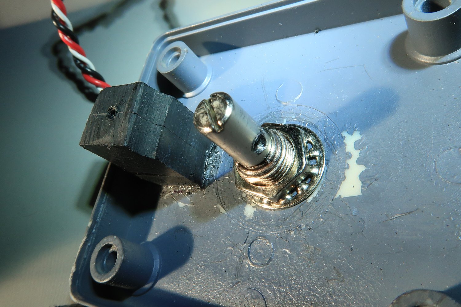
In the example discussed I I am not using a commercial string potentiometer.  Rather, a standard Bourne 3500-3501 rotary potentiometer has been adapted to use a string.

Requirements

You will need the following items:

  1. Bourne rotary potentiometer;

  2. Plastic housing box;

  3. 6 screws (to secure box lid and to fasten spool);

  4. One nut and washer (to secure potentiometer to box)

  5. A retractable spring-loaded spool and stainless steel or nylon string;

  6. A cylindrical piece if moulded ABS plastic (or wood); and,

  7. A small dog leash type clip or other fastening device (not pictured).

It’s best to use a CNC machine to fabricate the correctly shaped box, however, any box can be used.  Boxes can be purchased from electronic shops that are used as a housing for interface cards.  These are suitable.

It’s difficult to document exactly how the process is done, but by carefully studying the pictures, you should be able to replicate the process.

Fabrication

  1. Make a small hole in the side of the box for the string.  Ensure the hole enables the string to have some lateral movement.  You may need to attach some type of protection to the inside or outside of the hole so that the string doesn’t rub the plastic.  I have used a soft piece of plastic for this task (Figure 1).  Equally suitable is piece of cork (wine bottle)

  2. Drill a circular hole in the top of the box to enable the shaft from the potentiometer to be inserted.  Secure the shaft with a nut and washer (Figure 2).  The main body of the potentiometer will be outside the box.

  3. Glue a piece of solid ABS plastic (or wood) to the lid of the box.  Make a small drill hole that enables a screw to be attached.  This screw is used to help secure the retractable spool (Figure 2, 4 & 6).

  4. You must fabricate, from a piece of ABS plastic or similar, a cylindrical attachment that is glued to the retractable spring-loaded spool.  This piece if plastic must a hole drilled that is the same circumference as the shard of the potentiometer (Figure 3).

  5. The retractable spring-loaded spool is glued to the bottom of the box in direct line with the shaft of the potentiometer.  The shaft must align with the hole in the spool (Figure 1).

  6. Drill a small hole into the side of the shaft of the potentiometer and the retractable spool.  The hole should be large enough to enable a small screw to secure the retractable spring-loaded spool to the shaft.  This is done to stop the spool from freely spooling.  When it’s secured, the string when pulled in or out will turn the shaft of the potentiometer (Figure 2, 3 & 6).

  7. When everything is complete, the string should move the shaft of the potentiometer as it is pulled out of the retractable spring-loaded spool.  To secure the spring to the control device, a small clip can be used which is attached to the end of the string.  I have used a small dog leash style clip, but any clip will work.

Photographs

The fabrication as seen in the gallery photographs appear quite rough.  This is because the example photographed was a prototype.  If you are carefully, work methodically, and have an eye for detail, then there is no reason why the end product will not look semi-professional.


OEM Trip Reminder Indicator

Trip Reminder Indicator.  A small OEM part that is easily installed to any simulator

The trip reminder indicator (TRI) is a mechanical device installed to the right hand side of the yoke; it’s an airline option.  Basically, the device is three separate digits that can be rotated in any combination, from zero to nine.

The trip indicator is a memory device from which the crew historically used to record the flight number; the pilot uses his thumb to move the three digits to indicate the flight number.  However, over time flight numbers became longer than three digits and the use of the trip indicator, for it’s intended purpose, wanned

I use the trip indicator to dial in the Vref, as it’s often easier to quickly glance at the trip indicator to remind you of the Vref speed rather than look at the PFD or CDU.  Some dial in the Vref + wind speed.

Background

The trip indicator has a very long lineage beginning with the Boeing 707 aircraft.  The device was then ported to the 717, 727 and finally the 737 Classic and Next Generation airframes.

Installation and Backlighting

Because the OEM yoke already has the correctly shaped hole, installation of the trip indicator is straightforward.  If you are using an OEM yoke, you probably will need to carefully remove the blanking cover from the hole.

If a reproduction yoke is used, and the hole is not present, a circular hole will need to be cut from aluminium or plastic to enable the trip indicator to fit snugly into the yoke.  As the three dials are mechanical, there is no requirement to connect the device to an interface card.

Each of the digits on the indicator is backlit by a 5 volt incandescent aircraft bulb. 

The design of the trip indicator is ingenious, in that after the trip indicator has been removed from the yoke (two screws at the front of the yoke secure the indicator), a transparent acrylic slide can be unlocked to slide laterally from behind the three digits (see picture).  The acrylic slide accommodates three 5 volt bulbs, each in its own compartment.

To enable the backlighting to function requires two wires (positive & negative/common) to be connected to the appropriate connection on the rear of the trip indicator, and then to a 5 volt power supply.  The amperage draw from the three bulbs is minimal.  The wiring should be run through the yoke and down the control column so that it comes out at the bottom of the column.

In the aircraft, the backlighting for the trip indicator is connected to the panel light knob located on the center pedestal.  This enables the backlighting on the trip indicator to be turned on and off or dimmed. 

Final Call

The trip reminder indicator is but a small and unobtrusive item, however, it’s often the small things which add considerable immersion and enjoyment when using the simulator.  The trip indicator is also an OEM part that can be very easily installed to a reproduction yoke with minimal experience in fabrication and wiring.

Glossary

OEM - Original Equipment Manufacture.

Updating Firmware to Leo Bodnar BU0836A 12-Bit Joystick Controller and Button Box BBI 32/64 Cards

BUO0836A Joystick Controller card with wires from the string potentiometer (ailerons)

Nearly every flight simulator has hardware devices that need to be connected to the server computer, whether it be to control the buttons and levers on the throttle quadrant, flight controls, or any other add-on device.

Most enthusiasts can recall a time when they experienced a problem with a hardware device.  Perhaps the device couldn’t be calibrated, or when calibrated, the settings were not maintained.  Worst case scenario was the device didn’t function and wasn’t recognised by the computer.  Many of these potential problems can be minimised by ensuring that the firmware on the card is the latest version release.

In this article, I’ll discuss how to update the firmware the BU0836A 12-Bit Joystick Controller card.  The same process can be completed to also update the Button Box BBI-32 or 64 card.  Both cards are manufactured by Leo Bodnar Electronics.

Background

To connect a device to the computer, so that it can device can be recognised by Windows (and subsequently ProSim737 and flight simulator), requires an interface card of some description.  

Often, there isn’t much thought to addressing the firmware for the selected card.  The premise is if it works leave the card alone, and often this is the case, until you purchase replacement computer, upgrade your operating system, or install updates to the operating system.  Then, all of a sudden telltale symptoms emerge such as calibration issues, or in the worse case scenario, the computer fails to recognise the card.

Firmware

Any advanced interface card requires firmware.  The firmware at its simplest, is a basic set of instructions to enable the card to communicate with the computer’s operating system (think double helix, chromosomes and DNA). 

When a card is purchased, the firmware is usually up-to-date so that the card will function with the latest operating system.  However, with time many aspects relating to the computer change (hardware, drivers, operating system, etc).  However, rarely is the firmware on the card updated.  Some manufacturers don’t update the firmware; instead preferring to sell another card.  However, a reliable manufacturer will nearly always offer upgraded firmware, especially after a period of time in which there has been major evolutionary computer change (for example, WIN XP/7 to WIN10).

At the time of writing, the latest release for the BUO086 card was Version 1.26.

Screen grab of the User Interface from the HID flash tool

Upgrading Firmware (flashing)

The process of upgrading the firmware on either of the above-mentioned cards is  called ‘flashing’, and if done correctly is a straightforward process. 

Prior to a card being flashed, it’s necessary to download (from the Leo Bodnar website) the HID flash tool and the firmware versions for the card.

The flash tool is a standalone program and is used to read any Leo Bodnar card connected to the computer.  Once a card has been read by the software its firmware version number can be ascertained.

Important Point:

  • The latest version of the firmware for the BU0836A and BBI cards, and the HID flash tool, can be downloaded from the Leo Bodnar website (towards bottom of page).

Important Suggestions:

  • Do not install the HID flash tool to the computer used by flight simulator.  Rather install the program to another computer.  Disconnect the card requiring flashing from the flight simulator computer and reconnect this card to the second computer.

  • Only connect one card at a time to the computer.  Looking at multiple cards simultaneously can be confusing, and you may inadvertently ‘flash’ the wrong card.

  • Always try and use the shortest USB cable possible when flashing a card.

How To 'Flash'

In this example, we will discuss upgrading the firmware to a BU0836A Joystick Controller card.  The process is identical for the BBI 32/64 cards.  As this article is quite short, including diagrams is difficult.  Therefore, a copy of the instructions including screen grabs can be downloaded in the Documents Section.

1:  Download the HID flash tool and firmware version zip files from the Leo Bodnar website and unzip the files to your desktop.

2:  Connect the Leo Bodnar card to the computer and open the HID flash tool as Administrator (mouse right click/open).  The software will open at the User Interface that displays various information for the selected card.  Take note of the firmware version number.  If it’s the latest firmware, then there is no need to flash the card (unless you suspect a problem with the firmware).

3:  If more than one card is listed, select the correct card and click the 1. Bootloader tab.  This will place the card into flash mode.  The interface will display the word boot or bootloader.

4:  Click the 2. Browse file tab and navigate to where you downloaded the various firmware versions.  Select the correct firmware upgrade version.  The firmware is documented as .bin files.  I am told that all the bin files are identical, other than the number (more on this later). 

5:  Once the file is selected, click 3. Flash firmware.  The firmware will be flashed to the new version.

Important Points:

  • If it’s not possible to update the firmware (old or damaged card), then the User Interface will indicate the card is still in boot or bootloader mode.  In  this case, an updated card will need to be purchased.

Renaming Cards

if you use multiple cards.  Flashing can be a good way to change the name of the card to avoid confusion when looking at the card names in ProSim737.   Therefore, in Point 4 above, if you use .bin3, the card will be renamed to BU0836A_3 and if you choose .bin7, the card name will be BU0836_7 (and so forth).

Calibration Settings

It’s not uncommon for some calibration settings to be lost when a card is flashed.  Whether the settings are lost, depends upon how the card was used in the first place.  It's very likely the various axis will require re-calibration (ailerons, elevators, trim wheel and rudder), however, button settings should remain stable (because buttons are on/off and are connected to the terminals on the card).

Final Call

Computer hardware, operating system, and Windows updates can cause problems with various interface cards, especially if these cards are dated.  Fortunately, many manufacturers offer firmware that can update the card to enable it to operate flawlessly with a new up-to-date system.

Additional Information

Corruption of joy.cpl File Leading to Problems With Registration and Calibration in Windows 10

Every flight simulator uses input devices, and these devices must be initially registered and calibrated in the Windows Operating System, prior to advanced calibration in ProSim737 or FSUIPC.

Occasionally, the User Interface used to register and calibrate the devices fails or crashes.  One potential reason for the interface becoming unresponsive, can be caused by Windows 10 updates, that are automatically downloaded and installed to your computer.

While most updates are benign, some will tamper with settings that otherwise were thought to be ‘set in stone’.

In this article, I’ll discuss how the corruption of the joy.cpl file can lead to problems when attempting to register and calibrate joystick controllers.

Note that I use the word input device, game controller, joystick controller, and hardware device interchangeably.  Also be aware that the joy.cpl file is used in all late Windows operating systems (XP onwards).

Background

Flight simulator uses several hardware devices.  A basic list of the most commonly used is listed below:

  • Flight controls (aileron, elevators, steering tiller, rudder).

  • Yokes (buttons and elevator trim).

  • Throttle Quadrant (buttons, flaps lever, speedbrake lever, thrust levers, cut-off levers, parking brake).

Often, but not always, the items mentioned above are connected to the computer by a Leo Bodnar Joystick Controller or Button Box card (BU0836A and BBI-64 or similar).  These cards must be registered, and the connected potentiometers calibrated in Windows, prior to more advanced calibration in ProSim737 or FSUPIC.

Registration and calibration occurs in the Windows Joystick Calibration User Interface (Game Controller Interface).

It's often easier to think of calibrating controls as a two-stage process - Primary Registration and Calibration (in Windows) and Secondary Calibration (in Prosim737, flight simulator, or FSUPIC).

Joystick Calibration User Interface displaying opening menu and calibration menu

Registration and Calibration (Primary Calibration)

By way of an example, let’s assume a yoke is being connected to the computer via a Leo Bodnar BU0836A 12-Bit Joystick Controller card.   The movement of the ailerons and elevator (potentiometers) will need to be initially registered and calibrated in Windows.

To begin the registration process, open the Joystick Calibration User Interface and follow the prompts.  During the registration and calibration process, each of the end points for the movement of the potentiometer will be recorded, and an axis assigned to the aileron and elevator.  Initial calibration of each axis then occurs.  This information is saved into a file called joy.cpl.  

Important Point:

Calibration of any axis must involve moving the hardware device as far as possible (left, right, forward or backward).  This ensures that the full range of movement from the potentiometer is recorded during the registration process. 

A .cpl file is a .DLL file that stores information for other programs to access.  It’s part of the game controller applet and creates an entry in the Windows registry.  I don’t want to dwell any longer than necessary on the Windows infrastructure, as this information is readily available from the Internet.

Handy Shortcut:

  • There are several ways that the User Interface can be accessed: press 'WIN key and R' and then type either ‘joy’ or 'joy.cpl' into the search bar.   Another way is to type ‘joy’ or 'joy.cpl' directly into the Cortana search bar (Windows 10).

Corruption of joy.cpl File.

Initially you may not realise there’s a problem, until you discover it’s not possible to calibrate a device accurately in ProSim737 or in FSUPIC.  Or, if registering a new hardware device, the registration and calibration fails.  Corruption of the joy.cpl file will usually cause the Game Controller Interface to crash.

How the joy.cpl file becomes corrupted is unknown (by me).  I’ve read that Windows updates to sound drivers can sometimes cause an issue.  However, when I recently experienced a problem when attempting to register a new joystick controller card, removing and replacing the sound drivers didn’t rectify the problem.  

The Solution

Thankfully, the solution to this problem is relatively straightforward.  The joy.cpl must be deleted and replaced with a fresh copy.  

Important Points:

  • The corruption of the joy.cpl file is one of the most common reasons for registration and calibration problems, however, it may not be the only reason.

  • While Windows 10 updates can cause corruption of the joy.cpl file, there are other reasons that may cause this file to be corrupted.

Screen grab of the Sytem32 folder showing joy.cpl file

How to Repair the joy.cpl File

Rectifying the problem is a two-part process involving deleting the  joy.cpl file and replacing it with a fresh copy (non-corrupted) copy.

The joy.cpl is located in the Windows System32 folder (C:\Windows\System32).

Each computer system is slightly different, and depending on the file’s protection status, deleting the file may be difficult.  When attempting to delete this file, always log in as Administrator.  

If the file still can’t be deleted, a standalone unlocking program will be required.  As the name suggests, this program ‘unlocks’ the file (or any other file selected) so that it can be deleted.  There are several free unlocking programs available from the Internet.  I used a program called UnLocker.

Install UnLocker to the computer and follow the prompts after which the joy.cpl file should be able to be deleted.

Next, open the SysWOW64 folder (C:\Windows\SysWOW64).  Scroll downwards and find the  file joy.cpl file.  This is a copy of the file keep by Windows.  COPY this file and paste it into the System32 file.

After this has been done, registration and calibration of any hardware device should be possible.

Important Points:

  • It’s standard practice to always make a copy of any file prior to deletion (so you can rollback if necessary).

  • Always COPY the file from the SysWOW64 folder.  NEVER cut and paste.

  • When you replace the joy.cpl file, any settings previously held in registration may no longer exist.  If this occurs, registration and calibration will need to be done again for ALL hardware devices.

Backup Configuration Settings

The file that contains the configuration settings is the joy.cpl.

This file contains the information Windows needs to be able to load the settings obtained during Primary Calibration.  This file should be backed up.

Important Point:

  • If a problem develops at some point, it's an easy matter to replace the joy.cpl file with the backed up copy.  if the problem persists, then replacement of the file (from the SysWOW64 folder may be necessary).

Although Secondary Calibration has not been addressed in this article, it's recommended to backup these settings (included for completeness).  Recommended files to backup.

  • C:\Users\Your_Name\AppData\Roaming\Lockheed Martin\Prepar3D v4\Controls\Standard.xml, controls.xml and/or joysticks.xml

  • P3Dv4\modules\FSUIPC.ini

  • Prosim737\config.xml (located in ProSim737 main system folder)

  • C:\Windows\System32\joy.cpl.

Final Call

Not being able to register a hardware device in Windows can be frustrating and time consuming.  The registration and calibration information of any hardware device is recorded in the joy.cpl file.   If this file is corrupted, initial registration and calibration of hardware devices won’t be possible.  Prior to troubleshooting elsewhere, the first point of call should be to delete the corrupted file and replace it with another copy.

Using a Pololu JrK Card to Fine-tune the Calibration of Thrust Levers

OEM NG style thrust lever

The throttle quadrant for many enthusiasts is the ‘holy grail’ of the simulator, and many individuals strive to ensure that the throttle operates as close as possible to its real world counterpart. 

The automated systems in the 737 aircraft drive the movement of the thrust levers in a coordinated manner, and it’s the accuracy, speed, and  synchronised movement that enthusiasts try to replicate.

Historical Context

Individuals often use Leo Bodnar Joystick cards, PoKeys, Arduino, and Phidget Advanced Servo cards to interface the throttle quadrant (and other hardware) with some using SIOC (a programming language) to connect propriety throttle quadrants.  Calibration, more often than not, was done via FSUIPC, or in a rudimentary way through ProSim737.

Although the throttle quadrant functioned, the position of the levers didn’t match the correct position for the commanded thrust (%N1), and the thrust levers would often be offset against each other and not move in a synchronised manner.  These shortcomings lead to the throttle being used only in ‘manual mode’, as the feedback from the software to the throttle didn’t generate consistent and reliable results. 

Two innovations have changed this – the introduction of Direct Calibration in ProSim-AR, and the development of the Pololu Jrk Interface Card. 

In this article, I’ll explain how to the calibrate the thrust levers using Direct Calibration in ProSim737.  I’ll also show you how to initially calibrate, and then fine-tune the Pololu Jrk card, to enable seamless integration with ProSim737.  Finally, I’ll discuss some advantages that using a Pololu card brings.

Important Point:

  • The calibration settings displayed in the various figures (Figures 1-5) are specific to one simulator.  The Pololu card settings in your simulator will be similar, however, some settings will be different because of subtle differences in the hardware being used.

ProSim-AR - Direct Calibration

ProSim-AR enables direct calibration of the various flight controls and surfaces directly within ProSim737.  This is in-line with their philosophy of trying to keep everything in-house (homogeneous) within ProSim-AR.  This not only enables ProSim-AR to maintain control of how the calibration process occurs, but it also aids in troubleshooting should a problem occur. 

Direct Calibration is a step forward in keeping ‘everything under one roof’ as opposed to using FSUIPC or another programming language to connect aircraft-related assignments.  At the time of writing, it is possible to use direct calibration for the: throttle levers, flaps lever, tiller, speedbrake, aileron, elevator, and rudder.

On a side note, Direct Calibration is one of the strengths of ProSim-AR, in addition to built-in native support (via their SDK and generic driver) for various interface cards (which includes the Pololu card).

Pololu JrK Interface card

Pololu Jrk Interface Card

The Pololu Jrk Interface card is a powerful and highly configurable 12v12 brushed DC motor controller, that provides a stable and robust solution to interface the automated movement of the thrust levers in a simulator environment.  Not only are the cards small, but they have been trialled extensively in robotic assignments; NASA uses an upmarket version of the Pololu JrK card to control aspects of the Mars Lander.

The card comes packed with a number of advanced features that enable you to tweak the interaction of the card with ProSim737 which, when combined with a quality 12 volt DC motor and string potentiometer will guarantee higher accuracy and better performance than when other calibration methods are used. 

Using ProSim737 and a Pololu Jrk Card to Calibrate Thrusts Levers 1 and 2

The engineering required to enable movement of the thrust levers is comparatively simple.

Each thrust lever is connected with a string potentiometer that in turn connects with a Pololu JrK card.  The Pololu card then connects directly to the computer by a USB connection.  This creates a closed loop system in which the Pololu card reads the movement of the potentiometers and sends this information to ProSim737 and then to flight simulator.

Obviously, two Pololu cards and two potentiometers are needed; one for each thrust lever, and the calibration of each thrust lever must be carefully done to enable both levers to move together in unison.  Additionally, two 12 volt DC motors are needed to provide the power to move the thrust levers.

To connect and calibrate a Pololu JrK card requires three steps (in sequential order):

(i)      Download and install the Pololu software;

(ii)     Turn on Pololu support in ProSim737 (Configuration/Drivers);

(iii)    Configure the initial settings in the Pololu Configuration Utility (PCU);

(iv)    Calibrate the thrust levers in ProSim737 (Configuration/Levers); and

(v)     Fine-tune the calibration in the Pololu JrK card using the Pololu Configuration Utility (PCU).

Once Pololu support has been selected in ProSim737, the Pololu card will be read automatically by ProSim-AR, and the calibrated settings sent to flight simulator. 

Important Point:

  • Initial configuration in the Pololu card (iii) must be done prior to calibrating the thrust levers in ProSim737 (iv).

Subtle Differences (Hardware)

Every throttle quadrant is different as we use different hardware, potentiometers, and DC motors.  It’s important to understand that, subtle differences in the hardware used in the throttle quadrant, will affect which settings are used to configure the Pololu card.

The following may have a direct effect on the accuracy, speed, synchronisation, and movement of the thrust levers.

(i)     Type of 12 Volt DC motor used;

(ii)    Variable output between DC motors;

(iii)   Type of potentiometer and the manufacturing variance (+/-) between units;

(iv)   The friction generated by each of the thrust levers; and,

(v)    The manufacturing variance (+/-)between each of the Pololu cards.

The type of potentiometer used will make a difference to how accurately the Pololu card can read the movement of the thrust levers.  If an inexpensive linear potentiometer is used, then the accuracy will continually degrade as the carbon trail on the potentiometer is slowly destroyed.  This will lead to frequent recalibration and fine-tuning of the settings. Using a string potentiometer will resolve this issue as contamination leading to loss in calibration is minimal. Use of a Hall sensor will deliver an even greater degree of accuracy (as these sensors are extremely accurate), although it’s debatable to exactly how much more accuracy will be achieved in the movement of the thrust levers, and whether this will be noticed. 

High-end string potentiometers and Hall sensors are often used in the medical industry where the tiniest input movement needs to be accurately measured.  In comparison, the movement of the thrust levers (input) is quite rough.

Performance can also be affected by the type of 12 volt DC Motor used.  If the motor has an amperage either too high or low, or the incorrect gear ratio, the thrust levers may be over or under powered, and no matter what finesse in calibration, the results will be less than optimal. If a low end motor or a hobbyist servo is used, the resolution of the motor steps will not be good enough to deliver a smooth transition when the thrust levers move; the levers will stagger as %N1 changes.
Also, depending on the type of throttle you’re using, the friction caused by the thrust levers moving will also be different; some levers move relatively easily while others require additional torque from the DC motor to move.

Interestingly, if you’re using an OEM throttle, there may also be differences between throttle unit builds, as each throttle quadrant is manufactured to be within a range of specific tolerances (manufacturing variance).  For example, the friction needed to be overcome to move the thrust levers is often different between throttle quadrants, and even respective levers on the same quadrant.

RAW data from thrust lever 1 during automated flight.  The upward and downward spikes signify major departure from acceptable operation.  The red line demonstrates how the spikes can be flattened when a Pololu card is used

Calibration of the thrust levers in ProSim737 without using a Pololu card does a reasonable job, however, the output is often quite rough – think of a graph with lots of upward and downward spikes. 

For consistent smooth operation the spikes shown in Figure 6 must be smoothed down.  A Pololu card enables fine-tuning of this output to achieve a consistent and repeatable output

Installing the Pololu JrK Card Software and Initial Configuration

Although ProSim-AR will automatically read the Pololu card, you’ll still need to install the Pololu software to enable access to the Pololu Configuration Utility (PCU).

Two Pololu JrK cards installed to Throttle Interface Module (TIM).  The compact size of the cards is readily apparent.  These cards deliver a big ‘punch’ for such a small size

After downloading the software from Pololu, open the ZIP archive and run ‘Setup.exe’. If the installer fails, you may have to extract all the files to a temporary directory, right click ‘Setup.exe’, and select ‘Run As Administrator’.

The installer will guide you through the steps required to install the Pololu Jrk Configuration Utility, the JrK Command-line Utility (JrkCmd), and the JrK drivers on your computer.

Once the software has been installed, there should be an entry for the JrK in the ‘Pololu USB Devices’ category of the Device Manager. This represents the card’s native USB interface, and it is used by the configuration software. 

Recommendation:

  • Create a shortcut to the Pololu Configuration Utility (PCU) and save this shortcut to your desktop or menu system.  This will enable quicker and easier access to the utility.

Limitation

For brevity and simplicity, I haven’t discussed every configuration setting in the PCU.  Instead, I’ve included several screen captures (Figures 1-5) that show the various configuration settings for reference.  These settings should provide a benchmark to enable you to configure the card. 

Notwithstanding this, I have enlarged on the two most important settings in the PCU that have a direct influence on the accuracy, and synchronised movement of the thrust levers. 

Confirming the Pololu Card Connection

After the initial configuration settings in the Pololu card have been configured, it’s a good idea to test the card’s functionality to confirm connection with ProSim737.  This is done by opening the Pololu Configuration Utility (PCU) and setting a manual target speed (Figure 1).  To engage the target speed, select ‘Apply’

Pressing ‘Apply’ will command the card to determine the position of the thrust lever as indicated by the potentiometer.  If the thrust lever is not at the same position on the throttle arc as indicated by the settings in the PCU (and it probably won’t be), the thrust lever will move to the commanded position.  If this movement occurs, it’s a good sign that everything is functioning correctly.

Calibrating Thrust Levers in ProSim737

Assuming everything is working, the next step is to calibrate the thrust levers in ProSim737.

Calibrating the movement of the thrust levers is comparatively straightforward.  Each thrust lever must be calibrated independently of each other, otherwise both levers will not move in unison when the automation (aircraft autopilot) is selected.

(i)     Enable Pololu support in Configuration/Drivers tab in the ProSim737 User Interface;

(ii)    Open the Configuration/Levers tab and assign for each throttle lever the Pololu input and output;

(iii)   Select the appropriate Pololu card for the analogue input and select ‘Feedback input’(1);

(iv)   Select the appropriate Pololu card for server output and then select ‘Motor output’(1); and,

(v)    Move the virtual sliding tab with the mouse (you should see the respective thrust lever moving).

(1) Located in adjacent drop down box.

To calibrate each thrust lever the virtual sliding bar is moved with the mouse device.  To register the position the ‘Min’ and ‘Max’ is selected. 
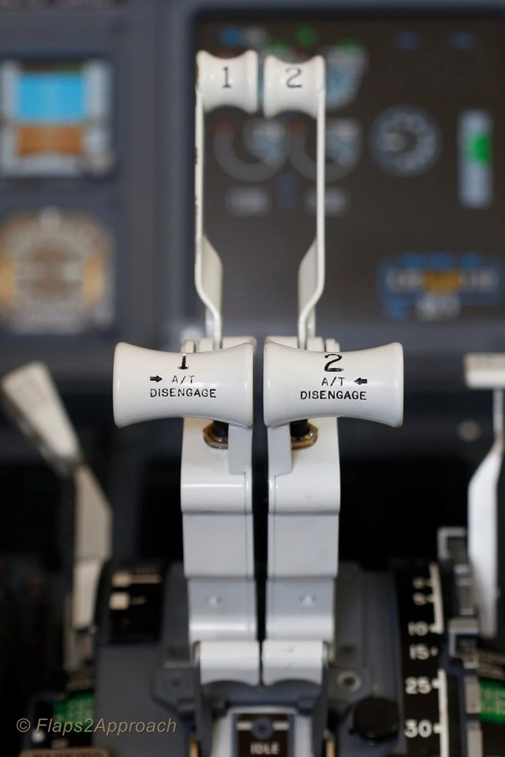
Slide the bar until the physical thrust lever rests in the idle position (the physical thrust lever should move as you slide the bar).  When the thrust lever is in the idle position select ‘Set Min’.  Next, move the virtual sliding bar until the position of the physical throttle lever rests in the fully forward position.  When it does select ‘Set Max’

For calibration to occur, the minimum and maximum positions must be registered.  This process must be completed for both thrust levers.

Important Points:

  • On some set-ups the ProSim737 software reads the throttle movements backwards.  In other words the position of the thrust lever will move in the wrong direction.  If this occurs, reverse the order - press ‘Set Max’ instead of ‘Set Min’ and ‘Set Min’ instead of ‘Set Max’.

  • Calibration occurs when the virtual sliding bar is moved with the mouse device.  Calibration is NOT done by physically moving the thrust levers.

  • To improve accuracy, select ‘Min’ and ‘Max’ only when the physical thrust lever has reached the end of its movement cycle.  This task may need to be done a few times to ensure the most accurate position is registered by the calibration process.

  • Ensure the option ‘closed loop autothrottle’ is NOT selected within the ProSim737 MCP software (right click the virtual MCP to open the MCP Config menu.

  • It’s recommended to use string potentiometers or Hall sensors to register the incremental movements of the thrust levers.  These will provide a greater degree of accuracy.

  • Always calibrate the thrust levers in ProSim737 prior to fine-tuning the Motor and PID in the PCU Interface.

  • It’s at the discretion of the user to calibrate and fine-tune the Pololu card to a level of accuracy they believe is a reasonable compromise between the position of the thrust levers on the throttle arc, and the speed at which the thrust levers move.

Fine-tuning Using The Pololu Configuration Utility (PCU) Tabs

To fine-tune the outputs from the throttle quadrant, the PCU must be opened.  The two tabs that are used to determine the accuracy, position, speed, and synchronisation of the thrust levers are the Motor and PID tabs.

The Motor Tab in the PCU (Figure 4) can be used to alter the current (amperage) and the duty cycle.  Both settings affect the output of the motor (which in turn alters the speed that the thrust levers move).

If the motor has an amperage either too high or low, then the speed that the thrust levers move at, may either be too slow or too fast.  Furthermore, DC motors often exhibit manufacturing variances (+/-)and it’s common to have 2 identical motors with slightly differing output.

If the output is not equalised between the two motors, the position of the thrust levers will be staggered and synchronisation between each of the levers won’t be possible.  Likewise, a different power output may be required to overcome the internal friction of the thrust lever, to enable movement of the lever to occur, . 

Tweaking the motor duty cycle will help eliminate these differences enabling synchronisation of the thrust levers.

The PID Tab in the PCU (Figure 3), an acronym for proportional coefficient, enables in-depth fine- tuning to be applied to the already completed calibration done in ProSim737.

Depending on the power (torque) of the DC motor and the hardware used in the throttle quadrant, the thrust levers may jitter (backward and forward movement when a constant %N1 is set).  To eliminate jitter, the PID is fine-tuned until a happy medium is discovered.

Consistency and Reliability

For the most part, Pololu Jrk cards are manufactured to a high quality and are very reliable; you shouldn’t experience a problem with a card.  Even so, there may be manufacturing variance (+/-)between respective cards.  However, because of the nature of the card, any subtle differences in output can easily be controlled through fine-tuning. 

The above said, the calibration of the thrust levers includes many variables that are interrelated, and to achieve consistent results, the components that provide information to the card, in particular the potentiometers and DC motors, must be of the highest quality.

Important Point:

  • If something doesn’t work as expected, try again using different variables.

Advantages Using a Pololu JrK Card

The benefits of using Pololu Jrk cards cannot be underestimated. 

(i)    Direct support (reading of card) by ProSim-AR;

(ii)   Small size enabling mounting almost anywhere; and,

(iii)  Fine-tuning and increased accuracy through use of the PSU User Interface.

Will I Notice A Difference Using a Pololu JrK Card

The question frequently asked is: ‘will I see a difference if a Pololu card is used’  The answer is not straightforward, as there are several interrelated variables (already discussed).  If the calibration is done carefully in ProSim737 and the variables tweaked in the Pololu PCU, there is no reason why there shouldn’t be a marked improvement.

Addendum

There has been considerable confusion concerning using the Pololu JrK card with ProSim737. Specifically, whether the potentiometers can be connected directly to the Pololu card, whether dual potentiometers are required, and whether a joystick card, such as Leo Bodnar BU0863 A/X joystick card is required to calibrate the thrust levers.

The ProSim737 software has the ability to read the Pololu card directly. Therefore, the potentiometers can be connected directly to the Pololu card. Because direct connection is possible, a duel potentiometer is not required. The calibration of the thrust levers can be done directly in ProSim737. A joystick card is not needed.

This said, the throttle quadrant in my simulator uses dual potentiometers that connect directly to the Pololu JrK card (to provide feedback) and to a Leo Bodnar BU0836A card (for calibration). The later also being used to register and calibrate the throttle buttons, flaps and speedbrake lever.

Advantage of this methodology, although it does appear slightly convoluted, is three-fold:

  1. The calibration of the thrust levers and feedback can be separated. This can aid in troubleshooting if a problem occurs;

  2. The calibration of the thrust levers can be done outside of ProSim737 using FSUIPC, flight simulator or some other software (if required);

  3. The thrust levers can be used in manual mode without feedback connected. This is because the calibration has been done using a joystick card; and,

  4. By using duel potentiometers and a joystick card you have the option of using other avionics software. In other words you are restricting yourself to only using ProSim737 because of a specific hardware configuration.

Final Call

Evolution is rarely static.

Direct calibration has enabled greater accuracy in calibrating the various control surfaces within ProSim737 and, in concert with using an advanced card such as the Pololu JrK card, has been a evolutionary step forward.  This has lead to greater accuracy in the position of the thrust levers on the throttle arc, and almost perfect synchronisation, when automation is selected.

Further Information

This is but a short introduction to calibrating the throttle quadrant (thrust levers) directly within ProSim737 using the Pololu Jrk interface card.  For further information concerning the Pololu Jrk card and it’s use with ProSim-TS navigate to the ProSim737 forum and search Pololu. The Pololu website is also worth reading at Pololu.

Acronyms and Glossary

  • Manufacturing Variance (+/-) – This is where identical items, although appearing exactly the same are very slightly different.  Usually the tolerance is so small that it’s indiscernible.  However, manufacturing variance in electronics often is the reason why some parts function and some fail soon after first use.  An acceptable tolerance will be defined at the point of manufacture.  Usually, if an item requires a higher (tighter) tolerance this leads to a higher manufacturing and purchase price.  Often, but not always, there is a direct relationship between the price paid for an item and the reliability and longevity of that item.

  • MCP – Mode Control Panel

  • PCU – Pololu Configuration Utility

  • Throttle Arc – The curved piece of aluminium that the thrust levers move within.

Figures 1–5 display the settings for each of the tabs in the Pololu Jrk Configuration Utility  (PCU).  Note that these settings are generic to all throttles, however, the variables will differ slightly depending upon hardware used.