2012 - 2013: Seasons Greetings, Thank You & 2013 Plans

First, "Merry Christmas and Seasons Greetings"

Flaps2Approach has been live since the 737 project commenced in September 2010.  On average, each week the site receives over 10,500 individual hits and 32,000 page views from nearly every developed country on the planet.  I hope the site has provided YOU with information, ideas, interesting reading, and enthusiasm to either begin or continue your own 737 project.

I enjoy documenting the project; I find it helps clear my thoughts!  I hope I have not made too many spelling or grammatical mistakes in the posts.

Thank You

A project of this magnitude is not a one person job; many people have provided advice, assistance and most importantly their personal time in helping me achieve what you see today.  I'd like to thank each person for their help; a number of you (you know who you are...) have been exceptionally patient with me as I learn new skills to add to my quiver.

2012 - Almost Gone!

The new year will be upon us shortly and although much of the construction of the flight simulator has occurred during the past year, 2013 will see some major enhancements as the simulator evolves further toward a fully workable simulator. 

Milestones accomplished during this year have been the conversion of the 737-300 throttle quadrant, two converted OEM 737 ACP units, a replacement of the former platform with a more sturdy, functional platform, and installation of dual rudder pedals and OEM control columns.

What's Planned - 2013

On the near horizon we will see the implementation of full automation of the Boeing 737 throttle quadrant and complete functionality of the speed brake system which will replicate exactly the operational status of the real aircraft.  It's also hoped that OEM parts will become available to develop the forward and aft overhead.  This is in addition to replacing some of the reproduction gauges on the MIP with converted OEM components, such as the brake hydraulic and flaps indicator gauges.

Later in the year, the method in which the overhead is to be mounted will be decided (roll frame or shell) and the external visuals, which to date have not been adequately addressed, will be looked at in detail. 

No doubt, as 2013 progresses there will be a host of other small improvements and most importantly, the opportunity to spend some time behind the yoke actually flying - which I have sourly missed for the past 15 months or so....

OEM Boeing 737 Control Columns - A Closer Look

OEM Captain-side 737-500 series control column.  Previously used by Croatian Airlines

The two control columns have been refurbished and installed into the simulator.  The control columns previously were used in a 737-500 airframe operated by Croatian Airlines. 

I was fortunate to have been able to secure these columns, and although there is some wear on the yokes, the buttons, electric trim switches, chart holders, and trip indicators are operational and in good condition.  Furthermore, a working stick shaker is attached to the captain-side control column.

In this article, I use the words control columns and yoke interchangeably.

Mechanical Set Up

To allow the two columns to be fitted to the 5 inch high platform, the lower cogs have been removed and replaced with bearings.  The bearings support a high strength stainless shaft that connects to a rotating disc beneath each of the columns; movement is synchronised between control columns.

Physical movement of the control column is registered by high-end string potentiometers and any movement converted to an electrical signal that can be read by the interface card.  The interface card used is a Leo Bodnar 836X joystick controller.

The interface card, electrical wiring and potentiometers are installed on a piece of plastic board mounted to a dust proof box and attached to the underside of the platform.  Access to the box is via the front of the platform.

Push and Pull Pressures

In the real Boeing 737 aircraft the control columns are hydraulically driven, and a fail-safe cable mechanism provides redundancy should the hydraulics fail.  The 737 is rather unique in that, although hydraulics control movement of the control column, the pressures needed to move the columns (by hand) are quite stiff.  Therefore, hand flying a 737 can be quite tiring; you must use a little muscle to move and maintain the position of the controls.

The specifications for the real aircraft state that the control column has a 37 pounds push/pull value +- 4 pounds, while the roll pressures are 12 pounds +- 3 pounds.  These pressures can differ from aircraft to aircraft, but fall within the published specifications. To replicate the push, pull and roll forces as accurately as possible, four heavy duty springs have been fitted to the column mechanism. 

Heavy duty pre-tensioned springs provide accurate static control loading

The control column pressure can be adjusted by either replacing the springs with higher or lesser tension springs, or by disengaging the outer springs. 

A pressure test determined that push/pull pressure is 20 pounds and roll pressure 15 pounds.  The push/pull pressure is on the low side, however, will be left as is for the time being.  Springs have been used rather than hydraulic rams due to the simplicity of a spring and ease of replacement.

Although the use of springs is rudimentary, it's acts as an interim measure until control force feedback is installed.  When this is done, the force required to move the control column will alter based on aircraft's speed, flap setting, landing gear position and other environmental variables.

The video at the bottom of this article demonstrates the linkage mechanism and springs in motion.

Configuration - Movement and Buttons

Configuration of the control columns is straightforward. Although there are two control columns, each column is linked to the other.  Therefore, only one interface card is required.  The buttons on the yoke, and the electric trim switch are connected to the outputs on the interface card.

Initial registration of the movement of the yoke and buttons is established in the Windows joystick calibration software.  Further calibration is either done directly in the flight simulation program, FSUIPC, or in ProSim737.  Although it is possible to assign buttons directly via the flight simulator set-up menu, the preferred method is to use FSUIPC or ProSim737.

Backlighting (Trip Indicators)

The actual yoke doesn't have backlighting; any illumination of the yoke is achieved by focusing the map light which is attached to the overhead panel.  However, the numbers on the trip indicators do have backlighting (to illuminate the numbers). 

Trip indicators are an airline specific option and do not come as standard issue.  Pilots use the trip indicator to 'scribe' the flight number of the flight, or to document the Vref speed.  Some crews never use the indicators.  I use the trip indicator as a ready memory pad to document the landing Vref speed (Vref+5).  The backlighting for trip the indicators is powered by 5 Volts.

oem chart holder and cheat sheet

Chart Holders

The chart holder is used to secure the approach plate (paper chart) in an area that it can easily be read during flight operations.  The chart holders have a folding mechanism beneath the plate that allows the holder to be either pushed flush to the yoke, or positioned at a user-selected angle. 

Another function of the chart holder is to provide a ready memory jogger for specific flight modes (checklist).  The adhesive transfer on which this information is printed is specific to each aircraft type and /or airline.  illumination of the chart plate, like the yoke, is achieved using the map light.

OEM Verses Reproduction

Several companies manufacture reproduction control columns: Precision Flight Controls (PFC), CH Products, Revolution-Sim and Ace Engineering to name a few.  Over the years I have used products from ACE, CH Products and PFC.  Without transgressing into a 'tit for tat' argument, you get what you pay for.  

A CH yoke retailing at $100.00 cannot be compared with an ACE yoke retailing around $1300.00, however, both products have been manufactured to cater towards differing segments of the market.  This said, the difference between ACE and PFC is marginal.  I cannot comment on Revolution-Sim having not used their products. 

So what is the different between a high-end reproduction yoke and a OEM yoke and column?

The main difference is the feel and finesse of the genuine item.  Boeing has spent a lot of money (more than PFC, ACE or Revolution-Sim combined) in the development and engineering of the control column, and this is very difficult to replicate in a reproduction.

The OEM yoke and column is engineered to provide faithful service for many years.  It's also built to suffer use and abuse from real-world pilots, and I am certain anything a virtual pilot can throw at it, will not cause any damage.  The buttons and electric trim switches are solid, feel good to manipulate and are very reliable.

Yoke Performance

The yoke moves left and right across its range of motion with a smooth and silky feel without staggering, binding or rough patches.  Likewise, the columns move forward and aft very smoothly.

The electric trim switches are far more responsive than the reproduction switches I have used.  A slight application of pressure to the switch engages the electric trim.  The electric trim switches response is a akin to a hair trigger on a firearm - it only needs a light touch to engage. 

The control column is very responsive, and if calibration has been done correctly, very accurate.  If the yoke is turned 15 degrees to the left, the measurement on the aileron tape is exactly 15 degrees.

Synchronization

I was concerned that synchronisation between the two control columns would not be perfect, however, my concern was short-lived.  The use of high-end bearings at the end of the control linkages removes any chance of slop (loose movement) between the two control columns. 

Yoke Switches

  • OEM 737 yokes have several switches and buttons.

  • Momentary press push button - auto pilot deselect.

  • Momentary rocker switch - electric trim up/down. This switch is interesting as it incorporates redundancy.

  • Momentary rocker - push to open channel (push to talk PTT).

  • Rocker switch - Intercom.

  • Trip Indicator - used as memory aid for flight number.

oem 737 flight controls in simulator

Appearance of Yoke - Used Look

If you carefully study the pictures of the yokes, you will observe that the yokes are not pristine condition, but show solid use (and probably abuse when it was striped from the aircraft).

The baked-plastic covering of the yoke shows scratches and some of the metal has been rubbed clean of paint.  Some enthusiasts dislike this look and prefer a brand new 'out of the showroom' appearance.  If this is you, then I suggest an OEM yoke may not be for you, unless you wish to completely overhaul the yoke and pay the large amount of money required to re-bake the plastic coating.

I like the 'used' look and feel it adds to the simulator.  I have been in many cockpits, and very rarely do you find a flightdeck in brand new condition, other than in the first few months of service.  More often than not, gauges, yokes and panels are scratched, dented and stained from many hours of sustained use from individuals that are more interested in flying, and going home after the flight, than maintaining the desk!

Below is a short video showing the under floor mechanism, springs and linkage rods.  If you listen carefully you will hear the springs creaking.  This is not an issue when the simulator is running as any noise is cancelled out by the noise of the engines and flight deck ambient noise (electrics, 400 hertz noise and wind).


Glossary

Control Wheel - Yoke.

FSUIPC - Flight Simulator Universal Inter-Process Communication (interface software that provides a bridge between flight simulator and outside programs).

OEM - Original Equipment Manufacturer (aka real aircraft part).

  • Updated 20 June 2020.

Digital Chronograph Running ProSim737 Software

The Main Instrument Panel (MIP), unless a special order is made, usually will not include a chronograph.  Depending upon the MIP manufacturer, the MIP may have a cut out for the chronograph, a facsimile of a chronograph or just a bezel. 

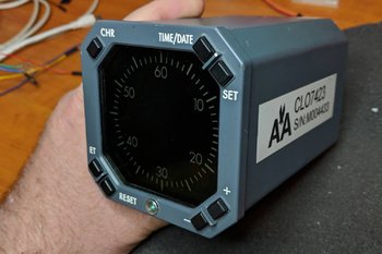
LEFT:   OEM chronograph used by America Airlines.  Nothing beats an OEM item, however, in this case conversion is difficult and a reproduction more cost effective.  Image courtesy of Micks737.

The Next Generation aircraft mostly use digital chronographs. The classic series airframes usually use (unless retrofitted) mechanical chronographs.

After Market Chronograph

There are several after-market chronographs that can be purchased.  SISMO Solicones produce a mechanical type that replicates the real world counterpart quite well, despite the awful orange-coloured backlighting.  Flight Illusion produces a quality instrument as does Flight Deck Solutions (FDS).  FDS replicate the digital chronograph. 

Chronographs are manufactured by several companies and not every chronograph looks identical, although their functionality is.  There are a few different styles available to an airline.  The main difference is in the number and shape of the buttons; round or rectangular.

No matter which type you decide, be prepared to shell out 250 plus Euro per chronograph; for an item rarely used it's quite a financial outlay.

Converting OEM Chronograph

Converting an OEM B737 mechanical chronometer is a valid option and the process of conversion is relatively straightforward.   However, finding a mechanical chronograph in operational order is difficult, as airlines frequently keep chronographs in service for as long as possible.  Converting a digital chronograph is also an option, however, the initial price of the item and then conversion make this an expensive exercise.  Add to this the fact that converting the chronograph, due to its internal digital electronics is very difficult (even if you use ARINC 429 protocol).

Another option is to use the virtual chronometer (Sim Avionics and ProSim737) and fabricate a reproduction bezel that overlays a small LCD screen.

ProSim737 Virtual Chronograph

Screen capture of ProSim737 chronograph.  ProSim737 have a Chronograph that can be used for the Captain and First Officer side of the MIP.  There are seevral version of the display that can be used

ProSim737 as part of their avionics suite have available a virtual chronometer.

The display used by ProSim737 is very crisp, the size is accurate (1:1 ratio), and the software allows complete functionality of the chronograph. 

To use the virtual version a small computer screen is needed on which is displayed the virtual chronograph.

Chronograph

A friend of mine indicated that he wanted to make a chronograph for the simulator and use the virtual ProSim737 display.  He also wanted to incorporate the four setting buttons and have them fully functional. 

The components needed to complete the project are:

  • A small TFT LCD screen (purchased from e-bay);

  • A standard Pokey interface card;

  • Several LEDS; and,

  • Four small tactile switches and electrical wire. 

I currently use an Main Instrument Panel (MIP) fabricated by Flight deck Solutions (FDS).  Therefore, the chronograph bezel used in this project was that supplied by FDS.

The screen used was 5.0" TFT LCD Module with a Dual AV / VGA Board 800x480 with a 40 Pin LED Backlight. 

The screen was small enough that it just covered the circular hole of the cut out in the FDS MIP.  The TFT LCD screen uses a standard VGA connector cable, 12 Volt power supply and a USB cable to connect the POKEY card to the computer.  

The holes in the box provide ventilation for the Pokeys card.  The only portion of the box that is visible from the front of the MIP is the bezel and four buttons

Two-part Fabrication

FDS supply with their MIP a bezel with four solid plastic but non-functional buttons.  The bezel does not support direct backlighting, nor does it have enough space for tactile switches or wiring. 

Therefore, the FDS bezel must be modified to accommodate the wiring for the switches and LED illuminated backlighting. The easiest way to approach this modification is to use a Dremel rotary tool with a 9902 Tungsten Carbide Cutter.

Place the bezel on a hard surface using a towel to avoid scratching and damaging the bezel.  Then, with 'surgical' accuracy and steady hands carve out several channels (groves) at the rear of the bezel.  The channels enable placement of the miniature tactile switches, small LEDS and wiring. 

Space is at a premium, and to gain addition real estate, the LEDS were shaved to remove excess material.  This enabled the LEDS to fit into the excavated groove on the bezel.  Be very careful when using the carbide cutter to not punch out onto the other side of the bezel. 

The four solid plastic front buttons on the bezel are carefully removed and small tactile switches attached (glued) to the rear of each of the buttons.   26/28 AWG wire is used to connect the tactile switches (using common ground leads) to a PoKeys interface card. 

The box is not seen as it's attached to the rear of the MIP.  My friend's humour - several warning signs suggesting that I not tamper with his creation :)

Box Fabrication

A small box needs to be fabricated to house the Pokey card.  The size of the box is controlled by the size of interface card used and the length and width of the LCD screen. 

A box is not required, however, it's a good idea as it illuminates the need to seal the LCD screen to illuminate dust ingress between the screen and overlying glass in the bezel. 

The material used to fabricate the box is plastic signage card (corflute); real estate agencies often use this type of sign.  The main advantage of this material is that it’s not difficult to find, is light in weight, and it's easy to cut, bend, and glue together with a glue gun.    

After the Pokey card is installed to the inside of the box, and the LCD screen attached to the front edge, the bezel needs to be secured to the front of the LCD screen.  The best method to attach the screen and bezel is to use either glue or tape. 

A hole will need to be made in the rear of the box to enable the fitment of the USB and VGA connectors.    Small holes punched into the side of the container ensure the LCD screen and PoKeys card do not overheat.  If you're concerned about heat buildup, a small computer style fan can easily be added to the box, but this does add complexity and is not necessary.  To conform to standard colours, the box is painted in Boeing grey.

LED Backlighting

Careful examination of the backlighting will show that the light coverage is not quite 100%.  There are two reasons as for this.

(i)    There is limited space behind the bezel to accommodate the wiring and the LEDS; and,

(ii)   The material that FDS has used to construct the bezel is opaque.  The only way to alleviate this is to replace the stock bezel with another made from a transparent material.

Important Point:

  • If you want to try and replicate the digital OEM chronograph as closely as possible, that the OEM version does not use backlighting.  Illumination of the front of the chronograph is by the MIP lighting.

Potential Problem

Depending on the MIP being used, there maybe space constraints that do not allow a 5 inch screen to be easily positioned.   If you're forced to use a smaller screen, the outcome will be that you may see the screen edges within the bezel.  For the most part this is not an issue, if you ensure the desktop display is set to black.  Remember, you are looking at the chronograph from a set distance (from the pilot seat) and not close up.

ProSim737 Virtual Chronograph (position and set-up)

This task is straightforward and follows the same method used to install and position the PFD, ND and EICAS displays.  

Open ProSim737’s avionics suite and select the virtual chronograph from the static gauges:  resize and position the display to ensure the chronograph conforms to the size of the bezel.  To configure the buttons on the bezel, so that ProSim737 recognizes them with the correct function, open the ProSim737 configuration screen and configure the appropriate buttons from the switches menu (config/switches).

The four functions the buttons are responsible for are:

(i)    Chronograph start;

(ii)    Set time and date;

(iii)   Expired Time (ET) and Reset; and,

(iv)   +- selection

NOTE:  The above functions differ slightly between the panel and the virtual chronograph in use.

Chronograph Operation and Additional Configuration

Captain-side CLOCK start button.  Connection between the clock button and the CHR button is made in the assignments page in ProSim737 (FDS MIP)

The chronograph can be initiated (started) by either depressing the CHR button on the top left of the clock, or by depressing the CLOCK button located on the glarewing of the MIP. 

Configuration

Connecting the CLOCK button to the chronograph start (CHR) function is straightforward.

Connect the two wires from the Captain-side clock button to the appropriate interface card and configure in the switches tab of ProSim737 (config/switches/CAPT CHR).

The same should be done with the First Officer side CLOCK button and chronograph, however, ensure you select the FO CHR function in switches to be done for the First Officer side chronometer if fitted.

If configured correctly, one press of the CLOCK button will start the chronograph, a second press will stop the chronograph, and a third press will reset the chronometer to zero.

After Market Chronograph

For those wanting to use an after market chronograph, SimWorld in Poland and Flight deck Solutions (FDS) in Canada produce high quality chronographs that can be dropped into the MIP with minimal required fabrication.

Video

A short video (filmed at night) showing the new chronograph running the virtual ProSim737 software.  Note that the chronograph displas is slightly smaller in the video to what it should be.  Adjusting the size of the display is done within the ProSim737 software.


Update

on 2020-06-18 03:27 by FLAPS 2 APPROACH

Another flight deck builder has also constructed a chronograph using similar methods.  His chronograph uses a different design that does not use a box. 

Update

on 2020-05-23 01:00 by FLAPS 2 APPROACH

In August 2019 this chronometer will be replaced.  The replacement will use a similar design, however, will not be encapsulated in a box that fits behind the MIP.  The new design will incorporate a å larger 5" TFT LCD screen that will enable more screen real estate for the chronograph.  The screen will be mounted directly to the rear of the MIP and the interface card will be adhered to the rear of the screen. 

The reason for changing the design is two-fold:

  1. The box is quite large, and the weight (although light weight) is heavy enough to cause the bezel to pull away from the MIP; and,

  2. Accessing the interface card is difficult (as it's inside the box).

An article explaining the process will form a new article.  The new chronograph very closely follows the design used by FlightDeck737.BE

Modular Floor Structure / Base Platform Installed

Portion of floor structure showing modules bolted together with control columns and rudder pedals installed to structure

Although it has taken longer than anticipated, the second platform to replace the platform made from wood and MDF fibreboard has been completed. 

The new design is constructed from aluminium flat tubing, is modular, and incorporates the mechanical hardware needed for operation of the OEM 737 control columns. 

The structure comprises two main sections - the modular floor structure, and floor (called the base platform).

Centre platform with ABS plastic floor structure attached. Note the shiny appearance.  This was later removed by painting

The modular design of the platform, which in addition to allowing easy disassembly and transport (if required), also allows the platform to be increased in size by adding further modules.  For instance, if I decide to add an instructor station in the future it will be straightforward to manufacture another module and bolt it to the existing framework.  The hollow underneath section also provides an ideal area for the hidden storage of wires, power boards, and other pieces of necessary equipment such as external speakers and sound systems.

Two aft modules with flooring fitted, rudder pedals in background on forward command module

Access to the underside of the base platform (floor) is via several well-positioned hatches.  Removal of a hatch (4 screws) enables access to whatever is beneath the floor.The platform comprises ten modules which are bolted together at strategic locations to ensure the structure is rigid, strong and sturdy.  Each module has several cross stays that have been welded in place ensuring adequate support for the weight which will be placed on the platform (Weber seats, MIP, throttle unit and people).

The first three modules, which I call the command module, have been constructed as one unit and house the rudder pedals, control columns and incorporate the duel linkage rods and other mechanical hardware for control column and rudder pedal operation.  Although this unit can be separated into the three modules (by removing the attachment bolts, springs and linkage rods),

Half circle flange and seal around control column and drill holes through floor that match corresponding hole in aluminium framework.  Bolts have been used to secure Weber seats.  In the second picture of this series, you can see the claw feet secured by four bolts through the flooring to the support beneath

it’s best to leave them attached, as removing the steering mechanism and associated equipment is a complicated and timely operation.

Behind the forward command module are three secondary modules to allow attachment of the two Weber seats and throttle quadrant.  The MIP is attached to two smaller and narrower modules bolted at the front of the command module; whilst at each side two longer and narrow modules provide side support. 

Platform Height and Dimensions

The height of the platform measures 16 cm (6.3 inches) and the total weight, including the two rudder pedals, internal mechanisms and control columns is approximately 160 kilograms (353 pounds).  At this weight, it certainly will not be sliding anywhere.

The platform is not a full size platform as space availability at the current time is limited, however, if and when I wish to move into a full size platform, it will be easy to incorporate and bolt additional correctly sized modules to the existing structure.

Installing Weber Seats

The Weber seats need additional support as seat movement can generate stress at the connection point of the claw feet and floor.  To ensure the seats fitted securely and any stress of seat movement was absorbed by the platform and not just the floor structure, the claw feet bolt directly through the floor to the aluminium tubing structure.  Therefore, the platform absorbs the stress when the seats are moved rather than the flooring.

Platform Floor - ABS Plastic

In the real aircraft the floor is made from pressed aluminum which is studded (rivets) in strategic locations to ensure it is solidly fixed.  Various hatches (hinged and otherwise) are present in certain areas to facilitate access to areas beneath the sheeting.

Builders use many different products for the floor, ranging from MDF fibreboard, ply and aluminium to tin or plastic.  I was intending to use thin aluminium sheeting as a platform floor, however, when I discovered the price I decided to use something less conventional.

A supply of heavy duty ABS plastic was readily available; the advantage of this material being it doesn’t require painting as it’s already coloured Boeing grey, is easy to cut and work with, is of a thickness and weight that can withstand the intended weight and finally, doesn’t flex.  Rather than use one large sheet of board for the platform cover, which would be unmanageable, the sheet has been cut to fit each corresponding module.  The sheets are attached to the aluminium tubing of the module by normal stainless screws. If the material doesn’t hold up to my expectations, I’ll replace it with aluminium or quality ply board. 

Although the ABS plastic is coloured grey, I found it to be too shinny in appearance.  Preparing the ABS plastic for painting was straightforward and entailed thoroughly cleaning the plastic with detergent to remove any residue oil.  Then the plastic was lightly scoured using a low grade sandpaper.  This creates a suitable texture for the paint to adhere.  The ABS sheeting was then painted with one coast of epoxy plastic primer and two coats of matt Boeing grey. 

The ABS plastic and paint has held up to use very well.  Even after scuffing, and moving the throttle quadrant onto and off the floor several times the paint and plastic has not been damaged.

One downside of using ABS plastic can be electrostatic discharge.  If you wear socks on the platform and rub your feet on the ABS plastic a charge can build-up.  I have yet to discover a way to stop this from occurring (other than wearing shoes).

Perhaps I will upgrade the ABS floor at some stage to a full aluminium floor, but at the moment I am more than content with the use of ABS plastic.

Tyre inner tube cut and stretched to fit beneath control column flange.  The overlapping area of rubber tube sits over the bulbous part of the control column lever with the floor

Installing the Control Columns, Rudder Pedals and Column Flange

The floor has been cut and the hole shaped to accommodate the control columns and rudder pedals.  The various linkage rods and internal mechanisms have either been either bolted or welded directly to the lower platform superstructure.

The half circle flange (or whatever Boeing call it) that surrounds each control column on the floor was constructed from light metal.  To replicate the rubber-like seal that is often observed above at the lower end of each control column, a piece of recycled inner tyre tube was used.  The rubber was cut and easily stretched to fit beneath the half circle flange. 

The Main Instrument Panel (MIP) is secured to the platform by several bolts strategically placed on the MIP.

Computer and Sound System Installation

The two computers that are needed to operate the simulator will be positioned at the front of the platform where access is relatively easy to both power supplies and the MIP.  The sound system, which comprises three speakers and a sub-woofer speaker, will be placed directly beneath the floor structure. In the first picture, you can just see the sub-woofer speaker towards the end of the platform.

New Platform Verses Former Platform

The structure of the first platform was from wood, and access to the underside of the platform from the side was next to impossible.  The floor was made from two large sheets MDF fibreboard and although sealed and painted, still appeared to release gases (MDF fibreboard releases gas and requires sealing for indoor use).  The structure and flooring was very solid, but access to anything beneath the floor (maintenance) was difficult.

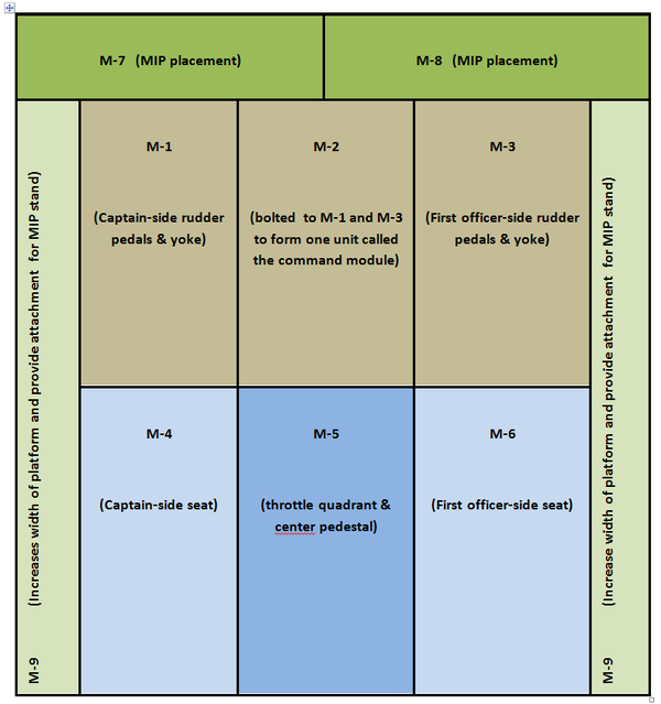
BELOW:  Diagram layout of modular design.


Update

on 2016-07-19 23:25 by FLAPS 2 APPROACH

Several individuals have requested the dimensions of the platform, which is smaller than a standard platform.  The benefit on being modular is that you can easily add sections to the platform to increase its size.

Platform Size

  • Overall Length:  183 cm

  • Overall Width:  183 cm

  • Height:  16 cm

  • Module M7: Overall Length: 183 cm (each piece left and right is 83.5 cm in length)

  • Module M7: Width 15.5 cm

  • Module M9: Length 167 cm

  • Module M9: Width 15.5 cm

  • Module M1, M2 & M3: Length 85 cm

  • Module M1, M2 & M3: Width 53 cm

  • Module M4, M5 & M6:  Length 81 cm

  • Module M4, M5 & M6:  Width 53 cm

If you are attempting to accommodate a OEM 737 column linking mechanism, the height of the platform will need to be considerably higher (in the order of 10-12 inches height) to house the lower cog mechanism of the columns.

Sheepskin Seat Cover added to Weber Captain-side Seat

sheepskin seat cover added to oem weber seat

Sometime ago I acquired a pair of Weber pilot seats which came with the correct Boeing diamond-pattern, grey honeycomb seat covers.  However, one of the seat covers was slightly damaged.  The lower cover was also a tad on the small side and kept popping off the rear section of the lower cushion when you sat on it.  Not a major problem, but it was slowly becoming irritating having to repeatedly attach the cover back on the cushion.

The small size was probably caused by the previous owner washing the seat cover;  Boeing covers are renowned to shrink substantially when washed in hot water!  To rectify these minor problems, I decided to have the captain’s side upgraded to a sheepskin seat cover.

A friend of mine has access to high quality Boeing-style sheepskins and being a wizard at sewing, agreed to retrofit the cover for me.

It should be noted that sheepskin covers are not attached to the seat like you would do on an automobile.  Rather, the sheepskin is sewn directly onto the existing fabric of the original seat cover.  Colour varies somewhat depending upon the manufacturer awarded the Boeing contract, but in general they are grey to tan in colour.

I think you will agree, that the final outcome looks, and certainly feels, much better than the original damaged and too small seat cover.

B737-300 Throttle Full Automation Upgrade

oem 737-300 throttle formally used by South West Airlines. Note grey coloured throttle levers and raw aluminum handles. The boxes that contain the TOGA buttons can just be seen

The throttle quadrant installed in the simulator is from a 737-300.  When I initially  converted the throttle for flight simulator use, I choose to not have full automation included; automation being at the time fraught with issues in relation to correct and accurate operation.  

Technology rarely remains stationary and after one year of operation I’ve been reliably informed that automation can now be implemented without the problems previously experienced.  Therefore, I’ve crated the throttle quadrant and it’s now on its way to the US via DHL courier for conversion to full automation.  A process I am told that will take a few weeks.

Automation will include, at the minimum, the following:

  • 4 speed trim wheels dependent upon aircraft status (as in the real aircraft)

  • Accurate trim tab movement

  • 9 point speed brake (speed brake operation as in the real aircraft)

  • Full automation of throttle thrust handles as per MCP speed window and/or CDU

  • Hand brake release by depressing brake pedals (as in the real aircraft)

I don’t mind admitting that that my building abilities don't include complete knowledge on how to convert a 737 throttle correctly - especially in relation to automation; therefore, this task has been outsourced.

The method in which automation will be achieved is slightly different from the usual way throttles are converted, and includes some magic programming of chip sets and machining of parts to allow compatibly with ProSim737.  Taking into account Christmas and New Year, I'm hoping that the machining, installation, configuration and testing will be completed by January (2013) and the throttle will be re-installed into the simulator by February.

In a future post, I will explain the process of conversion, and how automation has been achieved with minimal use of add-on software.

Idle Time

Although the throttle quadrant and pedestal will be absent from the simulator for a short time, work will not be idle.  The conversion of the twin real B737 yokes and columns has been completed and I'm finalising installation of the second platform which incorporates linked 737 rudder pedals.  I am hoping this will be completed by mid-November.  I have discussed the new platform in a previous post.

Converting Genuine B737 Audio Control Panels (ACPs)

oem 737-400 ACP. this will be a filler until two next generation ACPs are found

I have looked at several commercially made Audio Control Panels that are available for connection to flight simulator – I did not like any of them.  They all seemed to lack a certain degree of authenticity, whether it was the LED backlighting rather than bulbs, poorly designed and moulded switches, or out of alignment cheap-looking plastic buttons.  The only ACP units that interested me where those produced by Flight Deck Solutions, however, the price for two units was greater than purchasing two genuine second-hand ACP units. 

What is an ACP

ACP stands for Audio Control Panel and the B737 has three units; one in the aft overhead and two (captain & first officer) in the center pedestal.   Each panel controls an independent crew station audio system and allows the crew member to select the desired radios, navigation aids, interphones, and PA systems for monitoring and transmission. Receiver switches select the systems to be monitored.  Any combination of systems may be selected. Receiver switches also control the volume for the headset and speaker at the related crew stations. Audio from each ACP is monitored using a headset/headphones or the related pilot’s speaker.

Simply, the ACP is a glorified sound mixer.

Finding second-hand ACP units from a B737-800NG is next to impossible, so the next best thing are units removed classic series 737s.  The units I am using were manufactured by Gables Engineering in 2004 and have been removed from a B737-500.  It is unlikely that ACP units from an earlier series aircraft would be used in the NG, as the NG ACP unit design is different.  But, for a home-made simulator the use of older ACP units fulfils the same roll and is a very good stop-gap until a OEM NG panel can be procured.

When you begin to search for ACP units, you will discover there are a large number of different designs available.  The design can be correlated to the era of the unit.  Earlier units used sliders and turn dials while later models utilised push buttons.   Many of the slider-style units were used in 727s. 

Conversion of ACP Unit to Flight Simulator - Several Methods

It is difficult to document exactly how a conversion is done.  There are many variables to consider and genuine parts and flight simulator set-ups can be different.  By far the most challenging task is determining which wire from the 55 pin plug controls which ACP function.

oem 737-400 ACP unit with outer shell removed.  Most of this will be removed with the exception of the switches.  The wiring can be removed and replaced or unraveled and used directly

Removing Unwanted Wiring

You can either start afresh and after removing the outer aluminium casing, strip most of the wiring from the unit, along with discarding unwanted solenoids, relays and the large circular 55 pin plug at the rear of the unit; or keep the wiring and 55 pin plug and attempt to determine which wire goes where and and connects with what function. 

When finished removing much of the unwanted interior you will be left an almost empty container and some hardware and electrical circuits (buttons and switches).  Most of the switches are triple push switches and you must be careful to not damage the internal mechanism of these switches.

Which Wire Goes Where and Connections

There are two ways to convert the unit:  The first is to use existing wiring and determine which wire goes to what button/switch to reflect whatever functionality; this can be a time-consuming, challenging and frustrating task.  Once the wire to a function has been found, you must identify the wire with a flat tab or other physical marking device.  Each wire is then directed to an interface card.

The second method is a little easier.  Remove all the wires are rewire the unit.  This way there is no double-guessing that you have the correct wire.

If you have opted for the slightly easier second method of removing all the wiring from the unit and starting afresh, you can now recycle the same wire and solder the wires to the appropriate switches.  Recycling in motion :)

Determining Functionality

One method to determine functionality is to use a digital multi meter.  Set the meter to either continuity or resistance, select a wire connected to a switch and place the probe at the open end of the wire.  Identifying the correct wire/switch will cause the meter to either emit an audible beep or display a resistance on the display.  This is the wire that connects this function.

Once the wires have been identified and connected to the correct hardware switches within the ACP unit, they are then connected to an interface card.  I have used a Leo Bodnar BU0836X card which has available a large number of inputs and outputs. 

The Leo Bodnar card provides the interface between the ACP units and flight simulator.

To keep the wiring tidy, bundle the wires into a wiring lumen terminating in a solid plug / connector.  In my case I've used a standard style 18 pin computer connector. 

It is important to use a plug, rather direct the wires directly to the interface card, as you may wish to remove the ACP units at some stage.  A plug allows easy removal and connection.

Leo Bodnar card and two wire rails connected to acyclic board.  The vertically mounted wire rail provides a strong support from which to solder the wires.  The two computer plugs connect to the rear of each ACP unit.  The other small blue coloured card is an FDS power connection card used to daisy chain 5 Volt  power to the FDS modules I am using

Wiring Harness, Rail and Backlighting

A wiring harness was constructed to facilitate easier connection of the wires from the ACP units to the interface card. The harness and Leo Bodnar card is attached to a thick piece of acrylic plastic which in turn was mounted to a piece of wood that fits snugly within the center pedestal.

Wire Rail

Each ACP unit has a dedicated 'wire rail' attached to an acrylic plastic base.  The purpose of this rail is to provide an interface between the ACP units and the Leo Bodnar card.  Whilst this interface is not absolutely necessary, it does allow for identification of the wires (numbering system seen in photograph above).  Furthermore, it also provides a stable and solid base to secure wires between the interface card and each of the ACP units.

It should be noted that the rail also acts as a Y-junction to filter the outputs from two ACP units into one, which connects to the interface card and flight simulator.

The wires from the rail are then soldered to a standard style computer plug which connects to its male  equivalent mounted to the rear of each ACP unit. In essence we have three parts to the system:

  1. A re-wired ACP unit with wires terminating in a plug on the rear of the unit. 

  2. A wire rail which sits between the two ACP units and the interface card (Y-junction).

  3. An interface card that  connect with the wire rail and then to flight simulator via a USB cable.

Soft amber glow of ACP unit back lighting at night.  The light plates of genuine units always use globes rather than LED lights.  Power is 5 Volts DC and the amperage draw is around 1 AMP

Backlighting

The wires which carry power to illuminate the back lighting are wired directly from the light plates located in each ACP unit to a small electrical terminal block mounted to the rear of the unit.  The power wire is then directed to the panel light switch, located on the center pedestal. 

The panel light switch, located on the center pedestal,  controls back-lighting to the throttle quadrant, center pedestal and to the trip indicators on the yokes.  The reason for breaking this power wire with a two-wire terminal block is to allow removal of the ACP unit if necessary.  If you wanted to, you could use a pencil style audio push-in style plug.

A single USB cable from the Leo Bodnar card connects the ACP units to the main FS computer.

Synchronised Units - Limiting FSX Factor

In a real aircraft each ACP unit is separate to each other and can be configured independently, however, flight simulator (FSX) falls short in this area and uses only one ACP unit to mimic button presses across all units. As such, it was pointless to wire each unit separately and independent of each other.  Therefore, both ACP units mimic each other in functionality and output. 

For example, the ADF1 button can be pressed on the captain-side ACP unit to turn ADF1 on.  If you then press the same button on the flight officer side unit, ADF1 will be turned off.  This is another reason why a wire rail, mentioned above, was used; to act as a Y-junction.

NOTE (January 2015): ProSim737 now allows configuration of all buttons on the Captain and First Officer ACP units.  ProSim737 now allows independent selection of an ACP unit (up to three) removing the earlier FSX-imposed limiting factor.  Both units have been re-wired to take this into account.

Converted ACP unit showing replacement wiring and 18 pin computer style plug.  The circular hole in the rear below the plug is where the 55 pin plug was removed

Control - Captain or First Officer

Some enthusiasts wire units so that the Captain side is always the main controlling unit.  In my set-up, the wires from each ACP unit are fixed to the 'wire rail' and then to the Leo Bodnar card.  This allows you to be able to choice either side as the controlling unit.  The downfall being that whatever side is not in control must have the correct buttons pre-selected for correct operation.

Ingenious Design

One very interesting aspect of the ACP units is how Gables Manufacturing has designed the buttons to illuminate light when activated.  I initially thought that each button would have a separate bulb; however, this is incorrect.  The light which illuminates a button when engaged, comes directly from a number of strategically positioned bulbs.  An ingenious design incorporates a small reflector dish similar to an old style camera flash unit, to stop light reaching the button when it is in the unengaged position.  Engaging the button moves the dish into alignment which reflects back light into the button’s clear acrylic interior.  

Although an ingenious design, you must be very careful if handling a button to ensure that the reflector, which is positioned between the base of the button and light plate, does not 'bounce' away to be lost.

Configuring Functionality

Configuring ACP functionality, once the wiring is correctly connected, is straightforward and can either be done directly through the control panel in FSX, through FSUIPC or directly from within ProSim737.

The pencil-style and square-type buttons of each ACP unit allow quite a bit of functionality to be programmed when using FSUIPC.  Not every ACP feature, used in a real aircraft is replicated in flight simulator; therefore, those buttons not used for essential audio functions can be used for other customised functions.  

The most important functions (in my opinion) to have working are the indents for: VHF, NAV 1/2, ADF 1/2, MRKS (markers) and DME.  COM 1/2 transmit buttons can also be configured easily in FSUPIC to use  when flying on VATSIM or IVAO.

I have not configured the audio (volume) on the pencil-style buttons; however, it may be possible to configure these at some later stage using a separate sound card.  I believe the potentiometers  range from 11.90 - 12.00 K Ohms.

Aesthetics

I think you will agree that the OEM ACP units, even if not NG style, look much better than replicated modules – even if they are not the latest NG style:  the genuine buttons and switches, the soft amber glow of real Boeing back-lighting, and the substantial build of the units generate a high level of immersion.

NG Style ACP Units

The units are not NG style, however, as New Generation parts come on-line, I will replace these units with the more modern style.  it iss just a matter of waiting for 600 and 700 series units to become available.

I've compiled a short video using Ken Burns effect.


737-500 ACP conversion (Ken Burns effect)


POST SCRIPT - An Easier Method: Schematics to ACP Units and 55 Pin Outs

At the time of my conversion, I did not have available a schematic showing the pin outs for the ACP unit.  This meant any conversion had to be done from scratch (as documented above). 

I now am in  possession of the ACP schematic diagram, which includes a pin out diagram indicating what function each pin of the available 55 pins on the rear plug connects to. 

diagram !: standard 55 pin plug found on Gables ACP units

If another conversion is required, the wiring will be a lot simpler as the wires will not need to be striped from the unit and re-done.  All that will be needed is to attach wires from the Leo Bodnar card directly to the 55 pin electrical plug already mounted on the rear of each ACP unit (I have been reliably informed, that thin 1mm copper pipes obtainable from modelling supplies fit perfectly), and connect the light plates to a 5 Volt DC power source. 

Minor Complications

At first, using the 55 pin plug appears to be an easy method of conversion, however, there is a minor set-back.  The COM radio cannot be connected; it is probable that on the real aircraft the MIC selectors are routed via onboard amplifiers rather than via the plug.  Therefore, if these functions are required, they will need to be converted by rewiring and connecting to a accessory plug of some type (as has been done documented in the first section of this post).

Do Not Reinvent The Wheel - Canon Plugs

It is important to always try and convert any OEM part using the Canon plugs and pin outs before rewiring any part.  Gables have already done an excellent job  wiring the panel internally, so why not utilise this wiring by using the existing Canon plug system.

This ACP panel is the only panel that has been converted this way in the simulator.  It was the first panel that was converted and at the time I did not understand the Canon plug concept in its entirety.  All other panels have been converted using the existing plug system avoiding rewiring the unit.

Update

on 2020-07-05 01:50 by FLAPS 2 APPROACH

One minor problem observed using the standard Leo Bodnar interface card, is that the connection of the wires into the card kept working their way loose, resulting in a break in the connection.  This problem identified itself by giving incorrect button designations on the ACP units.  No matter how hard I pushed the wires into the holders on the card, the wires eventually worked their way out a tad.

To solve this issue, I replaced the BUO836X card with the Leo Bodnar BBI-32 Button Box card.  The BB1-32 card allows the wires to be soldered in place.

Update

on 2015-07-30 06:20 by FLAPS 2 APPROACH

Following on with converting as many units to be 'plug and play', the ACP units were once again revamped to allow the Leo Bodnar card to be installed inside the Captain-side unit. 

Captain-side master ACP showing reworked connectors.  One straight-through cable connects between the master and the F/O ACP (slave) while the other cable connects with its mate inside the pedestal bay.  The USB cable connects with a USB hub located in the pedestal.  If I was converting the ACP units again, I would definitely use Canon plugs

The Captain-side ACP is the 'command' unit and the F/O ACP units acts as a 'slave'.  A straight-through cable connects both units via D-sub plugs (the computer-style terminal plugs were removed).   A single USB cable connects the Captain-side ACP to the computer. 

Further, the limiting aspect of having to have the F/O side activated to allow functionality to occur on the Captain side has been removed.  Historically, FSX has only allowed the ACP units to operate from the Captain side.  ProSim737 enables operation of three ACP units, so this limiting factor is now removed. Each button on both ACP units has been wired to allow separate control.

The benefit of installing the joystick card inside the unit is it removes the large amount of wiring that  previously used valuable real estate space within the center pedestal.  

Update

on 2022-05-09 12:26 by FLAPS 2 APPROACH

This conversion was completed sometime ago (2014-15).  Today (2020) there are more efficient and easier ways to convert the ACP units that do not require the unit to be completed gutted.  Certainly, the outcome is identical, but the method different.

If converting another ACP unit, I would not use the method documented above.

Using Genuine B737 Aviation Parts

A colleague grinding the tails from genuine DZUS fasteners. These will then be attached to reproduction modules to enhance their appearance

There is something fundamentally different when using a genuine piece of aircraft equipment instead of a replicated item – It’s difficult to define, but the idea of using a piece of hardware that flew thousands of flight hours, in good and bad weather, has a certain appeal.

You will notice when you peruse the below list that many parts are not Next Generation, but are from classic 737 airframes, Finding Next Generation components is time consuming and can have long lead times. In the interim, I am using classic parts as fillers. Fortunately, some components used in the classics, especially the 737-500 are also used in the Next Generation.

The following OEM parts are currently used and converted:

  • 737-500 yokes and columns (2)

  • 737 Captain-side stick shaker

  • 737-300 throttle quadrant

  • 737-300 telephone and microphone

  • Jetliner style aviation headset (was formally used in an United B737)

  • 737-300 three-bay center pedestal

  • 737-400 fire suppression panel

  • 737 yoke trip indicators (2)

  • 737 rudder pedals (2)

  • 737-500 audio control panels (2)

  • 737 Weber captain and first officer seats

  • MD-80 clock (flight officer side of MIP)

  • 737 overhead map light

  • 737 korry switches

  • 737-500 tiller handle

  • 737-300 Forward & Aft Overhead Panel w/ Coles engine switches & genuine light switches

  • DZUS fasteners

  • 737-800 flap guage

  • 737-800 Yaw Dampener gauge

  • 737-800 brake pressure gauge

I would like very much like to replace the ADF and NAV modules with OEM panels; however, need to research the feasibility in doing this.  In the meantime, I’m using reproduction navigation radios manufactured by Flight Deck Solutions.

Historical Significance

The historical significance of using genuine parts cannot be ignored.    It’s relatively easy to research an aircraft frame number or registration number and in the process learn where the aircraft was used and in what conditions.  

For example, the throttle unit I am using was removed from a South West B737-300 that plied the continental USA for many years, whilst the yokes and columns were previously used in a B737-500 operated by Croatian Airlines.  The clock I have for the flight officer side of the MIP came from a FedEx MD80 and one of the ACP units was used by Aloha Airlines in Hawaii.

Recycling

Using OEM used parts helps the environment!  

For a start, you are not purchasing new reproduction parts made from virgin resources.  Secondly, the used parts you bought probably would have been destined for expensive recycling, or alternatively disposed of to landfill.  

Recycling can be fun!!  

It’s a good feeling to convert something destined for disposal and bring it back to life.

Toughness

One of the major benefits of using OEM aircraft parts is their longevity and ruggedness.  Whilst none of us want to damage our simulators through over zealous use; it can and does occur from time to time.  Replica parts are – well a little delicate.  To ensure long life you must treat them with care.  

It’s the opposite with genuine aircraft parts; damaging a genuine part with normal use is almost impossible.  

For example, a speed brake lever is relatively easy to bend or break on any number of replica throttle quadrants on the market; damaging a genuine speed brake handle is very difficult as they are constructed from high grade materials to withstand genuine stresses (pilot-driven or otherwise).

Simulation pilots are often as rough on their gear as genuine pilots are; I’ve seen simmers jab ACP buttons with enough force to break a piece of plastic.  Genuine buttons are made to withstand this heavy-handed treatment, replica parts – break!

Aesthetics – Look Your Best

It’s a fact; aN oem aircraft part looks 100% more realistic than a simulated part – that’s obvious.  If your center pedestal has an assortment of genuine modules mixed in with replica modules, the pedestal will appear much more authentic than one comprised solely of simulated units.

You will be surprised that small things can make a huge aesthetic difference.  Take for example, DZUS fasteners.  I bought a box of fasteners sometime back and use them wherever I can to replace the reproduction fasteners or screws that many manufacturer’s use.  If the fastener does not fit the appropriate hole in the reproduction module, I either enlarge the hole with a drill bit, or if this isn’t feasible, I cut the tail from the fastener leaving only the DZUS head.  I then use a piece of sticky blue tack or crazy glue to secure the DZUS head to the appropriate part.  

OEM B737-300 two-bay center pedestal showing mix of reproduction and oem components

The fasteners I've used were purchased second-hand; therefore, they show wear and tear.  I don’t mind this used and abused look.  Yes it sounds rough and ready, but the end result looks very pleasing to the eye and more faithful to what you would see in an operational flight deck.

The confines of the flight deck are not as clean as one might expect, and instruments are scratched and dented; pilots rarely concern themselves with aesthetics and technicians complete their maintenance quickly, as an aircraft not flying equates to lost revenue for the airline.

The use of genuine parts adds to the immersion factor, and as a Dutch simmer recently commented: “It makes the simulator more alive”

Availability of Parts

oem aircraft parts can be difficult to find and it’s a hit and miss affair.  As newer aircraft are brought online, airlines scrap their older fleet and parts become readily available.   

Finding late model Next Generation parts, at a reasonable price is almost impossible; these parts are still serviceable.  Parts in older aircraft may also be serviceable; however, they must meet safety regulations and be inspected and approved by a certified agency.  This process is expensive and many airlines find it cost prohibitive; therefore, parts are sold as scrap.

E-Bay can be a good place to find parts.  Search for aviation parts - Boeing, 737 or Gables.  Aviation scrap yards are also invaluable, as are the classified sections in various flight simulation forums on the Internet such as My Cockpit and Cockpit Builders.

Conversion - Use in Flight Simulator

This can be minefield to the uninitiated.

OEM parts often operate on a variety of voltages, and it’s not uncommon to need 5, 12, 18 and 24 Volt power supplies to enable an OEM part to work correctly.  Further, the wiring inside the neat-looking box can be a rat’s nest of thin wires weaving their way to and from a variety of unidentified pieces, before terminating in an electrical connection rarely found outside the aviation industry (Canon plug).

I am not an expert in conversions (although I am learning quickly.....).  I’m lucky in that I have access to a few people who are very knowledgeable in this area and are happy to share their knowledge with me.  

Interfacing

There are a number of ways to interface an OEM part with flight simulator.  The easiest is to use is a Leo Bodnar BU0836 joystick card, or similar, using standard flight simulator commands and/or FSUIPC.  The use of these cards makes assigning functionality in flight simulator very easy and straightforward.

One BU0836 card provides 12 inputs which correlates to 12 individual switches or buttons.  The 0836 card also has the capability to have a matrix constructed which increases the number of available outputs.  Another joystick card that is very good and easy to configure is the PoKeys card.

The inside of a 737-500 ACP module showing the rat’s nest of wiring that can be found within an OEM module

For functionality that requires movement, a servo motor will need to be used and configured in FS2Phidgets.  Phidgets allow you to program almost any moving part, such as the needle of the rudder trim module or the trim wheels of a throttle unit.    Digital servos are better than analogue servos as the former do not make an audible squeaking noise when connected to power.

By far, the most difficult part of any conversion is discovering what wire connects to what functionality.  Finding the wire can be challenging in itself as most avionics modules are a nest of wires, diodes and electronic circuitry.

You Have A Choice

You don’t have to use reproduction simulator parts throughout your flight deck – there is a wide selection of used aviation parts available, and with a little searching, you probably can find what you want.  

OEM parts frequently can be found at far less cost than their reproduction counterparts, and in every case will always look more visually appealing.  If you’re not up to the task of conversion, there are individuals that can convert modules for you.  You will then need to configure the functionality in FSUIPC or directly in the avionics suite used.  At the very minimum, using DZUS fasteners will bring your simulator to the next level of realism.  But be warned, using OEM parts evokes a desire to replace anything replica with something real.

In my next post we will look at converting two genuine B737 Audio Control Panels (ACPs) to flight simulator use.

Ground Effect - Historical Perspective & Technical Explanation

During the Second World War, a crippled Boeing B17 was struggling to maintain altitude.  The aircraft and eleven crew members were over occupied Europe, returning to England, following a successful bombing mission.

Searchlights, Flak & Enemy Fighters

After negotiating the enemy searchlights that probed the darkness over their target, and then being struck by shell fragments from anti-aircraft flak, they were pounced upon by German fighters on their homeward leg.  The ensuring fight was dramatic and left the damaged bomber with only two engines running and third engine having difficulty.  As the bomber approached France, the enemy fighters, starved of fuel, aborted their repetitive attacks, but the damage had been done.  Loosing airspeed and altitude the aircraft could not maintain contact with the Bomb Group; soon they were alone.

The captain, in an attempt to maintain altitude, requested that everything heavy be jettisoned from the aircraft.  This included machine guns, ammunition and damaged radio equipment; soon the B17 was a flying skeleton if its former self.

The Captain was concerned that a fire may develop in engine number three as it was spluttering due to a fuel problem.  The Captain did not need to concern himself much longer, for the engine began to cough uncontrollably before vibrating and ceasing to function.   The aircraft was now only flying on one engine – something not recommended, as it placed great strain on the engine and aircraft superstructure.  

The aircraft continued to loose altitude despite the jettisoning of unwanted equipment.  The Captain decided it was better to ditch into the English Channel rather than land in occupied France.  His thinking was that Air Sea Rescue maybe able to pick them up, if their repeated morse code (SOS) had been received by England.  The power of one engine was nowhere enough to maintain such a large and heavy aircraft and the crew prepared to ditch into the freezing cold water of the channel.

We’re Going In – Good Luck Boys!

“Get ready guys, we’re 300 feet above the water” yelled the Captain into his intercom system.  “As soon as we hit bust them bubbles and get out.  Try to get a raft afloat”.  “Link up in the water  – Good Luck!”

Everyone expected the worse.  Surviving a ditching was one thing, but surviving in the cold water of the English Channel in winter was another!  The rear gunner, since moving forward sat close to escape hatch and gingerly rubbed his rabbit’s foot; he had carried this on every mission.  The side gunner fumbled repeatedly with his “lucky” rubber band, the bombardier sat in private thoughts, a photograph of his loved one held tightly in his hand, and the navigator frantically punched his morse set trying to get the last message out before fate took command of the situation.

The aircraft, although trimmed correctly, slowly began to dip towards the sea.  But at 60 odd feet above the waves, the aircraft began to float  – it felt as if the aircraft was gliding on a thermal.  For some reason the aircraft didn't wish to descend.  The remaining engine screamed its protest at being run at full throttle, however the horizontal glide continued. 

The Captain was amazed and thankful for whatever was keeping this large aircraft from crashing into the sea.  It was as if the B17 was cruising on a magic carpet of air – why didn’t it crash.  

A tail-wind assisted in pushing the B17 toward England and safety; seeing the English coast in sight, the navigator quickly calculated a route to the nearest airfield closest to the coast.  Twenty minutes later the bomber lumbered over the runway.  The only way to land was to reduce power to the remaining engine and push the control wheel forward, thereby lowering the pitch angle.  They were home and safe!

Divine Interaction, Luck, or Skill ?

The crew thought it was divine interaction that the bomber had not crashed – or perhaps luck!

Aviation engineers were baffled to what had occurred.  The aircraft had glided many miles above the surface of the English Channel and had not crashed.  Boeing, in an attempt to unravel what had occurred, repeated the event in the confines of a wind tunnel, to realize that what had maintained the large aircraft airborne was not divine interaction, but the interaction of what has since been termed Ground Effect.

The above account, although embellished in detail, did occur.  The mishaps of this bomber during the Second World War demonstrated a previously unknown phenomenon - Ground Effect.

Ground Effect – Technical Explanation

Ground effect refers to the increased lift and decreased drag that an aircraft wing generates when an aircraft is about one wing-span's length or less over the ground (or surface).  The effect of ground effect is likened to floating above the ground - especially when landing.

When an aircraft is flying at an altitude that is approximately at, or below the same length of the aircraft's wingspan, there is, depending on airfoil and aircraft design, a noticeable ground effect. This is caused primarily by the ground interrupting the wingtip vortices, and the down wash behind the wing. 

diagram 1: ground effect in the air

When a wing is flown very close to the ground, wingtip vortices are unable to form effectively due to the obstruction of the ground. The result is lower induced drag, which increases the speed and lift of the aircraft.

The two diagrams depict aircraft in ground effect whilst on the ground and in the air.

diagram 2: ground effect on the ground

A wing generates lift, in part, due to the difference in air pressure gradients between the upper and lower wing surfaces. During normal flight, the upper wing surface experiences reduced static air pressure and the lower surface comparatively higher static air pressure. These air pressure differences also accelerate the mass of air downwards.  Flying close to a surface increases air pressure on the lower wing surface, known as the ram or cushion effect, and thereby improves the aircraft lift-to-drag ratio.  As the wing gets lower to the surface (the ground), the ground effect becomes more pronounced.

While in the ground effect, the wing will require a lower angle of attack to produce the same amount of lift. If the angle of attack and velocity remain constant, an increase in the lift coefficient will result, which accounts for the floating effect. Ground effect will also alter thrust versus velocity, in that reducing induced drag will require less thrust to maintain the same velocity.

The best way to describe ground effect and which many people, both pilots and passengers, have encountered is the floating effect during the landing flare.

Low winged aircraft are more affected by ground effect than high wing aircraft. Due to the change in up-wash, down-wash, and wingtip vortices there may be errors in the airspeed system while in ground effect due to changes in the local pressure at the static source.

Another important issue regarding ground effect is that the makeup of the surface directly affects the intensity; this is to say that a concrete or other hard surface will produce more interference than a grass or water surface.

Problems Associated With Ground Effect

Take Off

Ground effect should be taken into account when a take-off from a short runway is planned, the aircraft is loaded to maximum weight, or the ambient temperature is high (hot).

Although ground effect may allow the airplane to become airborne at a speed that is below the recommended take-off speed, climb performance will be less than optimal.  Ground effect may allow an overloaded aircraft to fly at shorter take off distances and at lower engine thrust than normal.  However, the aircraft will not have the ability to climb out of ground effect and eventually will cease to fly, or hit something after the runway length is exceeded.

Approach and Landing

As the airplane descends on approach and enters ground effect, the pilot experiences a floating sensation which is a result from the increased lift and decreased induced drag value. Less drag also means a lack of deceleration and could become a problem on short runways were roll-out distance is limited.

Therefore, it's important that power is throttled back as soon as the airplane is flared over the threshold and the weight of the airplane is transferred from the wings to the wheels as soon as possible.

How to Counter Ground Effect

To minimise ground effect on landing, the following must be addressed:

  • Pitch angle should be reduced to maintain a shallow decent (reduces ability of the wing to produce more lift).

  • Thrust should be decreased.

  • The power should be throttled back as you cross the threshold at ~RA 50 feet (note that in simulation ~10-15 feet is more effective).

  • Land the aircraft onto the runway with purpose and determination.  Do not try and grease the aircraft to the runway (often called a carpet landing).  The weight of the aircraft must be transferred to the wheels as soon as possible to aid in tyre adhesion to the runway (also important when landing in wet conditions).

Does Ground Effect Occur in Flight Simulator?

If the aircraft is not set-up correctly, ground effect will definitely be experienced in a flight simulator. 

If you have ever wondered why, after reducing speed on an otherwise perfect approach, your aircraft appears to be floating down the runway, then you have already experienced ground effect.

List of B737 Carriers Worldwide - Interesting....

first boeing 727. lufthansa 1968

A Boeing 737 takes off or lands somewhere in the world on average every 5 seconds!

To date, the Boeing series of airliners is the most successful airliner the world has seen.  Boeing's success revolves around, amongst other things, the ability to be able to upgrade their aircraft from a basic overall design that has changed little since the first 727 rolled out of the hanger in the 1968, earmarked for the German airline Lufthansa.

So which nations place their trust in Boeing?  This link provides a list of worldwide carriers by nation.

Creating Waypoints on the Fly with the CDU

Often you need to inject into the flight plan a Place Bearing Waypoint or an Along Track Waypoint.  There are several ways to do this with each method being similar, but used in differing circumstances.  Depending upon the FMC software in use, either the LEGS or the FIX page is used.

A Place Bearing Waypoint (PBW) is a waypoint along a defined bearing (radial) that is created at a specified distance from a known waypoint or navigation aid (navaid).  A PBW is used to create  a waypoint that is not in the active route.

An Along Track Waypoint (ATW) is a waypoint inserted into a route that falls either before or after a known waypoint or navaid.

Although the PBW and ATW are similar, they are used in differing circumstances.

  • In the following examples I will use the waypoint TETRA as an example.  TETRA is a waypoint near Narita, Japan (RJAA).

Creating a Place Bearing Waypoint

  • Type into the scratchpad the waypoint name, bearing and distance.

    For example, type into the scratchpad a TETRA340/10.  TETRA is the waypoint that we want to create the new waypoint from.  This is called an anchor waypoint.  340 is the bearing in degrees from the anchor waypoint that the new waypoint will be generated.  10 is the distance in nautical miles from the anchor waypoint that the waypoint will be generated at.

  • Up-select TETRA340/10 to the LEGS page. 

  • Press EXECUTE.

To insert the waypoint before the anchor waypoint use the negative key (TETRA340/-10).  Do not use the negative symbol if you want to insert the waypoint after the anchor waypoint (TETRA340/10).  Take note that the slash (/) is after the bearing and the waypoint name and vector are joined with no spaces.

Creating an Along Track Waypoint

  1. Type into the scratchpad the waypoint or navaid that will be used as an anchor waypoint.

  2. Up-select this into the correct line of the route in the LEGS page.

  3. Press EXECUTE.

Important Points:

  • If the waypoint is already part of the route, it is not necessary to type the identifier in to the scratchpad.  Rather, press the appropriate Line Select Key adjacent to the identifier (in the LEGS page) to down select to the scratchpad.  Then add the /-10 or /20 after the identifier and up-select.  Using this method eliminates the possibility of typing the incorrect identifier into the scratchpad.

  • The FMC software will generate subsequent waypoints with a generic name and numerical sequence identifier.  For example, TETRA, TETRA01, TETRA02, TETRA03.

Creating a Circle around a Waypoint using the FIX Functionality

The purpose of creating a circle (ring) around a point in space is to increase spatial awareness when looking at the Navigation Display (ND).  A circle at a set distance may be used to define the Missed Approach Altitude (MAA), the distance from the runway threshold that the landing gear should be lowered, or to designate an important waypoint.

I nearly always use two or three circles depending upon the approach being executed.  One circle will be at 12 miles while the second circle will be at 7 miles.  The use of circles can be very helpful when flying a circle-to-land approach; one circle will define the MAA and the other circle will define the  'protected area' surrounding an airport.

To create a circle (ring) around a known point

  1. Press FIX on the CDU to open the FIX page.

  2. Type into the scratchpad, the name of the waypoint or navigation aid (VOR, NDB, etc).  For example TETRA.

  3. Up-select this to the FIX page (LSK1L).

This will display a small circle around the identifier in the Navigation Display in green-dashed lines.

If you want the circle to be at a specific distance from the point in question.

  1. Type into the scratchpad the distance you require the circle to be drawn around the waypoint.  For example /5.

  2. Up-select this to the FIX page (LSL2L).

To add additional circles around the selected point, repeat the process using different distances and up-select to the next line in the FIX page.

Important Point:

  • A quick way to insert a waypoint from a route into the FIX page is to press the waypoint name in the LEGS page.  This will down select the waypoint to the scratchpad saving you the time typing the name and removing the possibility of typing the incorrect letters.  Up-select to the FIX page.

Creating a Single Along Track Waypoint (at the edge of the circle)

One or more waypoints can be created anywhere along the circumference of the circle (discussed earlier) by inserting a bearing and distance into the FMC page.  

To create a waypoint at the edge of the circle

Create a circle around a point as discussed earlier (TETRA).

  1. Type in the scratchpad the bearing and distance that you wish the new waypoint to be created (for example 145/5).

  2. Up-select this information to the FIX page (LSK2L). This will place a green-coloured line on the 145 degree radial from the waypoint (TETRA) that intersects a circle at 5 miles on the ND.

  3. Next, select the 145/5 entry from the FIX page (press LSK2L).  This will copy the information to the scratchpad.  Note the custom-generated name – TETRA145/5.

  4. Open the LEGS page and up-select the copied information to the route.  Note that TETRA145/5 will now have an amended name – TET01.

  5. Copy TET01 to the scratchpad.

  6. Open a new FIX page (there are 6 FIX pages that can be used).  Up-select TET01 to the FIX page (LKL1L).  This will create a small circle around TET01 on the ND.

  7. To remove the waypoint (TET01) from the route (if desired), open the LEGS page and delete the entry.   If desired, the waypoint can easily be added again to the route from the FIX page.

The above appears very convoluted, however once practiced a few times it becomes straightforward.  There is a less convoluted way to do this, however, the method is not supported by ProSim737.

Inserting an Additional Along Track Waypoint around the Arc of the Circle (DME Arc)

A DME arc is a series of Along Track Waypoints that have been created along an arc at a set distance from the runway (waypoint or navigation fix).  This is often used when flying a NDB Approach.

Usually, the arc begins on the same bearing as the navigation track of the aircraft, and ends a set point, usually at the turn from base to final.  Subsequent bearings after the initial bearing are at a 30 degree spacing.

To create a DME Arc

First, ensure you have a circle created around the waypoint (TETRA) at the distance required (FIX page).

  1. Select the anchor waypoint (TETRA) for the arc from the LEGS page and down select it to the scratchpad.

  2. Type into scratchpad after TETRA (as separate entries) the bearing and distance.  For example: TETRA200/5, TETRA230/5, TETRA260/5, TETRA290/5 TETRA320/5 and so forth.  Note the bearings differ by 30 degrees.  This creates the arc.

  3. Up-select each of the above entries to the route in the LEGS page (after the anchor waypoint TETRA).

This will create an arc 5 miles from TETRA.

If you want the first waypoint to be along your navigation track, use the bearing for this initial waypoint as indicated in the LEGS page of the CDU.

The FIX page can also be used to create an arc using the same technique.  Using the FIX page will enable the arc to be seen on the ND, but not form part of the route.

Important Point:

  • It is important to note that user and along track waypoints are given a generic name and numerical sequence identifier by the FMC software (TETRA01, TETRA02. TETRA03, etc).

Understanding the CDU

What I have described above is but a very brief and basic overview of some functions that are easily performed by the CDU.

CDU operation can appear to be a complicated and convoluted procedure to the uninitiated.  However, with a little trail and error you will soon discover a multitude of uses.  It is important to remember, that there are often several ways to achieve the same outcome, and available procedures depend on which FMC software is in use.

I am not a professional writer, and documenting CDU procedures that is easily understood is challenging.  If this information interests you, I strongly recommend you purchase the FMC Guide written by Bill Bulfer.  Failing this, navigate to the video section of this website to view FMC tutorials.


Navigation display showing map view. Left to right.

image 1:  5 mile ring surrounding TETRA.

image 2: 2 and 5 mile ring surrounding TETRA.

image 3: 5 mile ring surrounding TETRA showing PBW on circumference TET01.

image 4: DME arc along circumference of 5 mile ring surrounding TETRA.


Acronyms

Anchor Waypoint – The waypoint from which additional waypoints are created from.

Bearing – Vector or radial.

CDU – Control Display Unit.

FMC – Flight Management Computer.

ND – Navigation Display.

Target Waypoint – The waypoint that has been generated as a sibling of the Anchor waypoint.

Waypoint – Navigation fix, usually an airport, VOR, NDB or similar.

  •  Updated 05 June 2022.

737-800 Primary Flight Display (PFD) Diagram

The simple to understand picture is an excellent visual reminder to the most important areas of the Primary Flight Display (PFD) in the 737-800.

When I was new to jets, I had this image printed in colour above the computer screen as a quick reference guide. It doesn't take long before it’s second nature and you no longer need to reference the diagram.

JetStream 738 by ProSim737 - Review

After flight testing several aircraft models, I decided to use the B738 (FS9 version) produced by Precision Manuals Development Group (PMDG).  This flight model, once the PMDG flight logic is removed, functioned exceptionally well and is very stable.   

One of the potential problems when using a flight model produced by another company is compatibility and functionality with your chosen avionics software suite.  Minor problems are often solved by tweaking the aircraft.cfg file; however, tweaks are just that, and often issues will occur which cannot be identified and rectified.  In my experience, tweaking the .cfg file may solve your initial problem, but may cause additional errors elsewhere.

Different Aircraft Models – Different Solutions

To ensure various aircraft models operate with their software, Sim Avionics provide users with specific aircraft.cfg files that correspond to the particular flight model they are using.  These files are optimally tweaked to the Sim Avionics software.

ProSim737 has handled the problem of aircraft model variances slightly differently.  Rather than provide a tweaked aircraft.cfg file to allow you to use whatever flight model you wished, they took a holistic approach and produced a complete aircraft dedicated ONLY to their avionics software suite.

Creating an aircraft model that is designed to only operate with their software has many advantages.  First and foremost is trouble-shooting.  Everyone is using the same software, meaning that if a problem does present itself, finding a solution is usually easier.  Chasing ghosts rarely occurs as the same company that produced the avionics suite produced the aircraft flight model.

At this stage, you may think that ProSim737 only works with their dedicated aircraft.  This is incorrect; ProSim737’s avionics suite will work with numerous aircraft models including the default FSX 737 and the PMDG FS9 737, however, if you want to achieve harmonious inter-connectivity with the avionics software, then using the dedicated flight model is highly recommended.

Hello JetStream 738

The JetStream aircraft is more a flight model than an actual virtual aircraft.  Don’t expect to see “wow” factor visuals with this model.  Instead, expect to experience “wow” factor flight dynamics that work in perfect unison with the flight avionics software.

Virtual pilots using a fully developed simulator often do not need what is offered in many aircraft models: virtual flight decks, pop-up gauges and GPS consoles are not necessary.  As such, the JetStream doesn’t provide these additives.  You will, however, see the default FSX panel layout of the B737.  This can easily be permanently removed by either editing the panel.cfg file or removing the panel images.  

Installation

The JetStream software comes with an .exe installer.  Installing is as easy as following the prompts.  When installed, a JetStream 738 folder will be found in the simobjects/aircraft folder.

JetStream Textures

The Jetstream uses the default texture pack belonging to the B737-800 FSX aircraft; therefore, the outside views mimic the same texture details seen on the default FSX model.  

I think the outside textures (especially with a repainted airline livery) are just as good as many payware add-on aircraft textures.  Certainly, PMDG NGX textures surpass the JetStream textures, but you must remember that the aircraft has NOT been designed as a pretty aircraft to look at, but a flight model to replicate defined flight dynamics.  Think of it as flying ones and zeros.

Video Makers & Virtual Airlines

Video-makers or those who wish to mimic a particular airline can easily re-texture the aircraft skin to reflect a specific colour scheme or airline livery.  Search through the ProSim737 forum and you will find several dozen repaints.  Installing additional textures is identical to the method used in FSX.

If you search this website you will find mention of the 164 liveries pack.  This pack provides many liveries and re-textures.

Outside Views & Animation

Many individuals concern themselves with the outside view of an aircraft.  Whilst it’s enjoyable to inspect the aircraft from the outside, the quality of the external visuals has absolutely nothing to do with the way the flight model behaves.                    

This said, the movement of essential equipment can be observed: the rudder, flaps, ailerons, spoilers and landing gear.  Landing and other outside lights are also replicated including a functional taxi light which is bright enough to “read by”.  The outside view is far from sterile.

Taxi Light – Too Bright & Intense

One downside to the external view is the actual positioning the taxi light.

Historically, Micro$oft have never animated the taxi light correctly.  ProSim737 have created their version of a taxi light, which is more a ball of light than a taxi light.

The taxi light is bright – very bright.  On lift off, the fall of the light beam covers the lower portion of the front screen view.  This obviously does not occur in a real aircraft.  Although I have not altered the files, I have been informed that this cosmetic issue can be rectified with a small tweak to the aircraft.cfg file.  

I would have liked ProSim737 to have developed the external lights from scratch with a dedicated taxi light with no fall off on the lower portion of the computer monitor.  Good external lights are essential if you fly predominately at night.

Flight Dynamics – flying Ones & Zeros

This is why the JetStream was developed – as a platform to replicate complicated flight dynamics to realistically mimic the movement and handling of a real jet aircraft.  This is where the wow factor begins and is where the JetStream leaves it’s contemporaries behind.

I am very impressed with the flight dynamics.  During several hours flight testing, the model was exceptionally stable, handled as you would expect, and interfaced with the ProSim737 logic flawlessly.  

Fine-Tuning & Stability Testing

ProSim737 has been designed to be operate with MCPs (Main Control Panel) manufactured by several companies.   I have been informed that, depending on the MCP type, problems can be experienced with the sensitivity of the auto pilot.  To alleviate this, ProSim737 allows the sensitivity of the MCP to be adjusted.

The JetStream manual suggests that a good method to determine possible over-control (i.e. oscillations) is to increase the simulation speed to 4x and observe if oscillations occur, and if the autopilot is able to hold either heading or altitude”.

I performed this stability test at x4 acceleration and noted very mild pivoting of the wings as the aircraft slewed along it defined navigation track.  When I morphed back to normal speed, the aircraft was in the same direction, attitude and altitude that it was when I entered acceleration mode.  Only at faster acceleration speeds (x16) did the aircraft loose position (which is to be expected).

Hardware Calibration

The JetStream requires careful and fastidious calibration of your yoke and rudder pedals to ensure solid performance.  

Calibration isn’t as important if you use the auto pilot to do most of your flying, however, if you prefer to hand fly to and from FL10, correct calibration of your yoke and rudder is paramount.

It’s essential to take the time to calibrate your hardware correctly using the Windows and FSX calibration tool, using FSUIPC to fine tune the results.

Your hardware control settings play a huge role in how the plane behaves, so before blaming the flight model, please test it with different controls and settings.  

The following is an excerpt from the JetStream read me file:

  • Most 738 models available represent a truly overpowered engine/dynamics ratio, The flight model tries to follow the real curve, don't expect it to reach high speed/AOA values as other flight models do, especially immediately after rotation.

  • As in FSX, nose-steering is nothing else but rudder, without FSUIPC's given steering routine and a hardware wheel, do not expect acceptable results on the ground.

  • The VC was deliberately removed from the model.

  • Trim related values do depend on hardware behaviour.  This relates to whether hardware has been calibrated with or without FSUIPC.

  • Idle N1 value is OAT dependent. You will get 20.7 at 15C.

  • Set General Realism Slider to Maximum! It is vital for the model!

PMDG (FS9) and Default 738 Verses JetStream

I outlined in the opening paragraph that ProSim737 can be used with several other add on aircraft, including the default FSX 738.  My limited testing proved that these aircraft fly well with ProSim737, however, nuisances do occur and tweaking of the aircraft .cfg file is needed to solve niggling problems with often undesirable outcomes..

The JetStream was designed from the bottom up to be the flight model for ProSim737.  Therefore, many of the nuisances observed when using other flight models do not exist.

As an example, the FS9 version of the  PMDG aircraft at Vr, with the yoke pulled to aft position, exhibits a slight delay of a second or two before actually lifting off the runway.  A positive rate is rarely achieved before V2 is called.  This is completely different with the JetStream which is far more responsive.  Pull back slightly on the yoke at Vr and the aircraft is airborne before reaching V2.

No matter what I did with the PMDG flight model, the only way to achieve rotation at Vr was to pull back on the yoke a few seconds before actually hearing the Vr call out.

This is but one example, illustrating why it’s solid sense to link a dedicated flight model to a specific avionics software suite to achieve harmonious integration.

FS Add Ons - Top Cat Compliant

Many virtual pilots use a popular add on flight tool called Top Cat.

Top Cat is used, amongst other things, to calculate weight, takeoff and landing performance.  The JetStream is compatible with Top Cat and the JetStream manual explains how to incorporate this advanced FS add on.

JetStream User Manual

A detailed user manual is included which is well written and informative.  It’s important to read this manual to ensure you get the most from the JetStream flight model.

Updates & Improvements

ProSim737 currently produces one aircraft and one avionics software suite.  While some may find this lacking, I find it reassuring.  Rather than become tired down to developing other aircraft and software, ProSim737 focus their attention on one aircraft – the B738.  This translates to regular updates and improvements which can only benefit the end user.

Support

Support is provided either by a dedicated forum or via personal e-mail communication.  

To date, all requests have been answered quickly and efficiently.  If you need help, support is available.  You are not left to feel as if you’re withering on a vine, waiting for assistance.

I try to be impartial and accurate when I make a review, however, if I have missed something or have made a mistake, feel free to make a comment.

This review is based solely on my experience with the JetStream and ProSim737.  I have no affiliation with the company.

My Rating is 9/10