B737 NG Display Unit Bezels By Fly Engravity
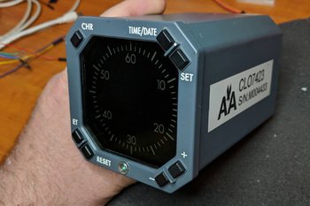
/The bezels that have replaced the acrylic bezels made by FDS. The landing gear, clock annunciators (korrys) and brake pressure gauge are OEM parts converted for flight simulator use - First Officer side. Note OEM Korrys and clock
I recently upgraded the display unit bezels (frames) on the Main Instrument Panel (MIP).
The previous bezels, manufactured by Flight Deck Solutions (FDS), lacked the detail I was wanting. Increasingly, I found myself being fixated by glaringly incorrect hallmarks that did not conform to the original equipment manufacturer (OEM) – in particular, the use of incorrectly positioned attachment screws, the lack of a well-defined hinge mechanism, and the use of acrylic rather than aluminum.
Although it is not necessary to have replicated items that conform to a real part, it does add to the immersion level, especially if you are using predominately OEM parts. The MIP in my case is a skeleton on which to hang the various real aircraft parts that have been converted for flight simulator use.
This is not a review, but more a reason to why sometimes there is a need to change from one product to another.
The OEM display is a solid unit that incorporates the avionics, display and bezel in the one unit. This unit has the protective plastic attached to the screen
OEM Display Units
The OEM display units used in the Boeing Next Generation airframes comprise a large rectangular box that houses the necessary avionics and glass screen for the display.
The display unit is mounted by sliding the box into the MIP along two purpose-built sliding rails. The unit is then locked into the MIP by closing the hinge lever and tightening the thumb screw on the lower right hand side of the bezel. The hinge mechanism is unique to the OEM unit in that once the thumb screw is loosened; one side of the lower display adjacent to the hinge becomes a lever in which to pull the unit free of its locking points in the MIP. The units are usually manufactured by Honeywell. Because the display unit is one piece, which incorporates the bezel as part of the assembly, it is not possible to obtain just the bezel – this is why a reproduction bezel is necessary.
Display Glass
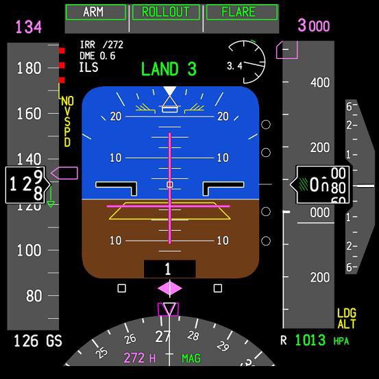
The front glass primary flight displays are clear/neutral density with anti-reflective coatings. They do not have a distinct colour, but rather appear grey or black when powered off. They are high-resolution LCD (Liquid Crystal Display) screens. This is why the reproductions often use tinted acrylic (smoke or grey in tint) - it stops you seeing the computer monitor’s LCD screen. For this to occur you need quite a high level of tint.
Once the brightness level on the monitor is increased and the contrast tweaked you barely notice the difference.
Reproduction Bezels
Reproduction bezels are manufactured by several companies – Open Cockpits, SimWorld, Fly Engravity and Flight Deck Solutions to name a few. As with all replica parts, each company makes their products to differing levels of accuracy, detail and quality.
I looked at several companies. The closest to OEM were the bezels manufactured by Fly Engravity and CP Flight (CP Flight are a reseller of Fly Engravity products).
The main reasons for changing-out the FDS bezels were as follows:
FDS bezels have two Philips head screws in the upper left and right hand side of the bezel. These are used to attach the bezel to the MIP. The real bezel does not have these screws.
FDS bezels are made from acrylic. The bezels in the real B737, although part of a larger unit, are made from aluminium. Fly Engravity make their bezels from aluminium which are professionally painted with the correct Boeing grey.
FDS have not replicated the hinge in the lower section of the bezel. Rather, they have lightly engraved into the acrylic a facsimile of the hinge. Fly Engravity fabricate a hinge mechanism, and although it does not function (there is absolutely no need for it to function) it replicates the appearance of the real hinge.
FDS use 1mm thick clear Perspex whereby the real aircraft uses smoke grey-tinted glass. Fly Engravity bezels use 3 mm smoke grey-tinted Perspex.
The Perspex used by FDS is very thin and is attached to the inside of the bezel by double-side tape. The thinness of the material means that when cleaning the display it is quite easy to push the material inwards which in turn breaks the sticky seal between the Perspex and the inside of the bezel. Fly Engravity use thicker Perspex that is attached to the inside of the bezel by four screws. It is very solid and will not come loose. Furthermore, the perspex used by FDS is clear, while that used by Fly Engravity is tinted.
Concerning the tint. Because the tint is quite dark, the brightness level on the monitor must be increased and the contrast tweaked to enable the PFD’s display to be clearly seen.
Table 1: Quick reference to the assailant points.
Detail showing the hinge mechanism in the Fly Engravity bezel. Although the hinge is non-functional, the detail and depth of the cut in the aluminium frame provides the illusion of a functioning hinge mechanism
Attaching the Bezels to the FDS MIP
The FDS and Fly Engravity bezels are identical in size; therefore, there is not an issue with the alignment of the bezels with MIP – they fit perfectly.
Attaching the Fly Engravity bezels to the FDS MIP is not difficult. The Fly Engravity bezels are secured to the MIP using the same holes in the MIP that were used to secure the FDS bezels. However, the screws used by Fly Engravity are a larger diameter; therefore, you will have to enlarge the holes in the MIP skeleton.
Detail of the hinge thumb knob on the Fly Engravity bezel. Although the internal screw is missing from the knob, the cross-hatched pattern on the knob compensates. The knob is screwed directly into the aluminium frame and can be loosened or tightened as desired. The circular device is a facsimile of the ambient light sensor
For the most part the holes align correctly, although with my set-up I had to drill two new holes in the MIP.
The Fly Engravity bezels, unlike the FDS bezels, are secured from the rear of the bezel via the backside of the MIP. The bezel and Perspex have precut and threaded holes for easy installation of the thumb screws.
Cross section of the Fly Engravity bezel showing the detail of the Perspex and attachment screw
Upgrade Benefits - Advantages and Disadvantages
If you are wishing to replicate the real 737 MIP as much as possible, then the benefits of upgrading to a Fly Engravity bezel are obvious. However, the downside is that the aluminium bezels, in comparison to acrylic-made bezels are not inexpensive.
The smoke grey-tinted Perspex has definite advantages in that the computer monitor screens that simulate the PFD, ND and EICAS appear a lot sharper and easier to see. But a disadvantage is that the computer monitors colour calibration alters a tad when using the tinted Perplex. This is easily rectified by calibrating your monitors to the correct colour gamut. I was concerned about glare and reflections, however, there is no more using the tinted Perspex than there is using the clear Perspex or no perspex.
The Fly Engravity bezels have one minor inaccuracy in that the small screw located in the middle of the hinge thumb knob is not simulated. This is a small oversight, which can be remedied by having a screw fitted to the knob.
Improvements
A possible improvement to the Fly Engravity bezels could be to use flat-headed screws, or to design a recessed head area into the rear of the Perspex (see above photograph which shows the height of the screw-head). A recessed area would allow the screw head to sit flush enabling the monitor screen to be flush with the rear of the Perspex.
The inability of the monitor screen to sit flush with the Perspex does not present a problem, but it is good engineering for items to fit correctly. If this is of concern, the screws can be discarded and either double-sided tape or glue used to secure the perspex to the inner side of the bezel.
Final Call
Although the bezels made by FDS do not replicate the OEM item, they are still of good quality and are functional. However, if you are seeking authenticity and prefer an aluminium bezel then those produced by Fly Engravity are superior.
Endorsement and Transparency
I have not been paid by Fly Engravity or any other reseller to write this post. The review is not endorsed and I paid full price for the products discussed.
Glossary
EICAS – Engine Indicator Crew Alert system.
MIP – Main Instrument Panel.
ND – Navigation Display.
OEM – Original Equipment Manufacturer (aka real aircraft part).
Perspex - Poly(methyl methacrylate), also known as acrylic or acrylic glass as well as by the trade names: Plexiglas, Acrylic, Lucite, and Perspex among several others.
PFD – Primary Flight Display.