B737 Throttle Quadrant - Automated Thrust Lever Movement

Autothrottle arming switch is a solenoid operated switch clearly identified on the main Instrument Panel (MCP).  The switch is linked to the IAS/MACH speed window (adjacent) and to two A/T disconnect buttons located either side of the throttle lever handles. cp flight pro mcp

In this final post dealing with the conversion of the 737-500 throttle quadrant. I will discuss the automation and movement of the throttle thrust levers and touch on some problems that occurred.  I will also briefly discuss the installation and use of potentiometers.  Part of this post will be repetitive as I briefly discussed automation in an earlier post.

Avoiding Confusion - Automation

To avoid confusion, automation refers only to the movement of the two throttle thrust levers in relation to the %N1 output.  These N1 limits and targets are provided by the Flight Management Computer (FMC) and normally are used by the Autopilot Flight Director System (AFDS) and the Auto Throttle (A/T) to maintain airspeed and/or thrust setting.  

Automation and Movement - Interface Cards

Automation is the use of CMD A or CMD B (autopilot) to control the %N1 outputs from the Autothrottle (logic), and motorization is the moving of the throttle levers in unison with %N1 output.  To achieve this seamlessly, two interface and one controller card are used.

Alpha Quadrant Cards (2):  Each  motor controller card has the automation logic programmed directly to the card (via propriety software).  One card controls Auto Pilot CMD A while the other card controls Autopilot CMD B.

Phidget Advanced Servo Card (2):  This card acts as an interface and bridge between the Alpha Quadrant cards and the flight simulator platform used.

The card does not provide movement for the throttle thrust levers; this is controlled by a Phidget Motor Controller card.

Leo Bodnar BUO 836 A Joystick Controller Card:  This card will register in Windows the movement of levers, buttons and switches on the TQ.  Calibration of this card is done first in Windows, then in Flight Simulator (FSX/P3D), FSUIPC or the avionics suite used; for example, ProSim737.

The interface cards are mounted forward of the MIP within the Throttle Interface Module (TIM) and are connected to the throttle unit by custom VGA straight-through cables and to the computer by a single USB cable.

Main Controller Cards

The controller card I have used is not a Phidget card but a specialist card often used in robotics (Alpha Quadrant card).  The software to program the card has been independently developed by a software engineer and does not utilize Phidgets.

The technology used in the controller card is very similar to that utilized by NASA to control their robotic landers used in the space industry.  The technology is also used to control robots used in the car industry and in other mass production streams.  One of the benefits of the card is that it utilizes a software chip (firmware) that can be easily upgraded, reprogrammed, or replaced.  

The Alpha Quadrant cards provide the logic to operate the throttle automation (the movement of the thrust levers) and act as a bridge between the two cards and the avionics suite.

Being able to program each card allows replication of real aircraft logic and systems.  Whenever possible, these systems and their logic have been faithfully reproduced.

oem throttle. toga switches clearly seen

CMD A/B Autopilot - Two Independent Systems

Most throttle units only use one motor controller card which controls either CMD A or CMD B; whichever autopilot you select is controlled by the same card.  

In the real aircraft to provide for redundancy, each auto pilot system is separate.  This redundancy has been duplicated by using two Alpha Quadrant controller cards, rather than a single card.  Each controller card has been independently programmed and wired to operate on a separate system.  Therefore, although only one CMD is operational at any one time, a completely separate second system is available if CMD A or B is selected on the MCP.

Synchronized or Independent Lever Motorization

Synchronization refers to whether the two throttle thrust levers, based upon separate engine %N1 outputs, move in unison with each other (together) or move independently.

In earlier Boeing aircraft, such as the 707, 727 and 737 classics, the levers were roughly synchronized; however, the Next Generation has as a computer-operated fuel control system which can minutely adjust the %N1 of each engine.  This advanced fuel management can be observed in a real aircraft whereby each throttle lever creeps forward or aft independent of the other lever.

Programming flight simulator to read separate %N1 outputs for each engine, and then extrapolating the data to allow two motors to move the throttle levers independently is possible; however, the outputs are often inaccurate (for varying reasons).  This inaccuracy can often be observed on reproduction throttle units that exhibit a gap between lever one and lever two when automating %N1 outputs.  

It was decided to maintain the older system and have both levers synchronized.  Although this is not replicating the Next Generation system, it does make calibration easier.  If in the future incremental thrust lever movement is required, it’s a matter of adding another 12 Volt motor to the front of the throttle bulkhead to power the second thrust lever.  

Autothrottle activation will advance both thrust levers in unison to the fmc calculated %N1 output

Be aware that although both thrust levers are synchronized, the throttle handles may still show a slight difference in position in relation to each other.  This is caused by the varying tension that needs to be maintained on the fan belt connecting the 12 Volt motor to the mechanical system beneath the thrust levers.

Another aspect to note is that the position of the thrust levers during automation is arbitrary and is a visual representation of the %N1 output; it may or may not reflect the exact position on the throttle arc that the thrust lever would be placed if moved manually (by hand with Autothrottle turned off).  

Although the throttle is automated, manual override (moving the thrust levers by hand) is possible at any time, provided the override is within the constraints of the aircraft logic (programmed into the Alpha Quadrant card), and that provided by the flight avionics (ProSim737).  

Power Requirements and Mechanics

To provide the power to move the throttle thrust levers, a 12 Volt motor previously used to power electric automobile windows, is mounted forward of the throttle bulkhead (see image at bottom of post).  Connected to the motor's pulley is a fan belt that connects to the main pulley located beneath the thrust levers.  To enable the thrust levers to move in unison, a slip clutch, which is part of the main pulley assembly, is used.  

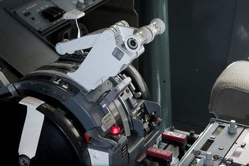
Captain-side TO/GA button is clearly seen below lever handles.  The button at the end of the handle is the Autothrottle disconnect button

ProSim737 Limitations - TO/GA and Auto Throttle Override

Unfortunately, concerning automation the ProSim737 is deficient in two areas: TO/GA and A/T Override.

(A)  TO/GA

In the real aircraft, the flight crew advances the thrust levers to power 40%N1 (or to whatever the airline policy dictates), allows the engines to spool, and then pushes the TO/GA button/s.  Pressing TO/GA causes the throttle to go on-line and to be controlled by the AFDS logic.  The throttle levers then advance automatically to whatever %N1 the logic deems appropriate based on takeoff calculations.

As at the time of writing. If you're using ProSim737, this will NOT occur.  Rather, you will observe the thrust levers retard before they advance (assuming you have moved the thrust levers to %40 N1).  The reason for this is nothing to do with how the throttle is calibrated, FSUIPC or anything else.  ProSim737 software controls the %N1 outputs for the automation of the thrust levers and the developer of the software has not fine-tuned the calibration in the software to take into account real-world avionics logic.  This thread located on the ProSim737 forum provides additional information. 

I have not tested Sim Avionics, but have been told this issue doesn't occur in their avionics suite.

There are two workarounds:  Engage TO/GA from idle (hardly realistic) or push the thrust levers to around 80% N1, allow the engines to spool, then push TO/GA.  Anything less that around 80% N1 will cause the thrust levers to retard before advancing.

Latest ProSim737 release (V133)

The latest version of ProSim737 (V-133) has provided improvement to the above issue.  Throttles can now be advanced to ~60% N1 and TOGA engaged without the throttle levers retarding.  This is possible ONLY if you calibrate the throttle levers within ProSim and allow ProSim to control the throttle output logic.  if you calibrate within FSUIPC then the same issue will apply.

According to ProSim developers, this issue is probably related to the calibration of the ProSim servo output. When you press TO/GA, the current N1 is taken and calculated back to a throttle percentage. This throttle percentage, when combined with the servo calibration data from ProSim results in a servo output. The servo calibration at the moment only has 2 calibration points, which are 0 and 100%. This results in a linear behavior between the two points, while depending on the construction of the throttle, the relationship might be non-linear. This would require a multi point calibration which is hard to do at the moment, because a throttle does not have exact readouts of the current position, so it will be hard to calibrate a 50% point.

This may need improvement in the code to auto calibrate the throttle system.

It's hoped that future release of ProSim737 will rectify this issue.

(B) Autothrottle Manual Override

In the real aircraft, manual override is available to a flight crew and the thrust levers can be retarded with the Autothrottle engaged.  When the flight crew release pressure on the thrust levers the Autothrottle will take control again and return the thrust levers to the appropriate position on the throttle arc dependent upon the speed indicated in the speed window of the MCP.

ProSim737 will not temporarily disconnect (manual override) the Autothrottle.  

At the time of writing, there is no workaround to solve this.

Potentiometers

There are many types of potentiometers; the two types most commonly used in flight simulation are the linear and rotary types. Linear potentiometers are inexpensive, often have a +- percentage variance, are compact, have a minimal throw depending upon the size of the device, and are not immune to contaminates building up on their carbon track. 

The last point is worth mentioning, as it is wrongly assumed that a potentiometer will remain correctly calibrated for the life of the unit.  General wear and tear, dust, and other debris will accumulate on the potentiometer; any of which may cause calibration and accuracy problems.  Keeping the potentiometers free of dust is important.

Rotary potentiometers (which may have a string attached) are very accurate, are in a sealed case and have very minimum chance of contamination. They are also made too exacting standards, are larger in size, and are expensive.

To read further about potentiometers

QAMP secured to base of throttle unit.  Thumb screws are visible on each corner of the plate.  A possible add on modification to reduce the risk of dust contamination to the potentiometers is a plastic cover that fits over the plate (a lunch box)

Calibration of Potentiometers

The main method of calibrating the position of the thrust levers is by calibrating the potentiometer in Windows, then in FSX followed by fine tuning in FSUIPC (if needed).  

At the moment I am using linear potentiometers; therefore, at some stage cleaning or replacement may be required.   The 737 throttle quadrant is not cavernous and only certain sized potentiometers will fit into the unit; this combined with other parts and wiring means that the potentiometers are often inaccessible without removing other components.  

To allow speedier access to the potentiometers, a Quick Assess Mounting Plate was designed.

quick access mounting plate (QAMP). four linear potentiometers are mounted to the plate. Two grub screws secure the plate to the throttle chassis

Quick Access Mounting Plate (QAMP)

The potentiometers are mounted directly onto a custom-made aluminum plate that is attached to the inside of the throttle unit by solid thumb screws.   To access the plate, the side inspection cover of the throttle is removed (a few screws) followed by turning the thumb screws on the access plate.  This releases the plate.

A similar plate has been designed and constructed for use with the stand-by potentiometer that controls the flaps.  A more detailed picture of the QAMP can be seen here..

Below is a video showing the movement of the thrust levers with the autothrottle engaged recorded during a test flight. 


Teething Issues with the Throttle Conversion

It was envisaged that more problems would have surfaced than have occurred.  The major issues are outlined below:

(A) Trim Wheels

An early problem encountered was that the trim wheels when engaging generated considerable noise.  After checking through the system, it was discovered that the two-speed rotation of the trim wheels were causing the two nuts that hold each of the trim wheels in place to become loose.  This in turn caused the trim wheels to wobble  slightly generating undue noise.  

Solution:

Tighten the two nuts at the end of the rod that holds the two trim wheels in place.

(B) Flaps 5 Not Engaging

The problem with the flaps 5 micro-button has been discussed in an earlier post.  To summarize, when you moved the flaps lever to flaps 5 the correct flaps were not selected on the aircraft or registered on the PoKeys 55 interface card.  Several hours were spent checking connections, micro-buttons, wiring and the custom VGA cables that connect the flaps section of the quadrant to the appropiate interface module; the problem could not be discovered.  

Solution:

One of the two Belkin powered hubs located within the IMM had been replaced with another powered unit.  It appears the problem was that the replacement hub had too low a voltage, as a replacement with a higher voltage solved the problem.

(C) Throttle Thrust Levers Not Synchronizing (A/T on)

The two thrust levers of the quadrant did not synchronize when the Auto Throttle (A/T) was engaged; one lever would always be ahead or behind of the other.  At other times they would split apart (do the splits) when A/T was engaged.  

Solution:

The problem was easily solved by altering the tension on the slip clutch nut.  When the nut was  tightened, both levers moved together as one unit.  The secret was finding the appropriate torque.

(D) Throttle Thrust Levers Difficult To Move in Manual Mode (A/T Off)

The ability to move the thrust levers in manual mode (Autothrottle turned off) was not fluid and the levers occasionally snagged or were sticky when trying to move them.  

The fan belt is barely visible linking the pulley of the motor to the main pulley inside the quadrant

This is caused by the fan belt not moving smoothly through the groove of the pulley wheel.   The Autothrottle when engaged overrides any stickiness due to the power and torque of the Auto Throttle motor.

Solution:

Unfortunately, there isn’t a lot you can do to rectify this issue as it’s a by-product of using a mechanical system in which the fan belt is central to the consistent operation of the unit.  

The conundrum is that if you tighten the fan belt too much you will be unable to manually move the thrust levers as they will be exceptionally stiff and difficult to move (as you are pushing against the tension of the fan belt); however, if you loosen the fan belt too much, although the levers will move fluidly by hand, the fan belt may not have enough tension to move the levers when Auto throttle is engaged.  It’s a matter of compromise; selecting an appropriate in-between tension to allow acceptable manual and Autothrottle operation.

A more reliable method is to use a small gearbox, a simple slip clutch and a coupler to connect to the spur gear.  Another option is to use an electrical system.

Further thought needs to be done in this area before a decision is made to replace the fan belt system.  If a new system is incorporated, the change-out will be documented in a future post.

Conclusion

Despite some of the shortcomings to this conversion, in particular the mechanical fan belt system, the throttle unit shows a marked improvement on the earlier 300 series conversion. 

Since the project began there has been three throttle conversions, and wth each conversion has built upon knowledge learnt from earlier conversions.  Initially there was the 737-300 conversion in 2012, which was converted in a rudimentary way and only operated in manual mode.  This was followed by the conversion of the 737-500 throttle in 2016.  This throttle was then rebuilt and upgraded in 2017.

Further Information

  • A summary of the articles that address the conversion of the 737-500 series throttle quadrant conversion, and the rebuild and update can be found in Flight Controls/Throttle Quadrant.

Acronyms and Glossary

  • AFDS - Autopilot Flight Director system

  • A/T – Autothrottle

  • CMD A/B - Autopilot on/off for system A or system B

  • Flight Avionics Software - Sim Avionics, ProSim737 or similar

  • FMC - Flight Management Computer

  • MCP - Main Control Panel

  • QAMP – Quick Access Mounting Plate

  • Throttle Arc – The arc of the thrust levers from the end of the blocks to fully forward.  The term refers to the curved piece of aluminum that the throttle levers are moved along

  • TO/GA - Takeoff Go-around switch

  • %N1 -  Very simply explained, %N1 is throttle demand and as N1 (and N2) spin at absurdly high speeds, it is easier to simply reference a percentage and display that to the crew. It's much easier for our brains to interpret a value on a scale of 0-100% rather than tens of thousands of RPM 

Adding A New Forward Section To The Existing Platform

nicolson rotary router

After spending time working with some minor, but frustratingly time consuming 'teething problems' with the throttle quadrant, I decided it was time to do something different.  Therefore, I have added a meter or so to the front of the platform.  The reason for the addition was to make an area on the platform for the computers and power supplies to reside, rather than just sit on the floor of the room.

Addition From Wood - Not Aluminum

To use aluminium for the forward addition is a  waste of material and resources.  After all, the forward section of the platform is located behind the Main Instrument Panel (MIP) and is not readily visible.  I have used wood obtained from the local recycling center - I enjoy recycling products as much as possible... 

The platform I am using is modular, and it's comparatively easy to add sections to increase its overall size.

In the photograph above, a Nicolson router is being used  to make the circular holes that will be used to route the cables from the throttle quadrant to the Interface Master Module (IMM) and computer.   .

Nicolson Tools (USA)

Nicolson tools are made in the USA and the company produces very heavy and beefy products; the very sharp router made short work of the 2 cm thick wood

The forward platform addition will fit snugly against the existing aluminium platform and blend almost seamlessly.

Other articles dealing with the floor structure can be read below.

B737 Throttle Quadrant - Parking Brake Mechanism

oem 737-500 parking brake lever and light

This post we will briefly discuss the conversion of the parking brake mechanism, and a video will demonstrate the solenoid engaging to move the lever within the mechanism.   The function of the parking brake is self-explanatory.

Parking Brake - Solenoid Auto Release

The parking brake can be engaged or disengaged by either engaging (lifting) or disengaging (pushing down) the park lever, or by depressing the toe brakes located on the rudder pedals. 

In the real aircraft, mechanical linkages and a cam disengage the parking brake.  A solenoid has been installed to replicate this in the simulator.

Interfacing with Flight Simulator

To use the solenoid, a relay card (on/off) and standard toggle-style switch is used.  The relay card is mounted in the Trial Interface Master Module (IMM) and connection from the throttle to the IMM is via a straight-through custom VGA cable. Any brand relay card will do this job.

Red Bulb

The red light is illuminated by a 28 Volt bayonet-style light bulb.  The bulb can be downgraded to 12 Volts; however, the illumination produced will not be as bright as if a 28 volt bulb was used. 

Spring, Solenoid and Toggle

The operation of the park brake lever revolves around four items:

  1. A long rod that connects from the lower section of the park lever to the toggle switch;

  2. A standard on/off toggle-style switch;

  3. A solenoid;

  4. A high tensile spring; and,

  5. A relay card.

parking brake Solenoid attached to port side firewall of throttle unit

When the park brake lever is pushed down or pulled up a corresponding movement of the long rod occurs.  Connected to the lower part of the rod is a standard-style toggle switch and a spring.  The spring is attached to the base of the throttle unit.  Movement of the rod causes the toggle to either be switched on or off (up/down), while the spring provides the tension for the automatic movement of the park lever to occur when the solenoid is energized (the lever is pulled downwards to the disengaged position).  A relay card is connected to the solenoid to control the timing that the solenoid receives power.

Toe Brakes Activation of Park Brake

As in the real aircraft, the parking brake can be released by the pilot depressing the toe brakes. 

There are  two methods commonly used to connect the toe brakes to the release of the park brake lever and parking brakes.  

The first (and easiest) method uses a Phidget 0/0/4 (1014_1) relay card and logic from within FSX or the avionics software (ProSim737), while the second method is a standalone closed system that can be implemented using a double-throw relay and a momentary switch; the switch being specific to the park brake.  For simplicity, I have incorporated the first method into the simulator as ProSim737 and FSX already provide a software solution to release the parking brakes.

Below is a short video showing how the parking brake mechanism operates.


737 throttle parking brake mechanism


In the next and final post regarding the throttle conversion, we will inspect the movement of the thrust levers during engagement of the Autothrottle (A/T) and discuss some of the teething issues with the throttle conversion.

Update

on 2017-06-26 06:40 by FLAPS 2 APPROACH

In June 2015, this mechanism was replaced with a more reliable system that replicates how the system operates in the real Boeing aircraft.  The system now in place is purely mechanical and does not rely on ProSim-AR for operation (other than registration of the movement of the parking brake lever).

B737 Throttle Quadrant - Trim Wheels and Trim Indicator Tabs

Captain-side trim wheel and trim tab indicator.  I was fortunate that the throttle unit I aquired retained its light plates in excellent condition.  It's not uncommon to find that the light plates are faded, scratched and cracked from removal of the unit from the aircraft

This post, the third last concerning the throttle quadrant conversion, will discuss the spinning of the trim wheels and movement of the trim tab indicators; both integral components of the throttle quadrant.  For a list of articles about the conversion of the throttle quadrant, see the bottom of this page.

1:  TRIM WHEELS

The trim wheels were implemented by Boeing in the mid 1950’s with the introduction of the Boeing 707 aircraft and been a part of the flight deck ever since.  The main reason Boeing has continued the use of this system in contrast with other manufacturer, who have removed the spinning trim wheels is redundancy.  Boeing believes that the flight crew should have the ability to manually alter trim should a number of cascading failures occur.

Whatever the reason for Boeing continuing with this older style technology, many flight crews have learnt to “hate “ the spinning trim wheels.  They are noisy and distracting, not to mention dangerous if a flight crew accidentally leaves the handle in the extended position; there is a reason that they are called “knee knockers”.  

Many virtual pilots are accustomed to using manual trim when flying a Cessna or a small twin such as the King Air.  In such aircraft altering trim by hand is straightforward and a necessary part of trimming the aircraft.  However, a jet such as the B737 it is a tad different; to alter the trim by hand would require the flight crew to manually rotate the trim wheels several dozen times to notice any appreciable result in trim.  As such, the electric trim switches on the yokes are mainly used to alter trim.

Motors, Interface Cards and Speed of Trim Wheel

The power to spin the trim wheels comes from two 12 Volt DC pump motors installed within the throttle unit.  A Phidget High Current AC Controller card is used to interface the trim wheels to the flight avionics software (proSim737). The cards are located in the Interface Master Module (IMM) and connected to the throttle unit by customised VGA cables.

The trim wheels can spin at two speeds.  The autopilot producing a different speed to that of manual trim (no automation selected).  A Phidget card is used to control the variability, with each of the two channels programmed to a different speed.  To alter the actual revolutions of the trim wheel, each channel is accessible directly from within the ProSim737 software configuration.   

To allow the trim system to be used by CMD A and/or CMD B, a second card is installed to ensure duplicity.  

Correct Timing

The trim wheels have white longitudinal line painted on each trim wheel.  This line serves two purposes: as a visual reference when the trims wheels are spinning, and to determine the number of revolutions per second during calibration.  To ascertain the correct number of wheel revolutions per second, a digital tachometer is used in the same way a mechanic would tune an older style motor vehicle.

Out of interest, in manual trim, 250 revolutions of the trim wheels are necessary to move the trim tab indicators from full up to full down.

Two Speed or Four ?

The B737 has four different trim revolution speeds, each speed dependent upon the level of automation used and the radio altitude the aircraft is above the ground.

Although it is possible to program this logic into the Alpha Quadrant cards and bypass ProSim737 software entirely (closed system), it was decided not to as the difference in two of the four speeds is marginal and probably unnoticeable.  Further, the level of complexity increases somewhat programming four speeds. 

Autopilot mode rotates the trim wheels at a faster rate than when in manual trim.

Trim wheel removed showing heavy duty spline shaft

Trim Wheel Braking

The real 737 incorporates a braking mechanism on the trim wheels that inhibits wheel movement when there is no input received to the system from either the auto pilot or electric trim switches. The brake operates by electromagnetic radiation and is always on, being released when an input is received.  

An unsuccessful attempt was made to replicate this using two military specification high torque brake motors.   The motors incorporate a brake mechanism, but the torque was so high and the breaking potential so great, that when the brake was reengaging/disengaging there was a loud thud that could not be ignored.  Further, the motor became very hot when the brake system was engaged and vibrated excessively due to its high power rating.

At the time, a lower torque motor could not be procured and a decision was made to use the 12 volt pump motors.  Therefore; the trim wheels take an extra second or so to spin down – not a major imposition and barely noticeable when flying the aircraft..

Deactivating Trim Wheel Spinning

Most of my virtual flying is at night and noisy and vibrating trim wheels can easily aggravate others in the house attempting to sleep.  To allow easy disconnection of the trim wheels, I have configured the right side trim stabilizer toggle to cut the power to the trim wheels.  Although not authentic, sometimes minor alterations need to be made to a system to make it more user friendly.

2:  TRIM TAB INDICATOR MOVEMENT

The trim tab indicators are used as a visual reference to indicate to the flight crew the trim of the aircraft.  The trim and subsequent movement of the indicator tabs are activated either by depressing the electric trim switch on the yoke or by turning the trim wheels by hand.

Phidget Card

A Phidget Motor Controller Advanced Servo card and servo is used to control the movement of the two trim tab indicators, while the logic to activate the servo is directly from the flight avionics software.  The speed that the trim tabs move is set through ProSim737 (trim speed).

Aluminum tab connected to servo.  Servo is mounted behind aluminium plate.  You can just make out the screw wire between the servo and the tab

Hardware Modifications

To allow the servo to connect directly to the trim tab indicators, a small tab of aluminium was welded to the main trim tab shaft.  A thin screw wire was then connected from the servo to the tab to allow nay movement of the trim tab to be registered by the servo. 

Determining Accuracy

There is little point in implementing movement of the trim tab indicators if a high level of accuracy is not possible; therefore, it’s important that that the position of the tabs matches that of the flight avionics software and virtual aircraft.  To ensure positional accuracy and maintain repeatability the servo was calibrated throughout its range of movement and checked against the “virtual trim tab strip” that can be placed on the EICAS screen within the ProSim737 software.  

The short video below shows the smoothness in movement of the trim tab indicators.  You will note the TQ vibrates somewhat.  This is because I have yet to secure it to the platform.


B737 Throttle Quadrant - Flaps UP to 40; Conversion and Use

This post examines the flaps lever on the refurbished B737 throttle and how it was converted to flight simulator use..

Flaps are used to slow the aircraft by creating drag, and to apply positive lift during takeoff.  The flaps lever is located on the First Officer’s side of the throttle quadrant. 

Subsequent movement of the flaps lever is indicated by illumination of the Le Flaps Transit and Le Flaps EXT lights located on the Main Instrument Panel (MIP), movement of a needle in the flaps gauge, a change of indication in the Primary Flight Display (PFD) and illumination of the Leading Edge Device (LED) panel located on the aft overhead panel. 

There are other less obvious indicators, but this is not the direction of his post.

The flaps lever is an integral part of the throttle unit.  Ensuring it operates correctly and with accuracy is important.

oem 737 throttle showing flaps arc and takeoff cg%mac

Safety Features

Newcomers to an OEM throttle quadrant are often surprised at how difficult it is to manipulate the flaps lever; it isn't a simple pull or push of a lever - there is a reason for this. 

When flaps are extended, especially at slow air speeds the flight dynamics of the aircraft are altered.  To protect against accidental flap extension, Boeing has designed the flaps lever so that a flight crew has to physically lift the lever before moving the lever to the required flap setting.  

Further safety has been designed into the system by having flaps 1 and flaps 15 guarded by a flaps gate.  The gate prevents straight-through movement of the flaps lever beyond flaps 1 and 15.  The  pilot must actually lift, push and drag the lever through the gate to the next setting.

It takes a short time to become accustomed to how to move the lever for smooth operation.

Traditional Approach used in Flaps Conversion

In most throttle conversions, a single potentiometer is used and the flaps are calibrated directly through FSUPIC.  A linear rod is attached to the potentiometer and then to the lower end of the flaps lever.  When the flaps lever is moved, the rod is moved forward or aft causing the potentiometer to turn to a defined and pre-calibrated position.  The analogue movement of the rod is converted to a digital signal that can be read by Flight Simulator.

In such a conversion, it’s important to ensure that the physical position of the flaps lever matches the flaps position used in Flight Simulator and in the flaps gauge.  It’s also vital that flaps are calibrated to ensure accurate operation.

The benefits of using this traditional method are that it’s “tried and true”, inexpensive and relatively easy to implement.  Calibration is the major key; however, using FSUIPC can be troublesome and time consuming, although once calibrated everything should operate reasonably well.  

Potentiometers - Accuracy and Longevity

Potentiometers came in a variety of sizes with differing throw values.  A throw is the length of movement that a potentiometer will allow a linear rod to move.  The larger the potentiometer the more throw allowed.  The potentiometer for the flaps must fit within the throttle unit beneath the flaps mechanism in a relatively small space.  Unfortunately, with Boeing 737 late model throttle’s there is minimal room to allow a larger than 60mm potentiometer to be installed.  Using a 60 mm potentiometer means that the device has a minimal throw.

This throw, if lucky, can be stretched to cater from flaps 0 to flaps 40, but only after facetiously calibrating with FSUPIC.  More often than not,  the throw will only reach flaps 1 or flaps 30.  Often this lack of throw goes unnoticed and many virtual pilots select flaps 40 believing they actually have flaps 40, but in reality it is flaps 30.

Longevity is another more minor issue when using potentiometers.  Most potentiometers have a +- tolerance during manufacture, are made cheaply and depending upon the type selected are open to contamination from dust and debris.  Dust on a potentimeter can affect the accurancy of the unit. At the very least, maintenance is required if the potentiometer is located in a dusty area.

Several Ways to Skin a Cat.....

To solve these potential problems two methods were assessed.  The first was using two micro- buttons at each end of the linear rod that connects the flaps lever with the potentiometer.  These buttons can be assigned directly with FSUPIC to flaps UP and flaps 40.  This theoretically would solve the shortness of throw experienced with traditional conversion and calibration.  Flaps UP and 40 are controlled by micro-buttons and everything in-between is calibrated within FSUPIC.

Working through an issue with the Flaps 5 micro button, custom VGA cable and PoKey card. it's not all fun.  Chasing problems can be frustrating and very time consuming

Micro-buttons

The second method is to replace the potentiometer with micro-buttons; thereby,  rectifying the issue of minimal throw.  Replacement will also alleviate the chance of a potentiometer being inaccurate, remove any chance of contamination, and also remove the tedious task of calibrating flaps in FSUIPC.   

The use of micro-buttons to control flaps movement is relatively novel, but the potential benefits of implementing this into the throttle unit could not be overlooked; therefore, it was decided to use this method.

Problems with Micro-buttons - Design of Lower Flaps Arc Plate (LFAP)

The first initial problem encountered is that micro-buttons are small, delicate and can be easily damaged if mounted directly onto the metal flaps arc.  Manipulating the flaps lever requires considerable pressure to pull, drag and drop the lever into the correct flaps detent position. Clearly, mounting the buttons on top of the metal flaps arc for direct contact with the flaps lever was not feasible.

After much thought, it was decided to fabricate from aluminum, a plate that replicated the arc that the flaps lever moves over.  This plate has been called the Lower Flaps Arc Plate (LFAP).  The micro-buttons were then strategically mounted to the plate, each buttons’ position corresponding to a flap position.  The LFAP with the mounted buttons was then mounted directly beneath the existing flap arc plate. 

Design Considerations

Before implementing a new design, considerable thought must be taken to potential problems that may arise from the design.  In the case of using micro-buttons the issue was connectivity and the possibility of a damaged or faulty button.  The LFAP can be accessed relatively easily by removing the First Officer's side panel which allows access to the plate from behind the trim wheel.

Half-moon Provides Accuracy, Reliability and Repeatability

To enable the micro-buttons to be triggered by the flaps lever, a half-moon piece of aluminum was fabricated using the same dimensions of the lower portion of the flaps lever.  One end of the "half-moon" was  curve-shaped pointing downwards. The "half-moon" was then screwed to the lower section of the flaps lever handle   

LEFT:  Rough initial sketch of half-moon showing relationship to flaps arc and micro-buttons.

When the flaps lever is dropped into a flaps detent position, the curved side touches and depresses the micro-button mounted on the lower flaps arc plate.  When the flaps lever is moved to another flaps setting, the lever is first lifted breaking contact with the button, moved to the next setting and dropped into the detent position triggering the next button and so forth.

Interface Card

A standard PoKeys 55 interface card was used to connect the outputs from the buttons to the avionics suite software.  ProSim737 software allows easy interfacing by allowing direct connection of a button to a specific flap position.  If ProSim737 is not used and the chosen avionics suite does not support direct connection, FSUIPC can be used to assign individual buttons to flap positions.  The PoKeys card is installed in the Interface Master Module (IMM).

Advantages of Micro-buttons - It's Worth The Effort...

The benefits of using micro-buttons cannot be underestimated. 

  • 100 % accuracy of flap movement from flaps UP to flaps 40 at all times.

  • No calibration required using FSUIPC.

  • Non-reliance on FSUIPC software as the installation is mechanical.

  • Very easy configuration of flaps UP through flaps 40 using ProSim737 software configuration.

  • Removal of the potentiometer and possible inaccuracy caused by +- variation.

  • No concern regarding possible contamination of the potentiometers.

  • Enhanced reliability of operation with no maintenance required.

  • Easy removal of the Lower Flaps Arc Plate to facilitate button replacement.

Back-up Potentiometer System

Although the use of micro-buttons is successful, I still have a potentiometer installed that can be used to operate the flaps.  The reason for installing the potentiometer was in case the micro-buttons did not work correctly; it would save time installing a replacement system.  To change from buttons to the potentiometer is as easy as disconnecting one quick release connector and reconnecting it to another.

qamp. the quick access mounting plate enablse 4 linear potentiometers to be mounted in one location. the qamp is located in throttle unit

Quick Access Mounting Plate (QAMP)

The potentiometer is mounted directly onto a custom-made aluminum plate that is attached to the inside of the throttle unit by solid thumb screws. 

The reason for the plate and screws was easy access should the potentiometer need to be cleaned or be replaced. 

To access the potentiometer requires the side inspection plate of the throttle be removed (a few screws) and then removal of the thumb screws on the access plate that allows the potentiometer to be dropped from its bracket.

Unfortunately, I failed to photograph the flaps QRMP before installation; however, its design is similar to all quick release plates used within the throttle unit.  The plates are made from aluminium and are attached to the throttle unit by thumb screws rather than nuts and bolts.  This allows for easier and faster change out if necessary.  The above image shows the QRMP for the throttle levers - the flaps QRMP is far smaller and thinner.

Troubleshooting

During testing a problem was observed with the micro-button for flaps 5.  For an unknown reason flaps 5 would not register correctly on the PoKeys 55 card.  After several hours troubleshooting the buttons and wiring, it was determined that the PoKeys card must have a damaged circuit or connection where they flaps 5 wire was installed to the card.

The problem turned out not to be the PoKeys card, but the Belkin USB hub installed to the Interface Master Module (IMM).  I had replaced the first hub (which I damaged) with another hub that had a lower voltage.  For some reason this lower voltage was not enough to allow operation of all the functions running from the hub. 

After replacing the hub with a higher voltage device, the issue with the flaps was immediately rectified.  Of course, this was after I spent literally hours troubleshooting flaps 5!  As stated earlier, teething issues on a new design can be frustratingly time consuming...

Video

I decided to make a short video that explains the button set-up a little better.  In the video you can clearly see the flaps arc, half-moon pencil and the micro-buttons.  The video is not the best quality as it was hand held in dim light after I removed the F/O side inspection plate of the throttle quadrant.  It's difficult if not impossible to setup a tripod in the flight deck once the throttle unit is bolted to the platform.


737 throttle flap arc buttons


Acronyms and Glossary

  • Flaps Arc – A curved piece of aluminum positioned directly beneath the flaps lever and corresponds to the curvature of the light plate.

  • Lower Flaps Arc Plate (LFAP) - A curved piece of aluminium that is the same size as the flaps arc and is mounted directly beneath the flaps arc.

  • Half-Moon Pencil – a custom fabricated piece of aluminum with a curved edge at one end.  Used to depress micro-buttons on flaps arc as flaps lever is moved..

  • OEM - Original Equipment Manufacturer.

  • Quick Access Mounting Plate QAMP – Quick Access Mounting Plate for the potentiometer that is a redundancy system for flaps movement.

  • Avionics Suite - Software that interacts with Flight Simulator to control avionics, gauges, etc - ProSim737, Sim Avionics, Project Magenta, etc.

Update

on 2014-02-12 02:13 by FLAPS 2 APPROACH

flaps half-moon

Several individuals have contacted me asking for a picture of the half moon, that is roughly sketched in the main post.  During a recent upgrade, the side panel and trim wheel were removed so I took the opportunity to take a photograph of the half-moon.

The half moon is secured to the lower section of the flaps lever by a screw, with the lower curved side facing downwards towards where the micro-buttons are positioned. The half-moon moves in unison with the flaps lever (when moved) and the curved section triggers micro-buttons as it passes over the button.  The micro-buttons are positioned at the correct position that relate to a specific flap detente.

Update

on 2019-09-09 07:29 by FLAPS 2 APPROACH

FLAPS OVERHAUL (LATE 2018/2019)

The mechanism used to convert the flaps on the throttle quadrant has been overhauled and replaced.  The method described in the above article worked well, however, a number of problems developed that were only noticeable after continual use.

B737 Aural Warning Module (AWM) Installed and Operational

front of oem aural warning module

One of the recent upgrades to the simulator has been the installation of an Aural Warning Module (AWM).  This module resides on the first officer side of the flight deck and is attached to the forward bulkhead of the Main Instrument Panel directly beside the throttle quadrant.  The module replaces four of the computer-synthesised warnings with the OEM counterparts.

The purpose of the module is straightforward; to provide a fail-safe mechanical device that delivers loud, clear and concise tones and bells to indicate to the flight crew that major problem or configuration issue exists.  The aural alarms activate in unison with warning lights that are located on the forward overhead panel, fire suppression panel and on the glare shield of the Main Instrument Panel (six pack annunciators and master fire warning (bell cutout) and master caution buttons).

What's in the Grey Box

The aural warning box contains three mechanical devices capable of delivering four aural warnings:

(i)    The fire bell;

(ii)   The clacker; and,

(iii)   The horn (double purpose that activates either in a continuous or intermittent tone).    

The fire bell rings when any number of events relating to a fire on the aircraft occurs.  The fire bell can be silenced by either pushing the master fire warning button located on the glare shield or bell cutout switch located on the fire suppression panel.  I will be discussing at length the fire suppression panel in a future post; therefore, will not discuss the various scenarios that the fire bell operates.

The overspeeed clacker sounds when the aircraft exceeds the maximum allowable airspeed (Vmo /Mno).  The warning clacker can only be silenced by reducing your airspeed below Vmo/Mno.

The intermittent horn is an aural cue for the takeoff configuration alert.  The horn will sound when a configuration problem exists with the aircraft.  For example, advancing the throttles with the parking break set or the flaps not set.  

When the horn is activated a takeoff config warning light (in red) illuminates on the left forward overhead panel.  Deactivation of the alarm is by retarding the throttle levers to idle and then configuring the aircraft correctly.

The continuous horn is activated when specific flight conditions are met. The following are the main scenarios that activate this alarm.

  • The aircraft is below 800 feet radio altitude with flaps set from UP to flaps 10 with either throttle thrust lever set between idle and 20 degrees forward of idle.

  • The aircraft descends below 200 feet radio altitude (any configuration)

  • The aircraft has flaps set 15 through 25 with either throttle thrust lever set between idle and 20 degrees forward of idle.

  • Flaps 15 is selected without the landing gear being in the down position.

  • The aircraft has flaps set greater than flaps 25.

  • The aircraft’s landing gear is not extended.

Silencing the Continuous Tone Horn

The horn can be silenced by depressing the horn cutout switch located on the throttle quadrant; however, if the aircraft descends below 200 feet radio altitude, or the flaps are extended greater than Flaps 15 (without landing gear extended), the horn cutout switch will not silence the horn.  

Lowering the landing gear or ascending to higher altitude will silence and reset the horn.

Inside the AWM: horn, clacker and bell.  The small box houses basic circuitry

OEM

The grey box is not an OEM part; however, is similar to the module used in the 800 series with the exception of a toggle switch located on the upper part of the unit (the toggle switch is used by maintenance).  The box was replicated (using vacuform technology) to the identical measurements of the OEM counterpart.  The replica box will be replaced when and if I find a 800 series OEM part.

The mechanical tones and bell have been acquired from a Boeing 737-200 series aircraft and retrofitted into the module. 

In time as OEM NG AWM will be procured.

Difference Between Classic Series and NG Aural Warning Modules

The AWM for the classic series (300, 400, 500) and NG are different.  The 500 is closest to the NG, however, was a transition product.

Earlier AWM were analogue and used circuits to generate (synthesize various sounds), such as chimes, navigation tunes, etc).  These AWM used mechanical devices to generate the mechanical sounds such as the horn and fire bell.

The NG AWM is 100% digital and has no physical mechanical devices to generate sound.  This said, apparently some earlier NG AWM still include the mechanical fire bell.

The 500 series AWM was transitional between analogue and digital.

The Next Generation AWM has a maintenance toggle at the upper part of the unit.  This can be used by maintenance to check the unit and to alter the volume.  However, it’s not possible to alter the volume of an individual sound – adjust one sound’s volume and they all either increase or decrease in volume relative to each other (this is what the engineer told me).  It’s not possible for pilot’s, using the toggle, to alter the volume or to select what sounds they hear.


Table 1:  Excerpt from Boeing maintenance manual explaining conditions necessary for operation


Conversion

The aural tones are mechanical and not software generated.  To interface the warnings with ProSim737 a Phidget 0/0/4 card has been used.  This card is located within the SIM interface module (SIM) and is connected to the aural warning module by a custom wired VGA cable.  The relays on the Phidget card are triggered when a specific condition, based on the offsets set within the avionics software, are met.

Authenticity and Volume

Although FSX, ProSim737, Sim Avionics and many other avionics suites include aural warnings within their package, the clarity and volume in sound produced by a mechanical device surpasses that of a computer generated sound.  

"A word of warning".  The horns and bell are loud – very loud… They are loud for a reason – to annoy a flight crew so that will not ignore the "urgency" of the alarm.  The first time the fire bell sounded during testing made me jump out of my skin!  It also activated the “yell” button on my wife…  

The devices do not have a volume control.  To quieten the aural warnings for “inside” simulation use, I’ve installed foam around the mechanical devices and bell.  This has been successful in lowering the volume by around 60%. 

Below is a short video showing the Aural Warning Module and its various sounds (turn volume up).


Boeing 737 OEM Steering Tiller Installed

oem 737-400 steering tiller mounted to bespoke aluminium plate

The steering tiller is an often overlooked piece of hardware for many virtual flyers.  The steering tiller provides greater control of the aircraft during taxi operations, and if calibrated correctly works very well.

OEM B737-400 Steering Tiller

The tiller has been salvaged from a 737-400 series aircraft and is identical to the tiller used in the Next Generation aircraft.  The actual OEM part is only the black handle and white arrow.  The remainder of the unit has been custom fabricated to allow easy attachment to the inside wall liners of the flight deck.

The simulator does not have a shell and liner at the moment; therefore, I've attached two pieces of grey-coloured wood to the unit to enable temporary installation to the forward left of the Captain's seat.  

A single potentiometer has been used allow calibration of the tiller mechanism.  A metal strip connects the potentiometer with a metal plate that connects to the the central area of the tiller mechanism.  As the steering tiller is turned left or right, the metal plate moves to and fro with a corresponding movement in the metal strip which registers on the potentiometer (see picture).

To create tension when the steering tiller is moved, several heavy duty springs have been used.  Although rudimentary in design, the tension of the springs provides a reasonable and constant pressure.  The springs also allow the handle to center itself easily when released.  Springs are renowned for creaking when they move and to remove this noise, heavy duty lithium grease has been applied to the upper parts of the spring heads where they join the metal. 

Tiller mechanism showing springs and potentiometer.  A linear potentiometer has been used in favour of a rotary potentiometer. Springs provide tension to center the tiller

Interface Card and Calibration

The tiller is connected directly to a Leo Bodnar BU086A interface card, although any joystick card such as a PoKeys card can be used.  A USB cable then runs from the interface card to the main computer.  To allow easy connection to the interface card (Leo Bodnar card) a female JR servo wire security clip has been used.  

The steering tiller requires careful calibration if it's to operate correctly.  Calibration is initially through Windows and then FSUIPC.  Using FSUIPC enables greater accuracy to be achieved.

The steering tiller, when calibrated through FSUIPC does not create an independent tiller axis but piggybacks on the movement of the rudder axis.  The developer has ingeniously written code that enables the tiller to be activated when groundspeed is under 60 kias.  Above this speed the rudder is activated.

How to Calibrate the Steering Tiller

  1. Connect the interface card to the computer via the USB cable.

  2. Using Windows, calibrate the axis of the interface card (if using Windows 7 type into the search bar joystick and select "Joystick Calibration").

  3. Following the on screen instructions, move the steering tiller handle forward and aft.  Then save the setting.

  4. Open Flight Simulator and then open “Settings/Control” in the FSX menu.

  5. Ensure that any joystick commands relating to the interface card are not registered by FSX.  If so, delete them and save.

  6. Open Flight Simulator and then open FSUIPC settings.

  7. Select the FSUIPC “Axis Assignment Tab”.  Then move the tiller handle to activate the calibration software.  (you will observe the numbers moving).

  8. Select from the left side of the screen the tab that says ”Type of Action Required”,  Select "Send Direct to FSUIPC Calibration".  Then open the menu box and scroll down to “Steering Tiller”.

  9. Open the “Joystick Calibration” tab in FSUIPC.  

  10. Scroll through the 11 entries searching for steering tiller (9/11).  When "Steering Tiller" is found, click the SET button which will open three (3) further buttons.  Each button refers to a position on the steering tiller axis.

  11. Turn the steering tiller to the left and click the RIGHT button.  Then turn the tiller to the right and select the LEFT button.  With the tiller in the central position click the MIDDLE button.  Oddly, on some setups the opposite is required.  If calibration fails, try again using the opposite direction.

  12. For more precise and accurate calibration, you may want to use the "Slope" and/or "Null Zone" functionality.

The steering tiller should now be calibrated and ready for use.

Troubleshooting and Suggestions

Some known problems that are easily solveable are:

A:  Only use the steering tiller at very low ground speeds.  If you turn the tiller to the full left or right and the speed is too great, the aircraft may remain stationary or slip; the reason being the nose wheel is locked at a right angle to the direction of travel.  I find the tiller works best turning the handle slowly.

B:  The direction of aircraft travel is opposite that of the tiller handle.  If this occurs, check your FSUIPC settings.  You may have to tick (check) the box that says REV.  REV reverses the direction of the axis (left to right and right to left).

C:  If the tiller exhibits sensitivity issues or if you require a dead zone, open FSUIPC and program the SLOPE function and/or set a NULL ZONE.

D:  If you have issues with the tiller not working correctly, do the calibration again in Windows and FSUIPC.  If calibrated correctly, the tiller will change to rudder control at 60 knots.

OEM is an acronym for Original Equipment Manufacturer.

B737 Throttle Quadrant - Speedbrake Conversion and Use

oem 737-500 throttle quarant speed brake lever

The speedbrake serves three purposes: to slow the aircraft in flight (by incurring drag), to slow the aircraft immediately upon landing, and to assist in the stopping of the aircraft during a Rejected Takeoff (RTO).  

There are four speedbrake settings: Down (detent), Armed, Flight Detent and Up. 

In addition, there are three speedbrake condition annunciators (lights), located on the Main Instrument Panel (MIP), that annunciate speedbrake protocol.  They are: Speedbrake Armed, Speedbrakes Do Not Arm and Speedbrakes Extended.  These annunciators (lights) illuminate when certain operating conditions are triggered.

This article is rather long as I've attempted to cover quite a bit of ground.  The first part of the post relates to technical aspects while the second portion deals with conversion.  Hopefully, the video at the end of this post will help to clarify what I have written.

Technical Information

Speedbrakes consist of flight spoilers and ground spoilers. The speedbrake lever controls a 'spoiler mixer', which positions the flight spoiler power control unit (PCU) and a ground spoiler control valve.   The surfaces are actuated by hydraulic power supplied to the power control units or to actuators on each surface.

Ground spoilers operate only on the ground, due to a ground spoiler shutoff valve which remains closed until the main gear strut compresses on touchdown (this is activated by the squat switch).

In Flight Operation

Actuation of the speedbrake lever causes all flight spoiler panels to rise symmetrically to act as speedbrakes.  The lever can be raised partly or fully to the UP position.  This causes the extension of the flight spoilers to the equivalent full up (ground spoiler) position.

Ground Operation

All flight and ground spoilers automatically rise to full extension on landing, if the speedbrake lever is in the ARMED position and both throttle thrust levers are in IDLE. When spin-up occurs on any two main wheels, the speedbrake lever moves to the UP position, and the spoilers extend.

When the right main landing gear shock strut is compressed, a mechanical linkage opens a hydraulic valve to extend the ground spoilers.  If a wheel spin-up signal is not detected, the speed brake lever moves to the UP position, and all spoiler panels deploy automatically after the ground safety sensor engages in the ground mode.

After touchdown, all spoiler panels retract automatically if either throttle thrust lever is advanced. The speedbrake lever will move to the DOWN detent.

All spoiler panels will extend automatically if takeoff is rejected (RTO) and either reverse thrust lever is positioned for reverse thrust. Wheel speed must be above 80 knots in order for the automatic extension of the spoilers to take place.

A failure in the automatic functions of the speedbrakes is indicated by the illumination of the SPEEDBRAKE DO NOT ARM Light. In the event the automatic system is inoperative, the speed brake lever must be selected manually placed in the UP position after landing by the pilot not flying.

Movement of Speedbrake Lever

The logic relating to the position of the speedbrake lever is:

DOWN (detent)

  • All flight and ground spoiler panels are in the closed position.

ARMED  

  • Automatic speedbrake system armed.

  • Upon touchdown and activation of the squat switch, the speedbrake lever moves to the UP position and all flight and ground spoilers are deployed.

FLIGHT DETENT

  • All flight spoilers are extended to their maximum position for inflight use.

UP

  • All flight and ground spoilers are extended to their maximum position for ground use.

Illumination of Speedbrake Condition Annunciators (korrys)

The logic relating to the illumination of the annunciator condition lights is:

Speedbrake Armed Annunciator

  • The light will not illuminate when the speedbrake lever is in the DOWN position.

  • The light illuminates green when the speedbrake is armed with valid automatic system inputs.

Speedbrake Do Not Arm Annunciator

  • The light will not illuminate when the speedbrake lever is in the DOWN position.

  • The light indicates AMBER if there is a problem (abnormal condition).

  • The light will illuminate during the landing roll following through 64 KIAS provided the speedbrake lever has not been stowed.  The light will extinguish when the aircraft stops or when the speedbrake lever is stowed.

Speedbrakes Extended Light

  • The annunciator illuminates AMBER pursuant to the following conditions.

In Flight

  • Amber light illuminates if speedbrake lever is positioned beyond the ARMED position, and

  • TE flaps are extended more than flaps 10, or

  • Aircraft has a radio altitude (RA) of less than 800 feet .

On The Ground

  • Amber light if the speedbrake is in the DOWN (detent) position.

  • Amber light if the ground spoilers are not stowed.

It is important to remember that the speedbrakes extended annunciator will not illuminate when the hydraulic systems A pressure is less than 750 psi.

Simulator Operation - What Works

  • Rejected Take Off (RTO) after 80 knots called - Activation of either reverse thrust lever and throttle to idle will extend spoilers (if RTO armed).  Lever moves to UP position on throttle quadrant.

  • Spoilers extend on landing when squat switch activated, throttles are at idle and lever is in armed position (3 requirements).  Lever moves to UP position on throttle quadrant automatically.

  • Spoilers extend automatically when reverse thrust is applied (if not previously armed - see above).

  • Engaging thrust after landing automatically closes spoilers.  Lever moves to DOWN position on throttle quadrant.

  • Speedbrakes extend incrementally in air dependent upon lever position (flight detente).

Speedbrake Logic - Alpha Quadrant Card and Closed-loop System

The logic for the speedbrake is identical to that found in the real Boeing aircraft and is 'hardwired' into the Alpha Quadrant card.  This card is located in the Interface Master Module (IMM) and is connected to the throttle quadrant by a custom-wired VGA cable.  Programming the Alpha Quadrant card is by stand-alone software.

The speedbrake system is a closed-loop system, meaning it does not require any interaction with the ProSim737; however, the illumination of the korry condition lights are not part of this system and therefore, require configuration in ProSim737  (a future update may include the condition korrys within the system). 

Conversion

A common method to convert the speedbrake is to use a potentiometer and then calibrate using FSUIPC (Flight Simulator Universal Inter-Process Communication).   Whilst this method is valid, it relies very much on FSUIPC to determine the accuracy of the visual position of the speedbrake lever.  The longevity of the system also very much depends upon the potentiometer used, its +- variance at time of manufacture and its cleanliness.  I wanted to move away from a potentiometer and FSUIPC and develop a more reliable and robust system.

Micro-buttons Replace Potentimeter

In the real Boeing 737 aircraft, a number of buttons reside beneath the arc that the speedbrake travels along.  As the speedbrake lever moves accross a button a condition is set.  If you slowly move the speedbrake level, and listen carefully, you can hear the switch activate as the lever moves over it.

This system has been replicated as closely as possible, by attaching a series of micro-buttons to a half-moon shaped arc made from aluminum.  The arc is installed directly beneath the speedbrake lever’s range of movement.  There are six micro-buttons installed and each button corresponds with the exact point that a function will be activated when the speedbrake lever moves over the button. 

The benefit of using buttons rather than a potentiometer is accuracy and reliability.  A button is on or off and there is little variance.  A potentiometer on the other hand has considerable variance in both accuracy and reliability.

In addition to the micro-buttons, there are two on/off buttons (read below) located on the forward bulkhead that control the arming of the speedbrake lever.

Relay Card

The micro-buttons are then connected to a Phidget 0/0/8 relay card (4 relays) that, depending upon the position of the speedbrake lever, turn on or off the programmed speedbrake logic.  The Phidget 0/0/8 relay card is located in the Interface Master Module (IMM). 

Basically, the system is a mechanical circuit controlled by micro switches that reads logic programmed into the Alpha Quadrant cards.  Because it’s a closed mechanical loop system, logic from the avionics suite (ProSim737) is not required.  Nor, is calibration by FSUPIC.

micro-button on speed brake lever

Arming the Speedbrake - The Detail

To arm the speedbrake, two micro-buttons, located forward of the throttle bulkhead and attached to a solid piece of metal are used.  Connecting the lower end of the speedbrake lever to the clutch assembly is a green coloured rod.  The rod is the linkage that moves the speedbrake lever.  Adjacent to this rod is a cylinder made from aluminum used to open or close the arming circuit.

As the speedbrake lever is brought into the arm position, the cylinder is moved until it touches either of the arming on/off button-switches.  

The cylinder will stay in the armed position until voltage is provided to the motor to move the speedbrake lever, which in turn moves the rod and cylinder. 

Power is sent to the motor in only two circumstances: when the aircraft lands and the squat switch is activated, or during a Rejected Takeoff (RTO).

The motor powering the movement of the lever is the angled motor. The two arming button switches can be seen, one is red the other black, while the rod, clutch assembly and cylinder can easily be identified.

motor and speed brake clutch assembly on forward part of throttle quadrant

Motor

Most enthusiasts use a servo motor to control the movement of the speedbrake lever.  I used a servo motor on my first TQ and was never satisfied at the speed the lever moved; it was always VERY slow and seemed to lack consistent power.

In this conversion a DC electric motor, previously used to automobile power electric windows was used.   The advantage in using a motor of this type is its small size, strong build quality and high torque output.  This translates to more than enough power to mobilize the speedbrake lever.  The motor is mounted to the front of the throttle bulkhead.

Clutch Assembly

The purpose of the clutch is to enable the movement of the motor’s internal shaft to be transferred to the rod which moves the speedbrake lever.  The clutch is fitted with a synthetic washer and a torque nut either loosens or tightens the clutch to either increase or decrease the drag pressure on the speedbrake lever (see photograph).  

Speedbrake Lever Movement - Variable Voltage to Control Speed

The speedbrake lever in the real B737 moves rather slowly when the lever is powered.  Traditionally, this slow movement has been cumbersome to replicate; the movement of the lever either being too slow or too fast.  

Below is a short video showing the speed that the speedbrake lever moves on a real Boeing 737-800 (courtesy & copyright to 737maint U-Tube).  Apologies for the adverts which I can not remove from the embed code.


Altering the Speed of Lever Movement

You will note that the lever movement is speed-controlled in both directions (forward and aft).  Whilst controlling the speed of the lever during landing is relatively easy, controlling the speed of the lever as it is stowed (down) is more difficult.  At this time I have not attempted to control the later speed.

Variable Voltage - 12 Volts

If you provide 12 volts directly to the motor, the lever will move very fast in a movement I have coined the 'biscuit cutter'.  However, if you lower the voltage that is provided to the motor, the speed of the lever will slow.  The crux of the issue is if you provide a voltage that is too low the lever will not move and if the voltage is too high you have a 'biscuit cutter'.   There has to be enough voltage for the motor to provide power to start the movement of the lever and rod. Further, the power must be strong enough to be able to push the cylinder past the on/off switch when the speedbrake is armed and deployed (down), or is being closed (up) when throttles are advanced (after touchdown).

Two Methods  & Troubleshooting Potential Problems

I examined two methods to reduce the speed of the lever movement.

The first method uses a commercially manufactured reducer to lower the voltage, to a level that allows the lever to move more slowly than if full voltage was supplied to the motor.  This is the more expensive, but probably the better method to use, as you know exactly what voltage the motor is receiving after the reducer is connected.  Reducers can be purchased that reduce voltage by a known amount.

The second method takes advantage of voltage-reducing diodes and resisters to minimize the voltage coming directly from the relay card (the power connects directly to the relay card).  Although simplistic and less expensive than a reducer, it can be troublesome to determine the correct voltage reduction after the diodes or resisters are installed.  

As stated above, 'too little voltage and the lever will not move or move at a snail’s pace; too fast and your cutting biscuits… '

Although diodes and resisters were used, I believe using a reducer is probably more effective.  Using the former method involves educated 'guesswork'  to how much voltage is needed to start the movement of the lever.  I believe a reducer may provide a more measurable approach.

The speed that the lever moves is not 'perfect', but is adequate in comparison to the speed that the lever moves in the real aircraft.  I'd like to implement the correct noise that can be heard when the speedbrake is moving.  The noise (heard in the above video) emanates from the hydraulic actuator that pushes the lever mechanism.

Illumination of Speedbrake Condition Annunciators (korrys) on MIP

As outlined earlier, there are specific operational conditions that dictate the illumination of annunciators on the Main Instrument Panel.

It’s not difficult to connect the condition lights on the MIP, to the actual position that the speedbrake lever is in.  To do so requires re-routing the wiring from the lights so that they illuminate at the correct setting as determined by the on/off micro buttons.   Connecting the condition lights completes the speedbrake circuit (movement and illumination) in a closed system separate to the avionics suite.

At the moment this has not been done.  As such, the movement of the lever is a closed system and the illumination of condition lights is dictated by ProSim737. 

Power Supply

The speedbrake motor is powered by a Meanwell S150 12 Volt 12.5 amp power supply.

Below is a video showing the movement and speed of the speedbrake lever.  The video also shows how the mechanism operates.  Disregard the lack of a lower display unit and the GoFlight panel.  The later is for testing purposes until I have installed a fully functional overhead panel.


737 throttle speedbrake movement test


Update

on 2020-07-11 09:55 by FLAPS 2 APPROACH

In June 2015 the speedbrake mechanism was changed to a mechanical system that is more reliable and provides a consistent output (works every time). 

The changes and improvements to the system can be read in this article: Throttle Quadrant Rebuild: Speedbrake Motor and Clutch Assembly Replacement.

B737 Center Pedestal Completed and Installed - Flight Testing Begins

oem 737-500 center pedestal and custom panels.  The center pedestal from the 500 series is very similar to that of the next generation

After spending the best part of two weeks wiring the various panels into the center pedestal I am now pleased with the result. 

The center pedestal is from a Boeing 737-500 and is made from fibreglass.  The earlier series two-bay pedestals were made from aluminium.  The three bay pedestal allows much more room inside the pedestal to mount interface cards and house the wiring for the various panels (modules). 

However, as with every positive there often is a drawback.  In this case there are two drawbacks.  The first is a few spare holes must be covered with OEM blanking plates, and the second is the three bay pedestal is considerably wider than a two bay pedestal.  Whilst climbing into the flight deck is easy at the moment, once a shell is fitted, J-Rails will need to be fitted to the seats to allow easy access. 

Space

Taking advantage of the extra internal space of a three bay, I have constructed a small shelf that fits inside the lower section.  The shelf is nothing fancy - a piece of wood that fits securely between the two sides of the pedestal.  Attached to this shelf are bus bars, a Leo Bodnar interface card and a FDS interface card.  A Belkin powered hub also sits on the shelf.  The power supply for the hub resides beneath the platform to the rear ( for easy access).

The bus bars provide power for the various OEM panels and backlighting, while the Leo Bodnar card provides the interface functionality for the two ACP units.  The FDS card is required for operation of the three FDS navigation and communication radios I am currently using.

My aim was to minimise cabling from the pedestal forward to the throttle unit.  The reason for this is the throttle is motorized and moving parts and USB cables do not work well together.  I have two cables that go forward of the pedestal to the computer; one USB cable from the powered Belkin hub and the other the cable required to connect the CP Flight panels.  Both cables have been carefully routed along the inner side of the throttle quadrant so as to not snag on moving internal parts.

Pedestal Colour

The original pedestal was painted Boeing grey which is the correct colour for a B737-500.  The unit was repainted Boeing white to bring it into line with the colour of the B737-800 NG pedestal.

oem 737-500 center pedestal illuminated by 5 volt incandescent bulbs

Backlighting

The backlighting for the throttle quadrant and center pedestal is turned on or off by the panel knob located on the center pedestal.  Power is from a dedicated S-150 5 Volt power supply rated to 30 amps. 

On the Seventh day, GOD created backlighting and the backlighting was said to be good”.

The light plates are mostly aircraft bulbs; however, a few of the panels, such as the phone and EVAC panel, are LEDS and operate on 28 Volts rather than the standard 5 Volts.

Size Does Matter...

It's important when you install the wiring for backlighting that you use the correct gauge (thickness) wire.  Failure to do this will result in a voltage drop (leakage), the wire becoming warm to touch, and the bulbs not glowing at their full intensity.  Further, if you use a very long wire from the power supply you will also notice voltage drop; a larger than normal wire (thickness) will solve this problem.  There is no need to go overboard and for average distances (+-5 meters) standard automotive or a tad thicker wiring is more than suitable to cater to the amp draw from incandescent bulbs.

To determine the amperage draw, you will need to determine how many amps the bulbs are using.  This can be problematic if you're unsure of exactly how many light plates you have.  There are several online calculators that can be googled to help you figure out the amperage draw.  Google "calculation to determine wire thickness for amps".

At the moment, I am not using a dimmer to control the backlighting, although a dimmer maybe installed at a later date.

Minor Problem - Earth Issue

A small problem which took considerable time to solve was an earth issue.  The problem manifested by arcing occurring and the backlighting dimming.  I attempted to solve the problem by adding an earth wire from the pedestal to the aluminium flooring; however, the issue persisted.  The issue eventually was tracked down to an OEM radar panel which was "earthing" out on the aluminum DZUS rails via the DZUS fasteners.  To solve the problem, I sealed the two metal surfaces with tape.

Panels

The panels I am currently using are a mixture of Flight Deck Solutions (FDS), CP Flight, 500 and Next Generation:

  • NAV 1/2 (FDS)

  • M-COM (FDS)

  • ADF 1/2 (CP Flight) - replaced with FDS

  • Light Panel (OEM)

  • Radar Panel (OEM)

  • EVAC Panel (OEM)

  • Phone Panel (OEM)

  • Rudder Trim Panel (CP Flight) - replacd with OEM

  • ATC Transducer Radio (OEM)

  • ACP Panel x 2 (OEM)

  • Fire Suppression Panel (OEM)

In time a ACARS printer will be added and some of the non NG style panels (namely the ACP panels) will be replaced with OEM NG style ACP panels.  The OEM panels installed are fully operational and have been converted to be used with Flight Simulator and ProSim737.  I will discuss the conversion of the panels, in particular the Fire Suppression Panel, in separate journal posts.

The more observant readers will note that I am missing a few of the "obvious" panels, namely the cargo fire door panel and stab trim panel.  Whilst reproduction units are readily available, I'm loathe to purchase them preferring to wait; eventually I'll source OEM panels.  Rome was not built in a day.

Panel Types

If you inspect any number of photographs, it will become apparent that not all aircraft have exactly the same type or number of panels installed to the pedestal.  Obviously, there are the minimum requirements as established by the relevant safety board; however, after this has been satisfied it's at the discretion of the airline to what they order and install (and are willing to pay for...).  It's not uncommon to find pedestals with new and old style panels, incandescent and LED backlighting, colour differences and panels located in different positions.

oem 737-500 center pedestal telephone. although not next generation it completes the pedestal

Telephone Assembly

Purists will note that the telephone is not an NG style telephone and microphone.  I have keep the original B737-500 series telephone and microphone as the pedestal looks a little bare without them attached. 

If at some stage I find a NG communications assembly I'll switch them, but for the time being it will stay as it is.

Flight Testing - Replication

The throttle quadrant and center pedestal are more or less finished.  The next few weeks will be spent testing the unit, it's functionality, and how well it meshes with ProSim737 in various scenarios.  This process always takes an inordinate amount of time as there are many scenarios to examine, test and then replicate. 

Replication is very important as, oddly, sometimes a function will work most times; however, will not work in certain circumstances.  It's important to find these gremlins and fix them before moving onto the next level. 

KIS - Keep It Simple

Although everything is relatively simple in design (OEM part connects to interface card then to ProSim737 software), once you begin to layer functions that are dependent on other functions working correctly, complexity can develop.   It's important to note that the simulator is using over a dozen interface and relay cards, most mounted within the Interface Master Module (IMM) and wired to an assortment of OEM parts configured to operate with ProSim737's avionics suite. 

B737-500 Throttle Conversion to NG Style - Overview

This is the second throttle unit I’ve owned and based on experience, there are many changes that have been implemented that are different to the earlier unit.

The throttle quadrant is a relatively complicated piece of kit.  To do it justice, rather than write about everything in one very long post, I’ve decided to divide the posts into sections.  

This is the first post that will deal with the general attributes of the throttle unit, interface cards used and touch on the automation and motorization of the unit.  Further detailed posts will address individual functionality, conversion and troubleshooting.

Historical Perspective and Conversion

The throttle quadrant and center pedestal were removed from an Alaskan Air Boeing 737-500 airframe.  I purchased the unit directly from the teardown yard in Arizona (via a finder).  

The conversion to full automation and motorization was not done by myself, but by a good friend of mine who is well versed in the intricacies of the B737 and in the various methods used to install automation to a throttle unit.  I am very fortunate to be friends with this individual as in addition to being an excellent craftsman with a though understanding of electronics; he is also a retired Boeing 737 Training Captain.

forward bulkhead of oem 737-500 throttle

New Design

The new throttle unit has been converted to Flight Simulator use based on a new design.  The interface cards, rather than being mounted on the forward bulkhead have been mounted within the Interface Master Module (IMM) which is separate to the actual throttle unit.  The DC motors required for throttle and speed brake motorization are mounted forward of the throttle unit (in the traditional location).  

Connection from the throttle to the IMM is via specially-adapted VGA cables and D-Sub plugs.  This keeps the unit clean of unsightly wiring and interface cards.  it also keeps loose cables and wires to a bare minimum on the outside of, and inside the unit; automation and motorization means that there are now moving parts and it’s important to separate delicate cards and wiring away from mechanically moving parts

This is in stark contrast to my first throttle that had the interface cards mounted directly on the forward bulkhead and within the unit.

In addition, micro buttons have been used in some circumstances to counter the traditional method of using potentiometers to control calibration of the speed brake, flaps and throttles.

Center Pedestal - Cabling and Wiring

The three-bay center pedestal, mounted directly behind the throttle unit, has a number of cables and connections required for individual panel operation.  Rather than have these cables weave through the mechanism of the throttle (remember this is an automated throttle and there is considerable movement inside the unit), I’ve opened a hole into the platform directly under the pedestal.  

Any wiring or cabling is routed through this hole into a piece of round flexible conduit tubing (it’s actually the hose from a disused washing machine). The cables, after making their way to the front of the platform, then connect either to the computer or the Interface Master Module.

The use of flexible tubing is not to be underestimated as any cabling must be protected to avoid the chance of snagging on the under-floor yoke and rudder mechanisms which are continually moving.  

Interface Cards

Conversion of any OEM part to operate within Flight Simulator requires interface cards.  The following cards are used to convert analogue outputs to digital inputs for the throttle unit.  The cards also provide functionality for the fire panel, landing gear, yaw dampener, flaps and brake pressure gauges on the Main Instrument Panel (MIP).  All cards are mounted on the separate Interface Master Module (IMM).

  • Alpha Quadrant Motor Controller card A - TQ automation & logic CMD A channel

  • Alpha Quadrant Motor Controller card B - TQ automation & logic CMD B channel

  • Phidget High Current AC Motor Controller card – Provides two channels for trim wheel speeds and trim wheel movement

  • Phidget Motor Controller Advanced Servo card – Provides the interface or bridging between the Alpha Quadrant cards and flight avionics and CMD A

  • Phidget Motor Controller Advanced Servo card - Provides the interface or bridging between the Alpha Quadrant cards and flight avionics and CMD B

  • Phidget Motor Controller Advanced Servo card – Movement of flaps gauge

  • Phidget Motor Controller Advanced Servo card – Movement of trim indicator tabs

  • Leo Bodnar BU0836 A Joystick Controller card – Controls all switches & buttons on TQ

  • PoKeys 55 card - Flaps (buttons)

  • Phidget 0/0/8 relay card – Speed brake, auto throttle relays CMD B, fire panels, trim wheel revolution speed on CMD B

  • Belkin 7 input USB 6.5 amp powered mini hub (2) – TQ

Phidget Cards

Phidgets cards provide the necessary interface between the throttle and flight simulator.  I believe that Phidget cards are probably one of the more reliable cards on the market that can be used to directly interface OEM parts to flight simulator.

In addition to the two Alpha Quadrant cards mentioned above, a Phidget High Current AC Controller card acts as a "bridge" to allow communication between the Alpha Quadrant cards and the avionics suite (in this case ProSim737).  This card also provides the connectivity to allow the trim wheels to spin when CMD A or B is selected on the Main Control Panel (MCP).

Trim Tab Indicators and Throttle Buttons

To control the movement of the two trim tab indicators, a Phidget Motor Controller Advanced Servo card is used to control the output to two, two-stage DC motors.  These motors, which are normally used to power water pumps, control the variable speed of the trim indicators and the revolution of the trim wheels.  The speed which the indicator moves is reliant on the user setting within the “trim section” in the configuration page of the flight avionics software.

A Leo Bodnar BU0836A Joystick Controller card is used to control all switches and buttons on the throttle unit, while a Phidget 0/0/8 relay card is used to turn logic on and off that controls the actions of the speed brake.  

white colour of next generation thrust levers is unmistakable

Automation

Essentially, automation is the use of CMD A or CMD B (auto pilot) to control the N1 outputs of the throttle, and motorization is the moving of the throttle levers in unison with N1 output.  

Automation is achieved by the use of two main motor controller cards (Alpha Quadrant cards); one for CMD A and another card for CMD B.   Each card operates separately to each other and is dependent upon whether you have CMD A or CMD B selected on the Main Control Panel (MCP).

The Alpha Quadrant cards provide the logic from which the automation of the throttle unit operates.  

Being able to program each card allows replication of real aircraft logic and systems.  Whenever possible, these systems and their logic have been faithfully reproduced..

Main Controller Cards (thanks NASA)

The controller card I have used is not a Phidget card but a specialist card often used in robotics (Alpha Quadrant card).  The software to program the card has been independently developed by a software engineer and does not utilize Phidgets.

The technology used in the controller card is very similar to that utilized by NASA to control their robotic landers used in the space industry.  The technology is also used to control robots used in the car industry and in other mass production streams.  One of the benefits of the card is that it utilizes a software chip that can be easily replaced, upgraded or changed.  

cp flight mcp

CMD A/B Auto Pilot - Two Independent Systems

Most throttle units only use one motor controller card which controls either CMD A or CMD B; whichever auto pilot you select is controlled by the same card.  

In the real aircraft to provide for redundancy, each auto pilot system is separate.  This redundancy has been duplicated by using two Alpha Quadrant controller cards, rather than a single card.  Each controller card has been independently programmed and wired to operate on a separate system.  Therefore, although only one CMD is operational at any one time, a completely separate second system is available if CMD is selected.

Synchronized or Independent Motorization

Synchronization refers to whether the two throttle thrust levers, based upon separate engine N1 outputs, move in unison with each other (together) or move independently.

In the real aircraft, on earlier airframes, the levers were synchronized; however, the NG has a computer-operated fuel control system which can minutely adjust the N1 of each engine.  This fuel management can be observed in a real aircraft whereby each throttle lever creeps forward or aft independent of the other lever.

Programming flight simulator to read separate N1 outputs for each engine and then extrapolating the data to allow two motors to move the throttle levers independently is possible; however, the outputs are often inaccurate.  This inaccuracy can be seen on reproduction throttle units that show huge gap between lever one and lever two when automating N1 outputs.  

I decided to maintain the older system and have both levers synchronized.  If at some stage in the future I wish to change this, then it’s a matter of adding another motor to the front of the throttle bulkhead to power the second thrust lever.

Although the TQ is automated, manual override (moving the thrust levers by hand) is possible at any time as long as the override is within the constraints of the real aircraft logic and that provided by the flight avionics (ProSim737).

pump motors provide the power to move the thrust levers and speedbrake

Motors

Four motors are used in the throttle unit.

Two electric motors are mounted forward of the bulkhead.  These motors power the movement of the throttle levers and speed brake.  Two DC pump motors are installed directly within the throttle unit and power the movement of the trim wheels and trim tab indicators.

A clutch system is also mounted to a solidly mounted frame on the forward bulkhead.  The clutch system is used by the speed brake.  The method of locomotion between clutch and thrust levers is a standard automobile style fan belt.  

To allow both thrust levers to move in unison, a bar linking the lever which is motorized to the non-motorized lever was fabricated and attached to the main shaft of the motor.  

The motors chosen were automobile electric window motors.  These motors are powerful, provide excellent torque and were selected due to their reliability and ease of use.

flight simulator using oem throttle

Trim Wheel Spinning

The trim wheels can spin at two different speeds dependent upon whether the auto pilot is engaged or whether automation is turned off (manual flying).  A Phidget High Current AC Controller card is used to interface the spinning of the trim wheels.  The Phidget card has two channels and each channel can be programmed to a different revolution speed.  The speed of the revolutions is controlled directly within the Phidget Advanced menu within the ProSim737 software.   

The system was duplicated using a second Phidget card to ensure that both CMD A and CMD B operated identically.

In the real aircraft there are four different revolution speeds dependent upon the level of automation and the radio altitude above the ground.  Although it is possible to program this logic into the Alpha Quadrant cards and bypass ProSim737 software, it was decided not to as the difference in two of the four speeds is marginal and probably unnoticeable.  Further, the level of complexity increases somewhat programming four speeds.

Trim Wheel Braking

In the real aircraft, the trim wheels have an effective braking mechanism that stops the trim wheels from spinning down; basically it’s a brake.  Testing of a military specification motor with brakes to stop wheel movement was done; however, the motors were too powerful and whilst the trim wheels did stop spinning, the noise and jolt of the brake activating was not acceptable.

Functionality and Configuration

The TQ has been converted to allow full functionality, meaning all functions operate as they do in the real Boeing aircraft. Speed brake, flaps, parking break, reverser levers, thrust levers, trim stabilizer runaway toggles, trim tab indications, TOGA and A/T buttons, horn cut out, fuel levers and two speed trim wheel spinning have been implemented.

These functions and the process of conversion and calibration (potentiometers and micro buttons) will be addressed in separate posts.

Configuration, if not directly to the Alpha Quadrant cards via an external software program is either directly through the avionics suite (ProSim737) and the Phidgets card software or through FSUIPC.  Where possible, direct calibration and assignments via FSX have not been used. 

oem 737-500 backlighting

Backlighting

The throttle unit's light plates, with the exception of the parking brake which is illuminated by a 28 Volt bulb, are back lit by 5 Volt aircraft bulbs.  A dedicated S150 5 Volt 30 amp power supply is used to supply power to the bulbs.

Stab Trim T-Locker Toggles

The only function which is different from the real aircraft is the stab trim switch.  The left hand toggle operates correctly for runaway trim; however, the right hand toggle has been configured that, if toggled to the down position, the trim wheels will stop spinning.  The toggle is a basic on/off circuit and stops current going to the motors that move the trim wheels.  

The reason for doing this is that I often fly at night and spinning trim wheels can be quite loud and annoying to non-flyers…  The toggle provides a simple and easy way to turn them on or off at the flick of a switch.

oem 737-500 t-lockesr

Finding T-Lockers

Finding T-Locker toggles that are used in the NG series airframes is not easy.  Reproduction units are available but they appear cheesy and rarely operate effectively as an OEM toggle.  Earlier airframes used metal paddles (my earlier 300 series throttle used these type of trim switches) while the 400 series uses a different style again.  Trim switches are usually removed and reinstalled into an aircraft; therefore, I was fortunate that the throttle unit I secured had the later model T-Lockers.

The switches are called T-Lockers as you must manually pull down the cover from each switch before pulling the toggle downwards.  This is a safety feature to ensure that the toggles are not inadvertently pushed by the flight crew.

Thrust Handles - Colour

The colour of the throttle quadrant between the 737 aircraft variants leading towards the Next Generation series is similar, however, the colours are slightly different on the Next Generation throttle are different.

First, the thrust levers are not painted, but are cast in the actual colour.  Despite this, older aircraft will exhibit UV fading causing the thrust levers to appear darker and yellower.

There is no distinct RAL colour, however, RAL 7047 is very close.  The colour of the thrust levers is identical to the side walls, knobs and liners.  The bac hex colour designation in BAC#705 (Federal STD 595B-36440).  If you do not understand the various colour definition, search google for further information.

Importantly, it is almost impossible to find the correct colour codes as Boeing guards this information carefully to ensure it is not copied by rival aircraft manufacturers (why I am not sure).

More Pictures (less words...)

In this post we have discussed a general overview of the throttle quadrant and examined the automation and motorization.  We also have looked at the interface cards used and studied the stab trim T-Lockers in more detail.  In future posts we will examine the different parts of the throttle unit and learn how they were converted and calibrated to operate with Flight Simulator.

Click any mage to make it larger.

  • UPDATED 16 August 2022

Handy Software to Determine Hard Drive Usage - HD Graph

Every now and again I find a program which is very handy.  We all know that flight simulator is hard drive hungry; once scenery files and other specialist files are added the hard drive can fill up very quickly.

HD Graph is a standalone program (does not need to be installed to your computer) that allows you to interrogate your hard drive to graphically display the hard disk space usage.  It shows all the directories and subdirectories of the hard drive on a single graph, allowing to see the largest directories at a glance. 

At the moment the tool is available free of charge from the HD Graph website.

OEM B737 Landing Gear Mechanism - Installed and Functioning

oem 737-800 landing gear mechanism. impossible to upgrade

I have replaced the landing gear lever supplied by Flight Deck Solutions (FDS) with the landing gear mechanism (LGM) from a Boeing 737-500 aircraft.  The reason for the replacement of the landing gear was not so much that I was unhappy with the FDS landing gear, but more in line with wanting to use OEM parts.

Before wiring further, there are a number of differing styles of landing gear mechanisms seen on Boeing aircraft depending upon the aircraft series.  For the most part, the differences are subtle and relate to wiring and connectivity between different aged airframes.  However, there is a difference in the size of the gear knob between the Boeing classics (300 through 500) and the Next Generation; the knob is the opaque knob located at the end of the gear handle.  On the classics this knob is rather large; the Next Generation has a knob roughly 20% smaller in size.  There is also a slight difference in the length of the stem - the Next Generation stem being a little shorter than the classics.

The landing gear mechanism was originally used in a United Airlines B737-300, and had the larger style knob. The knob was removed and replaced with a Next Generation knob. The stem was also shortened to the correct size of the Next Generation.

Anatomy of LGM

The landing gear mechanism is quite large, is made from aluminum and weights roughly 3 kilograms.  Most of the weight is the heavy solenoid that can be seen at the front of the unit.  A long tube-like structure provides protection for the wiring that connects the solenoid to the harness and Canon plug at the side of the unit.  The red-coloured trigger mechanism on the gear stem is spring loaded, and the landing gear lever must be extended outward (toward you) when raising and lowering the gear.

Installation and Mounting

I am using a Main Instrument Panel (MIP) designed by Flight Deck Solutions which incorporates a very handy shelf.  Determining how to mount the gear mechanism was problematic as the position of the shelf would not allow the mechanism to be mounted flush to the MIP.  After looking at several options, it was decided to cut part of the shelf away to accommodate the rear portion of the gear mechanism. 

Once this had been done (rather crudely), it became apparent that, although the mechanism mounted flush to the MIP the landing gear lever was not in the correct position; the lever was too far out from the front surface of the MIP and the trigger, when the lever was in the down position, did not sit inside the half-moon protection shields.

Spacer

The solution to this problem was to design and mount a 0.5 cm thick spacer to the front of the landing gear.  This spacer was made from plastic and cut to the exact measurement of the gap that the landing gear lever moves through.  Attaching the spacer to the lightweight aluminum of the landing gear mechanism was straightforward and was done with four small screws. 

Once the spacer was attached, the trigger of the landing gear sat in the correct position relative to the two half-moon protection shields.

Carefully removing the two ridges from the FDS main backing plate

Cutting the FDS Plate

Another minor hurdle was the aluminum plate located behind the FDS light plate had to be altered.  The FDS landing gear secures to two ridges that are at 90 degrees to the MIP.  These two ridges had to be removed to enable the flat surface of the front of the OEM landing gear mechanism to sit flush.  A Dremel was used to cut through the thin aluminum, and the two ridges were removed.

Custom Bracket

Custom bracket that is used to secure the upper part of the landing gear mechanism to the rear of the MIP

The next issue was how to attach the landing gear mechanism to the MIP.  I made a custom bracket that fitted snugly to the upper part of the gear mechanism. 

To secure the bracket to the gear mechanism, the bracket leg was positioned over two pre-existing holes and secured to the body of the mechanism by two machine screws.  To attach the mechanism to the MIP, the two holes in the bracket were aligned with two existing holes in the MIP and secured by machine screws and nuts. 

To secure the lower part of the landing gear mechanism to the MIP, I replaced the existing bolts used to attach the half-moon protection shields to the MIP, with longer bolts.  I then drilled two small holes in the front plate of the landing gear mechanism and spot welded a nut to the inside of each hole.  The bolts could then be used to secure the gear mechanism to the MIP.  To stop lateral movement of the gear mechanism, I used a standard L bracket to secure the unit to the shelf of the MIP.

The reason for the secure mounting will become obvious later in the post.

Stem Length and Initial Configuration

One aspect to take note is that the Next Generation landing gear lever is one inch shorter than the classics; therefore, one inch of the lever needs to be removed. This involved removing the stem, cutting off one inch, and painting the cut portion with black paint. The stem was cut with an angle grinder

Two buttons were used to enable the three positions of the landing gear (up, center and down) to be calibrated. The center position does not require a button. The two buttons (not pictured) are located inside the unit screwed to the inner side of the housing. The buttons are triggered when the stem of the landing gear passes over them.

landing gear solenoid.  The LGM does have a handy foot beneath the solenoid for attachment to the MIP shelf; however, this foot sits too far forward of the shelf to be of use when the LGM is flush to the MIP. it was designed for an oem mip

Reproduction or OEM

There are three primary reasons for using an OEM landing gear mechanism rather than a reproduction unit.

The mechanism, as mentioned earlier, includes a solenoid.  This solenoid stops the landing gear from being raised or lowered at certain landing gear lever positions.  Reproduction units rely on software to replicate the function of the solenoid.  Using an OEM unit allows the solenoid to be used.

Another difference is the trigger.  Because reproduction units do not use a solenoid, a spring-loaded trigger is not required. An OEM LGM requires a spring-loaded trigger to engage or disengage the solenoid.

Furthermore, reproduction units often do not provide correct positioning of the trigger in relation to the half-moon protection shields.  The half-moon and trigger are safety features, and the trigger should be partially hidden between each of the two half-moons when the landing gear is in the DOWN position.

Canon plug on ABS plastic mounting plate.  The use of the Canon plug enables a cleaner wiring configuration. it also facilitates easier removal of the mechanism if necessary

Interfacing

To enable the solenoid to be used, a Phidget 0/0/8 relay card was used.   The card interfaces the actions of the solenoid (on/off) and is then read by the avionics suite (ProSim737). 

The Phidget card is mounted in the System Interface Module (SIM) and connection from the card to the landing gear mechanism is via the Canon plug. 

To enable the Canon plug to be used, the pin-outs were determined using a multimeter in continuity mode. The solenoid requires 28 volts to enable activation, and the power connects directly to the Canon plug from a Meanwell 28 volt power supply.

Muscle Required!

To use OEM landing gear requires muscle!  Pulling the gear lever from its recess position is not a slight pull.  Likewise, moving the gear lever between down, off and up requires a bit of strength.  This is why mounting the mechanism securely is very important.

Operation and Safety Features

Boeing has incorporated several devices in the aircraft, such as squat switches, computerized probes and mechanical locks (down and up-locks) to ensure that the landing gear cannot be raised when there is weight on the main landing gear.  If weight is registered, then the landing gear lever lock is activated inhibiting the gear lever from being able to be placed in the UP position.  This lock is controlled by the solenoid.   

An override trigger in the lever may be used to bypass the landing gear lever lock.  Depressing the trigger will disengage the lock and allow the gear lever to be moved to the UP position.  The reason for the half-moons should now be obvious.  By partially covering the trigger, the half-moons act as a physical barrier to stop a pilot from easily accessing the trigger mechanism to disengage the landing gear lever lock.

After rotation, the air/ground system energizes the solenoid which opens the landing gear lever lock allowing the gear lever to be raised from the DOWN to the UP position.

Scratching to the gear lever shaft.  Note the access pin on the shaft that allows removal of the retractable trigger.  Also note the smaller NG style knob which replaced the larger knob used on the classics

How it Works in the Real Aircraft (Hydraulic Pressure)

In the real Boeing aircraft, hydraulic pressure is used to raise the landing gear.  This pressure is supplied through the landing gear transfer unit.  

Hydraulic system B supplies the volume of hydraulic fluid required to raise the gear.  Conversely, hydraulic system A, by supplying pressure to release the up-locks, is used to lower the landing gear.  Once the up-locks have been disengaged, the gear will extend by gravity, the air load, and to a limited extend hydraulic pressure.  

Moving the landing gear lever to OFF (following take off) will remove all hydraulic pressure from the system.

landing gear mechanism previously was used by United Airlines N326U, here landing at KLAX (Los Angeles) airport on 26 October, 2008.  Photograph courtesy of Airliners.Net

In-Flight Testing

The solenoid and trigger mechanism operate in the simulator as it does in the real aircraft.  When you start flight simulator and ProSim737 there is an audible clunk as the solenoid receives power.   Immediately after rotation, you hear another audible clunk as the solenoid is energized (to open the landing gear lock).

If you want to raise the gear lever to UP whilst on the ground, the only way to do so if by depressing the trigger to override the landing gear lock.

Hydraulic pressure is not simulated.

Final Call

Is the effort of installing an OEM landing gear mechanism to the simulator worthwhile?  I believe the answer is yes. The use of the solenoid provides added realism as does the use of a spring-activated trigger. Furthermore, the effort that is required to extend and move the landing gear lever in stark contrast to the effort required when using a reproduction unit.

Acronyms

OEM - Original Equipment Manufacture

FDS - Flight Deck Solutions

MIP - Main Instrument Panel

LGM - Landing Gear Mechanism

NG - Next Generation (B737-800NG)

Half-moons - the two protection plates that are positioned either side of the trigger of the landing gear when in the landing gear is in the DOWN position

Full-time Construction - Light at the end of the Tunnel

Revealed after removing the lid of the crate - an OEM NG style throttle unit.   The three bay center pedestal was packed to the gunnels with OEM parts!

It's been three weeks since my oversized box arrived from the United States and the time has not been spent idle. 

The first morning was spent attempting to drag, carry and push a rather large and heavy (110 kilos) crate from the side garden, up five sets of cement stairs, through the door and then into the flight simulator room. 

The only way one person could move the crate was to unpack whatever was possible into the garden, then construct a  pulley system to drag the crate and its remaining contents up the stairs.  The crate then had to be pushed along the carpet, using cardboard as a slide (to protect the carpet).  It was a relief to note that the crate had a few centimeters clearance between the sides of the crate and the door edges! 

This worked out well, although it took most of the morning, as unpacking the throttle unit outside the simulator room and  moving it to the room would have been problematic.

Fork Lift Damage

My concerns about fork lifts and delicate cargo came to fruition.  A fork lift had rammed one side of the crate leaving the tell-tale evidence - a fork shaped hole!  Fortunately, most of the delicate items were not damaged and for the most part the fork only pushed air.  A book that was included in the crate received much of the brunt and saved the fork from travelling further.  But, so much for my book which now has a hole in it....

Construction Mode

I've been in construction mode attempting to get as much done before I return to my job.  The days have been long and the wire clippers are becoming blunt from endless use!  Many hours have been spent thinking how to do things and then implementing decisions - some successful and others requiring a re-think.  The telephone has been "running hot" as I discuss options with my friend (who also has a B737 simulator) on the best methods to use.

There has been  challenges both in construction and in software development; however, after almost three solid weeks, the light can now be seen at the end of the tunnel.  Hopefully, I'll have some time spare soon to collate some photographs  with words and make a few detailed posts.