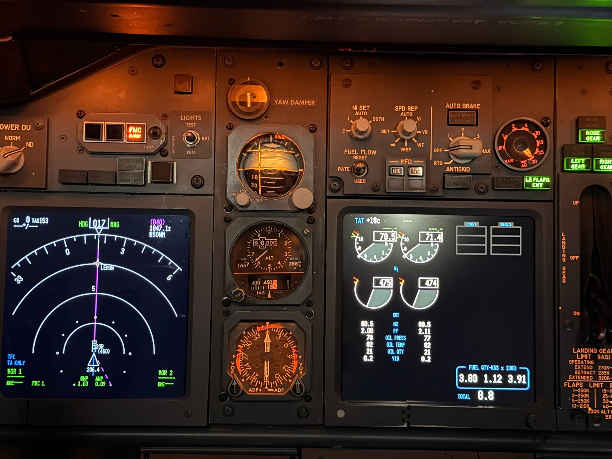
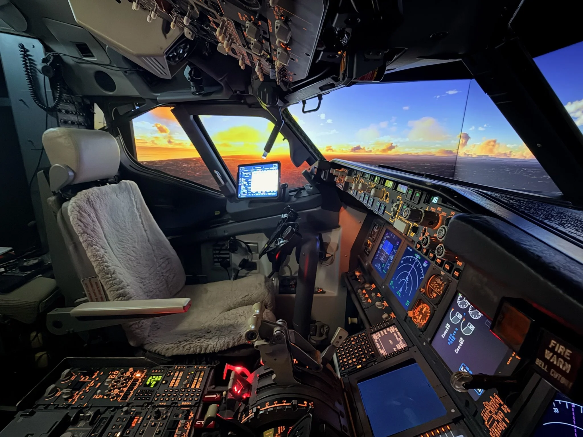
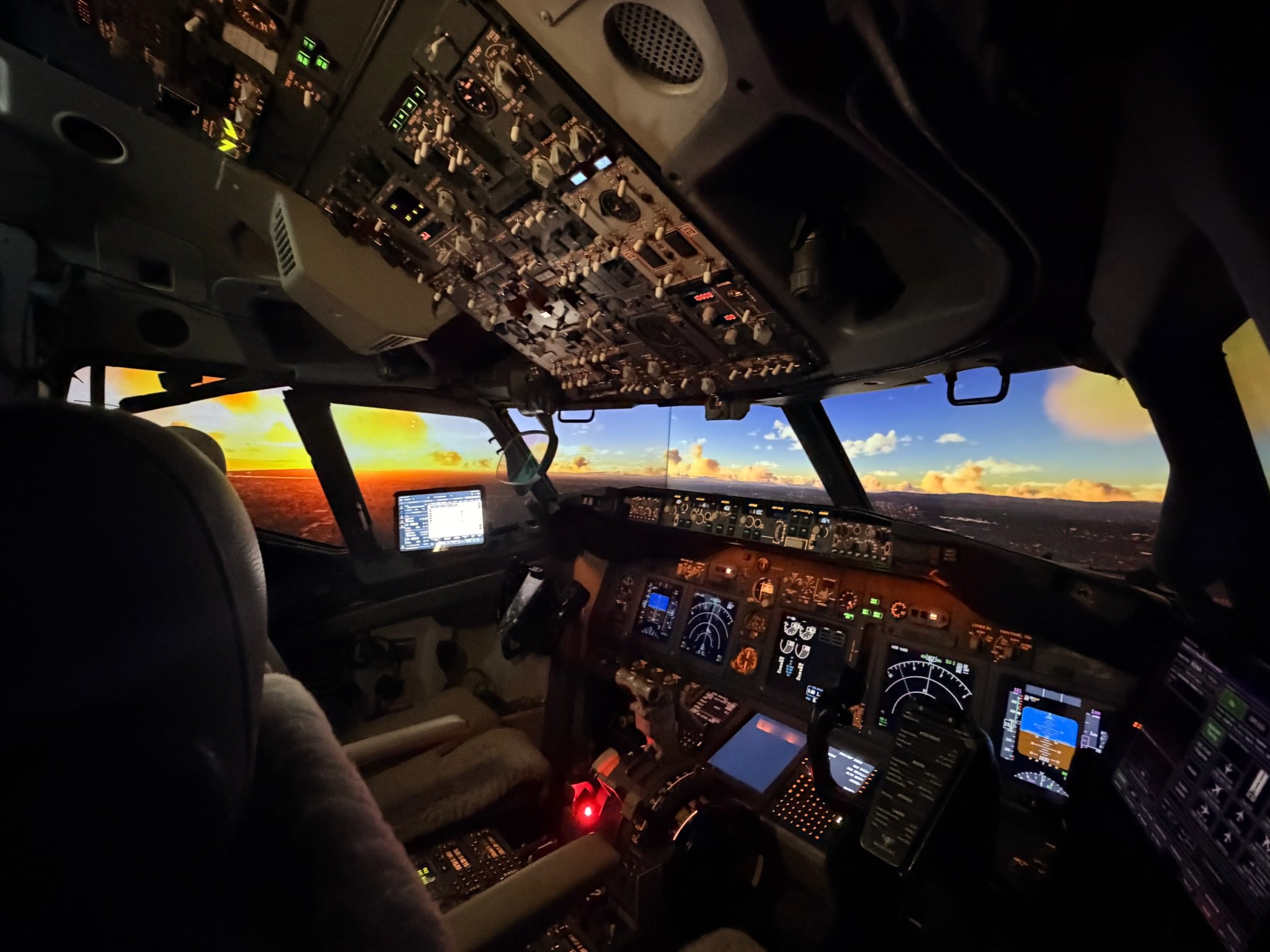
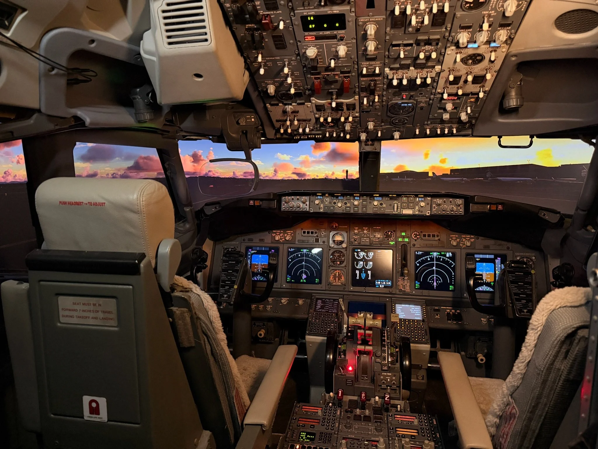
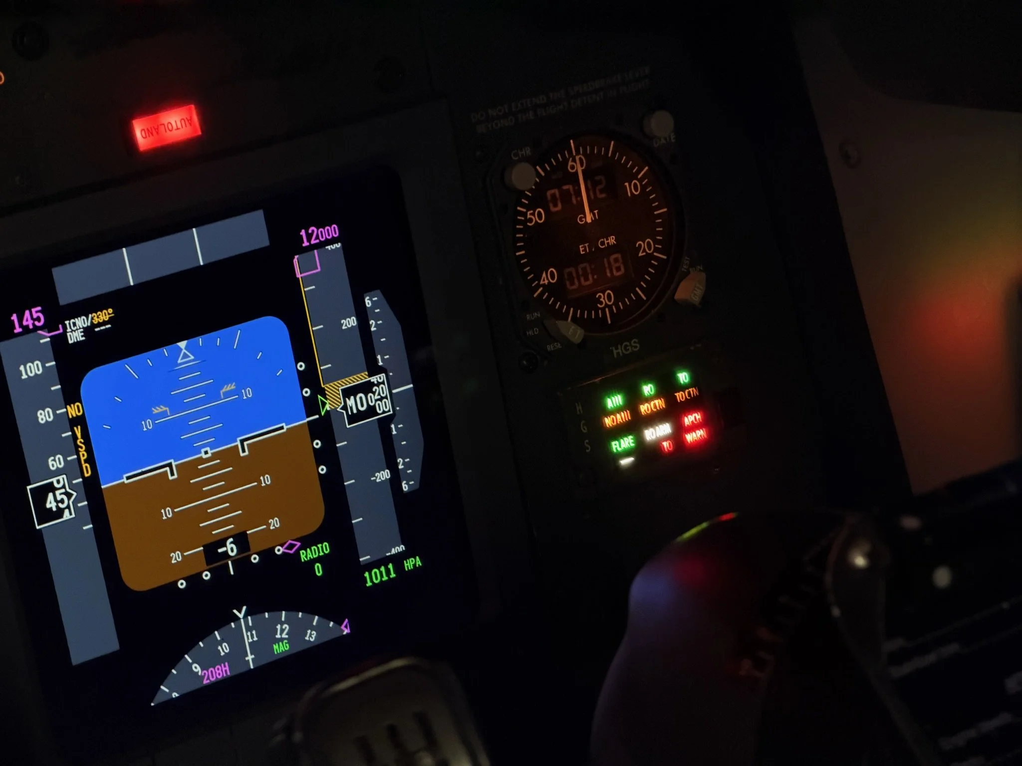
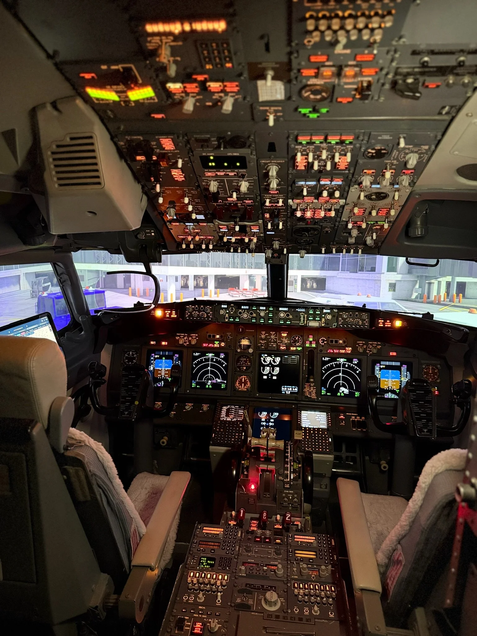
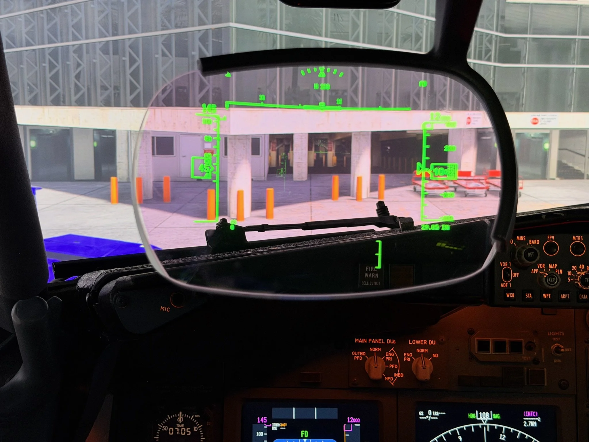
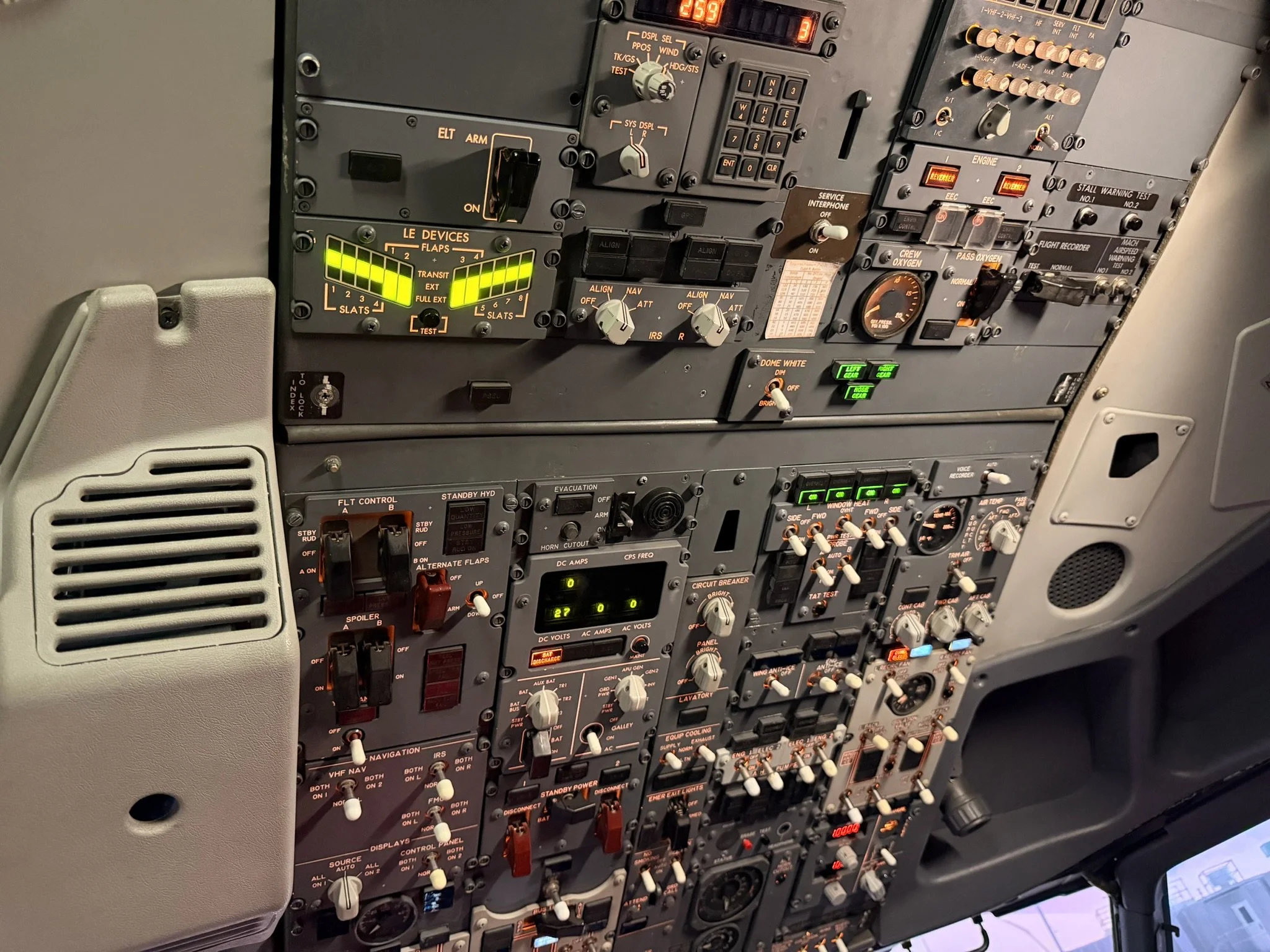
Enthusiast Showcase - Orange County 737 Sim

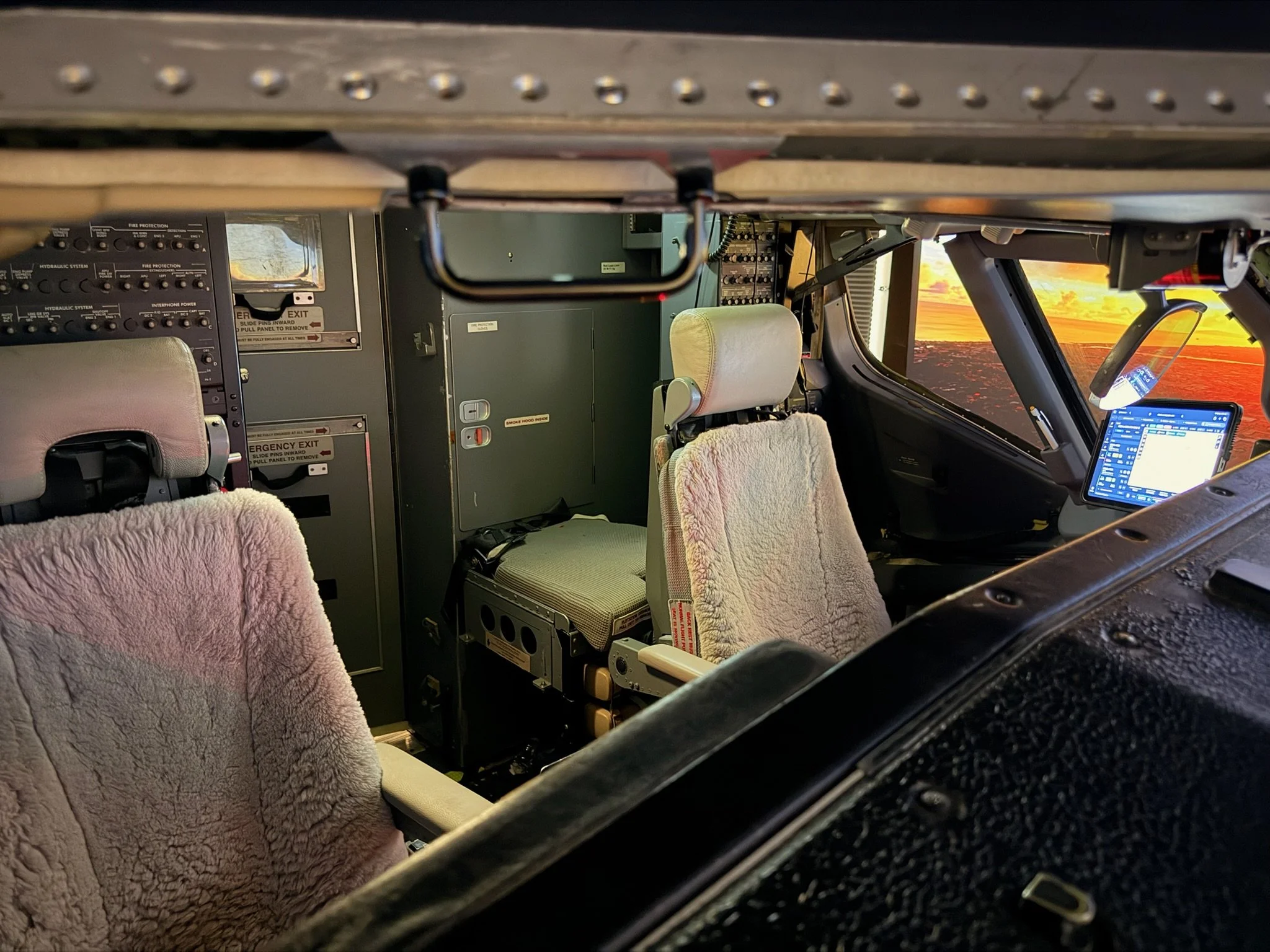
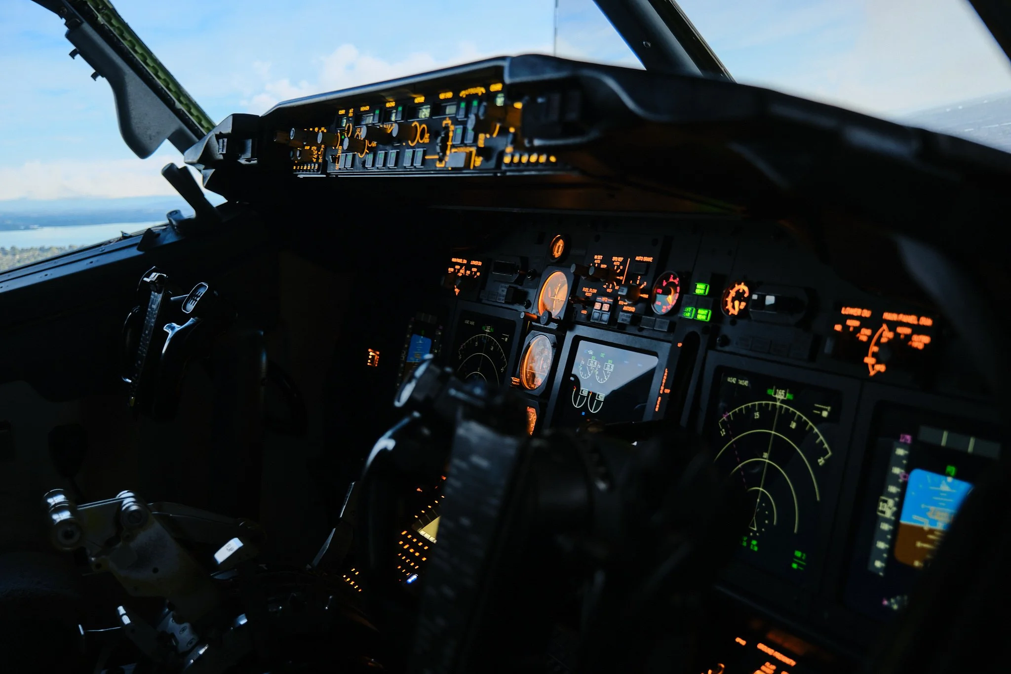
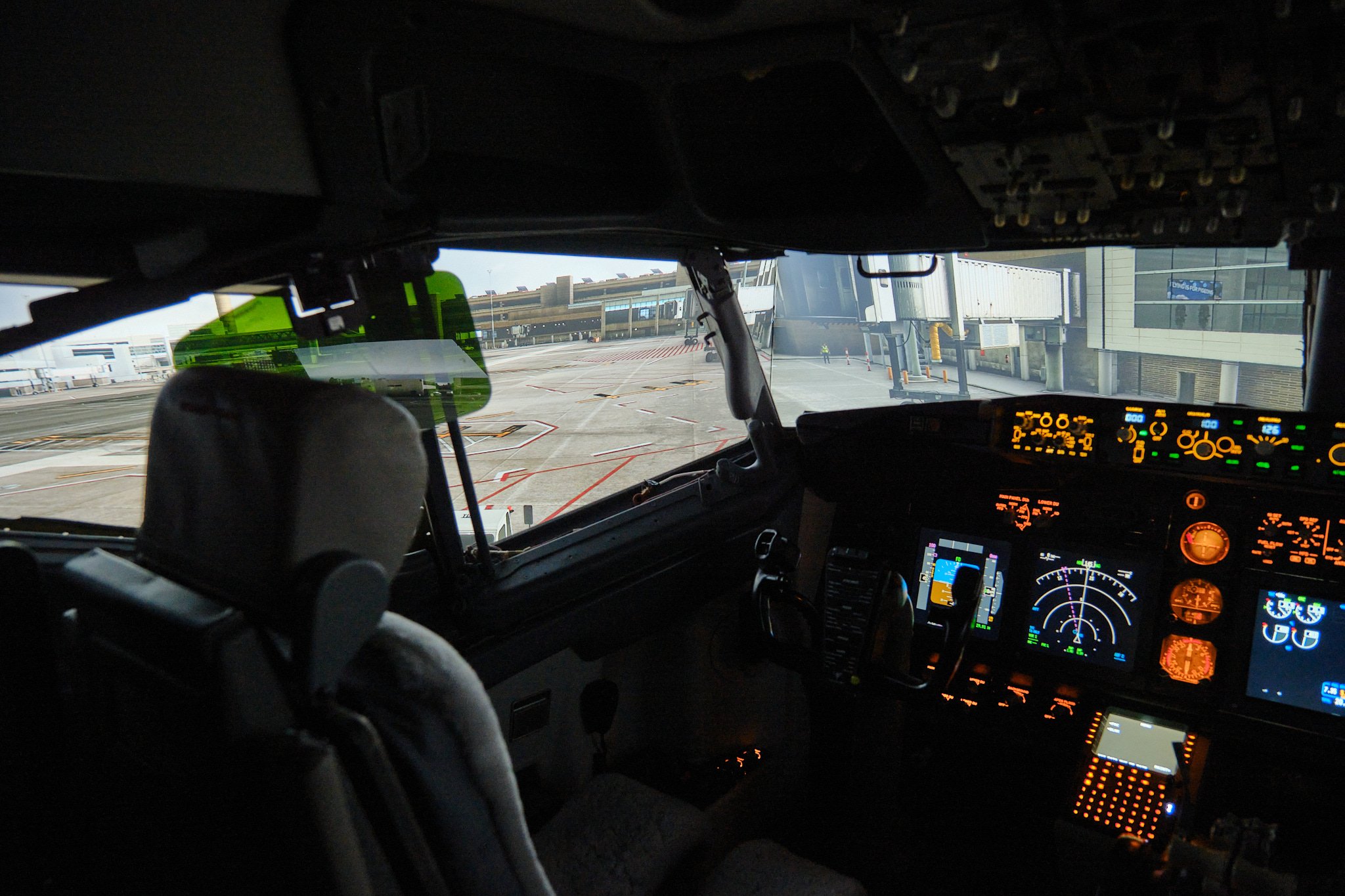
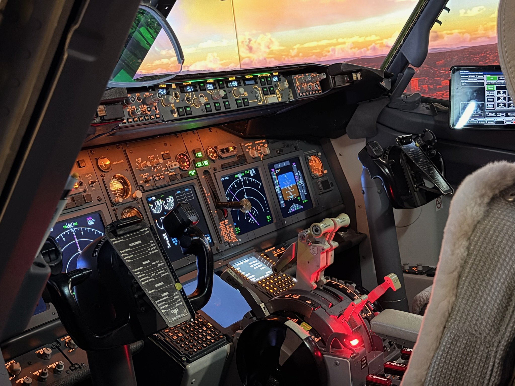
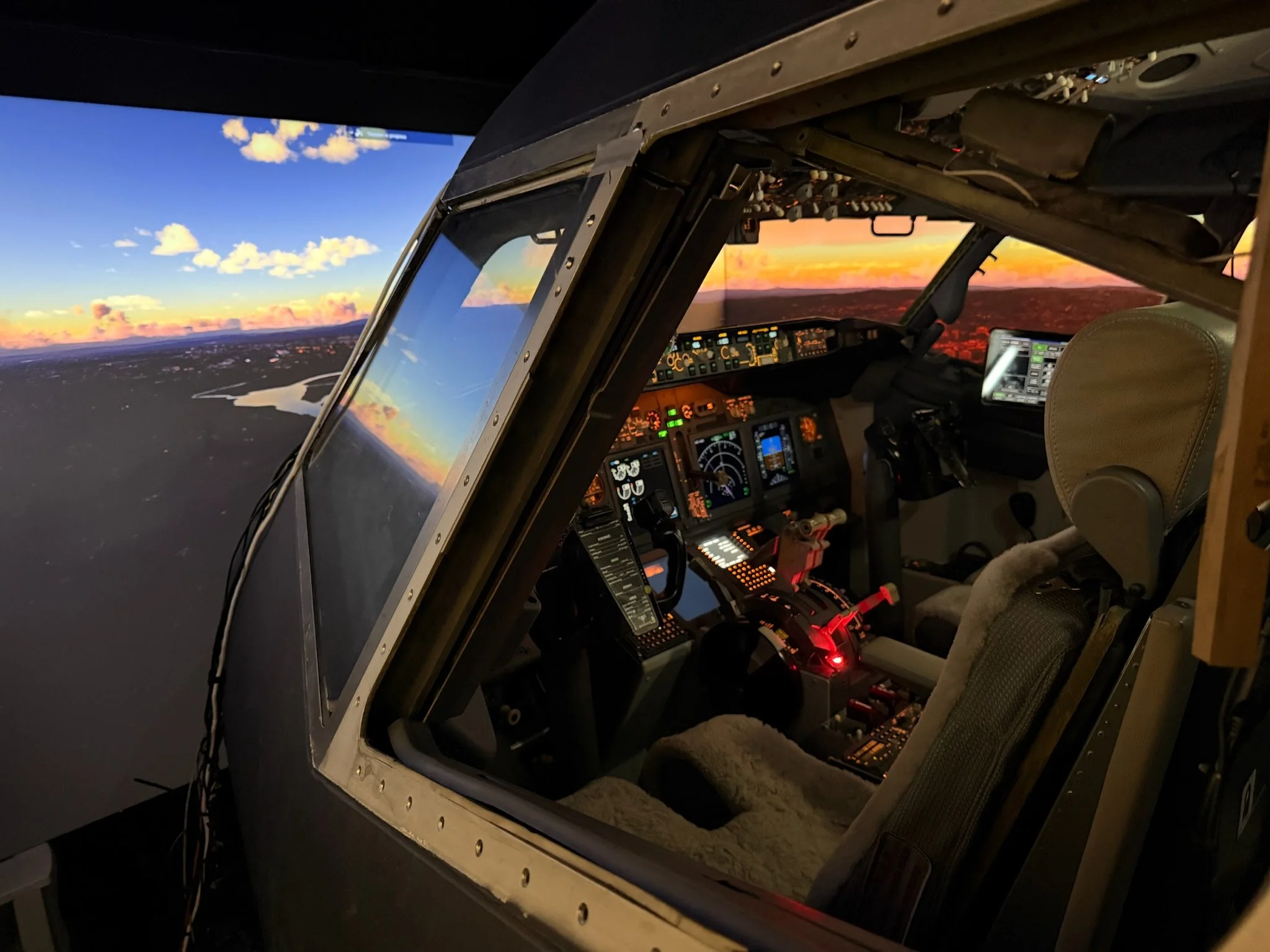
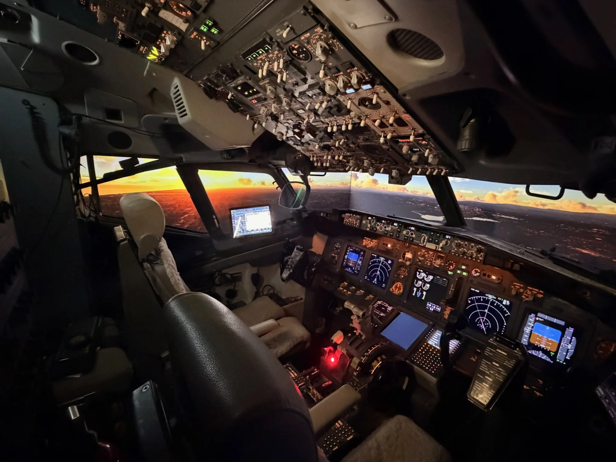
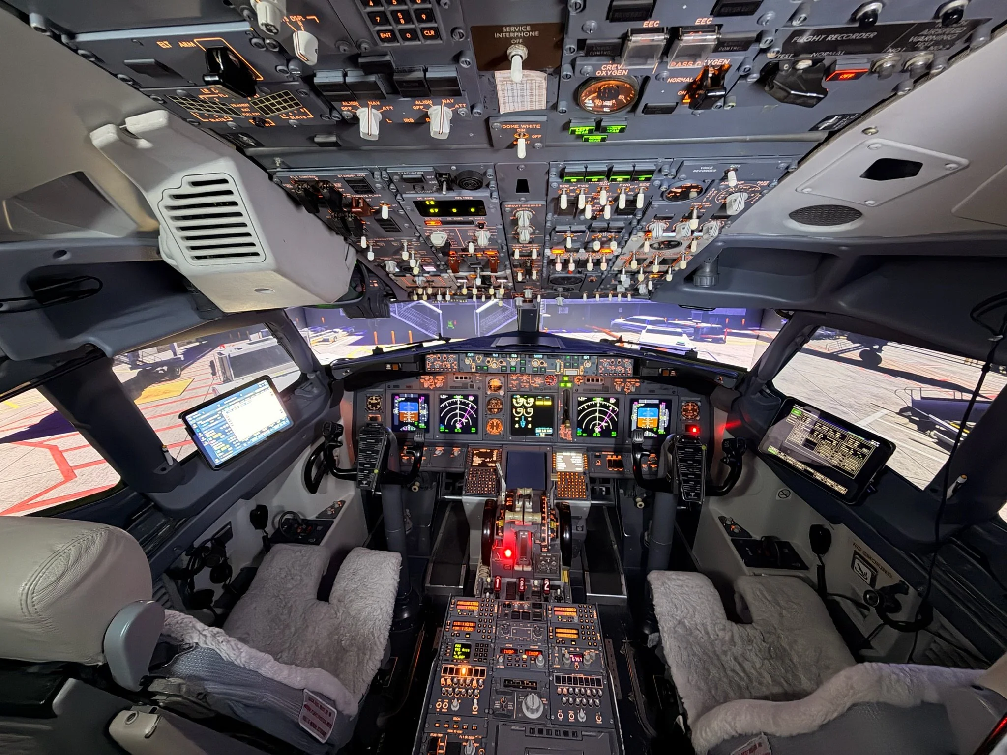
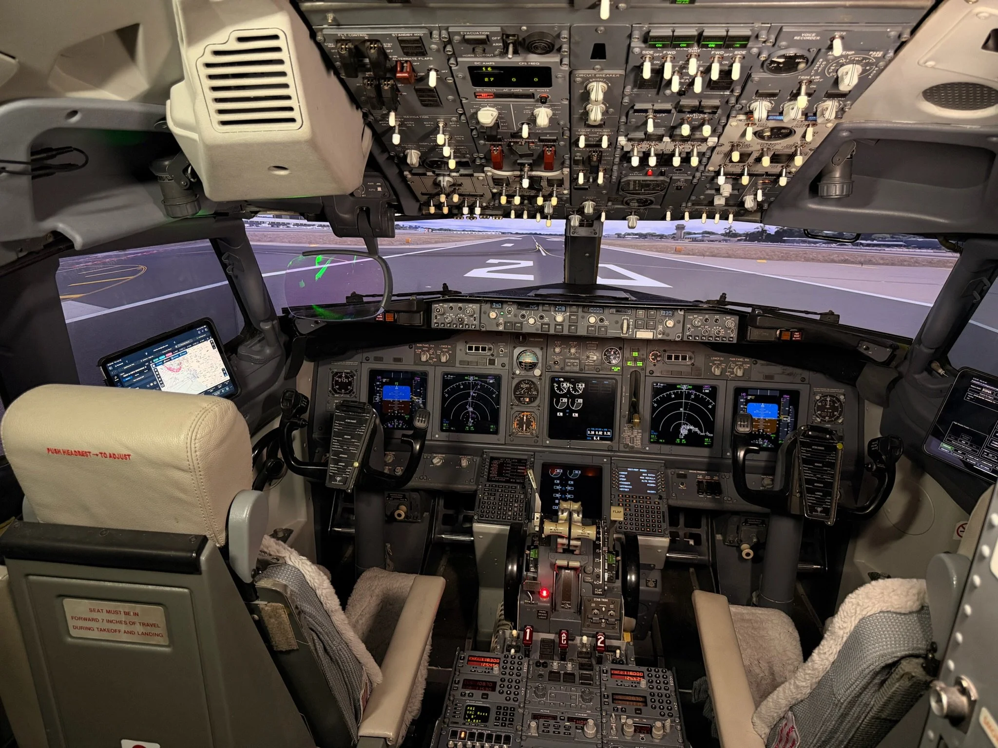
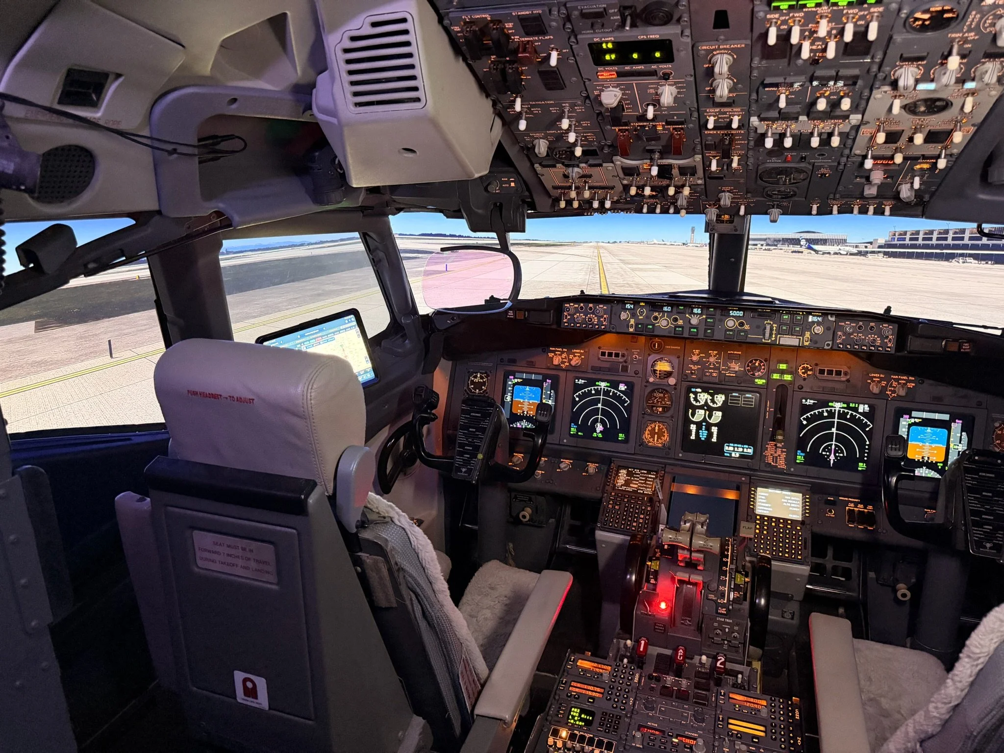
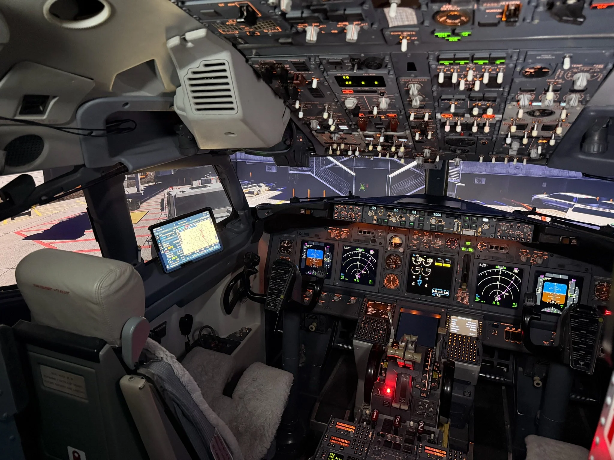
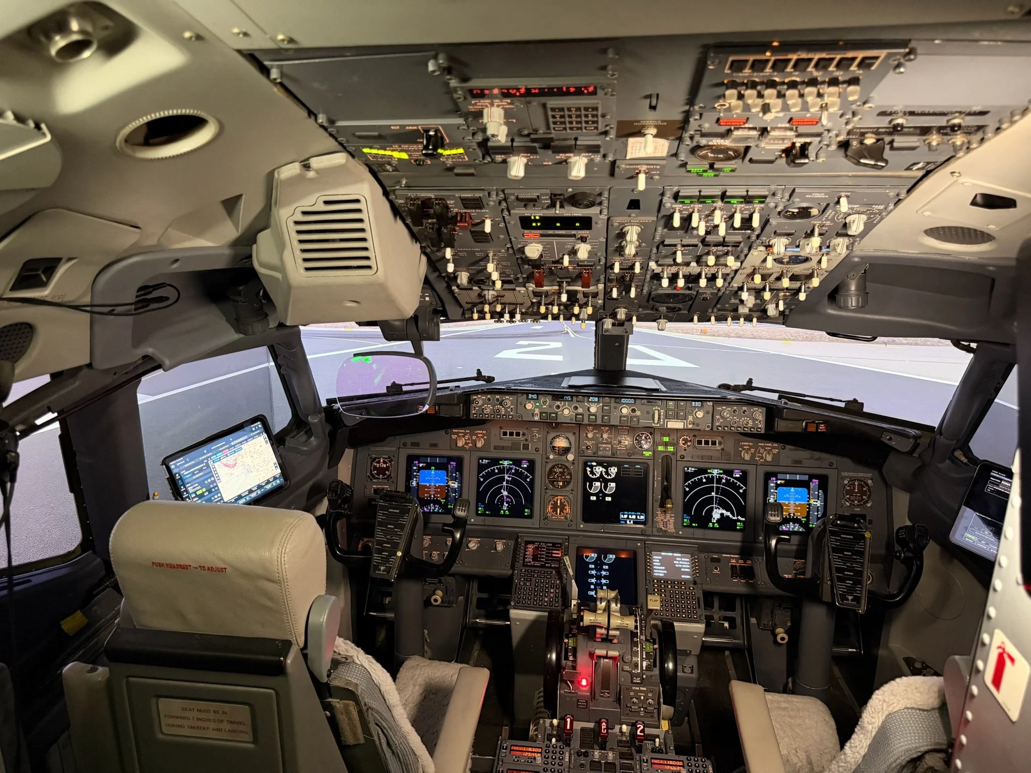
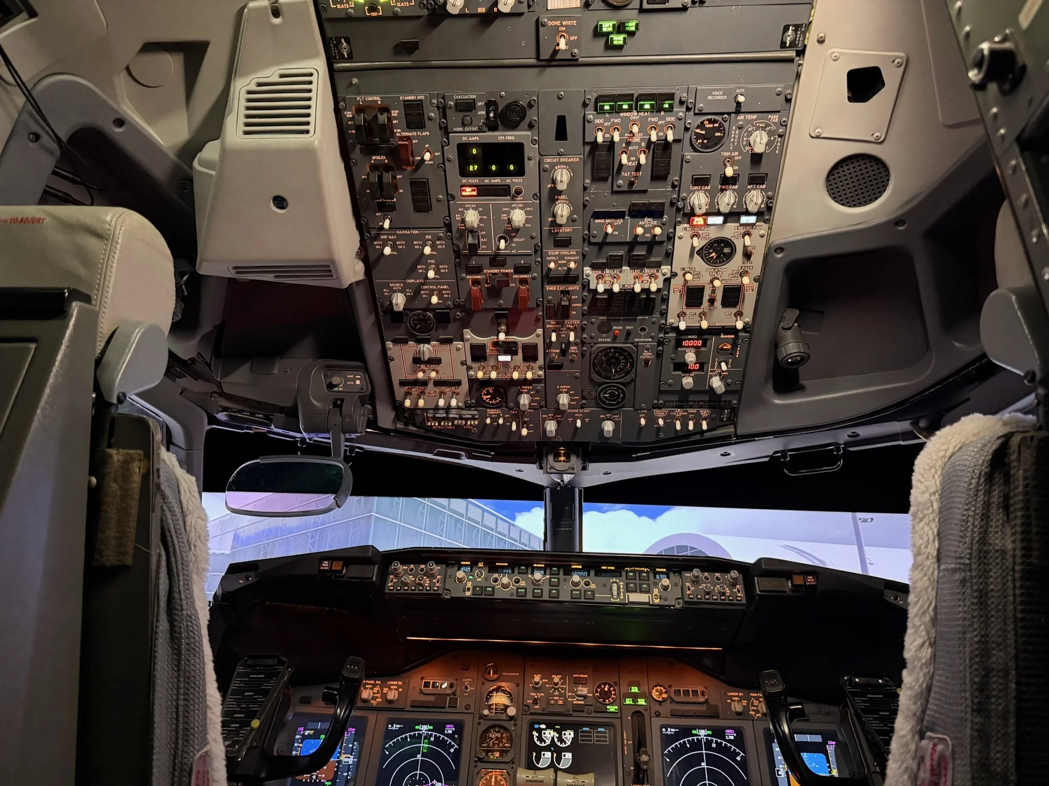
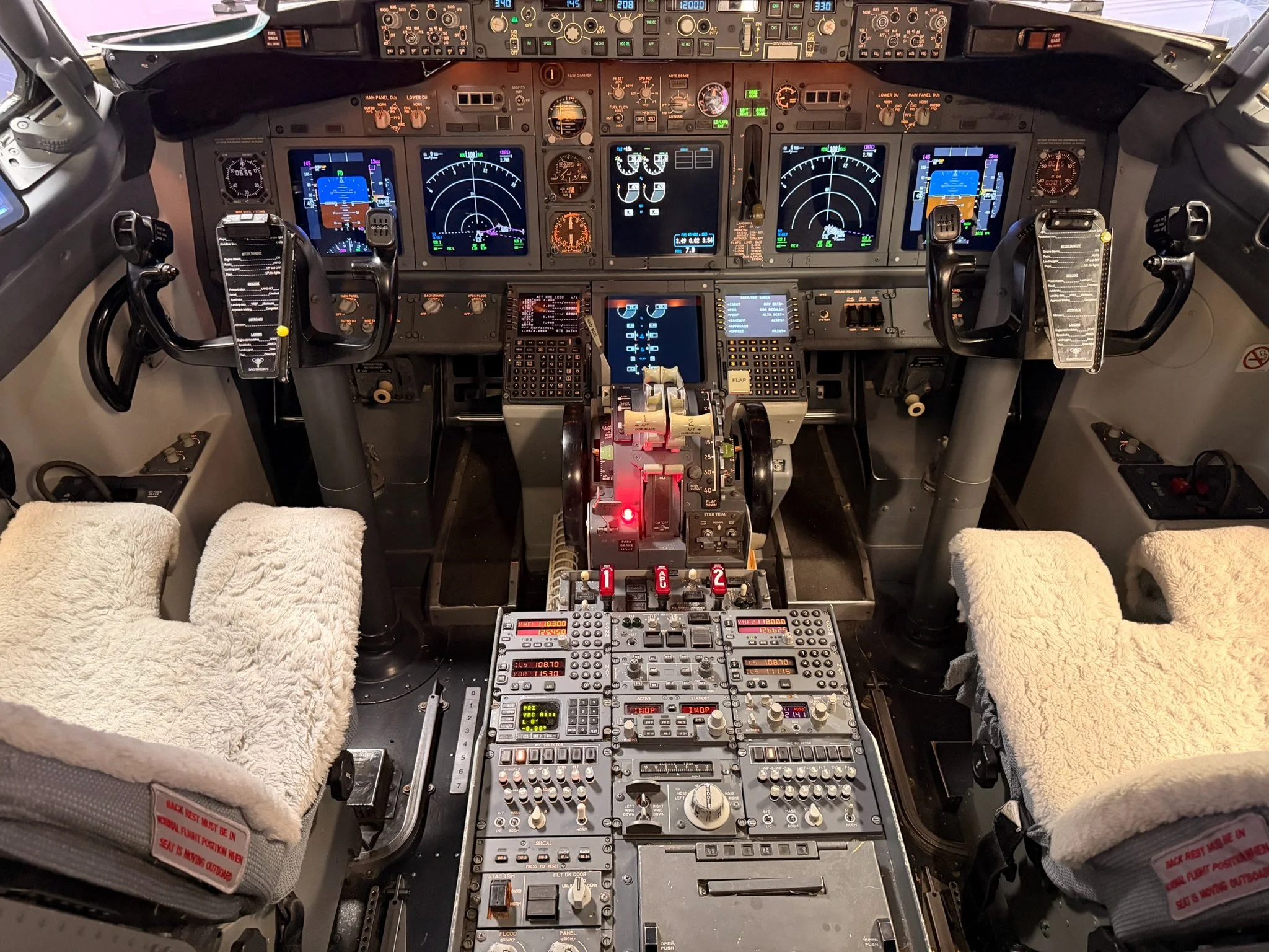
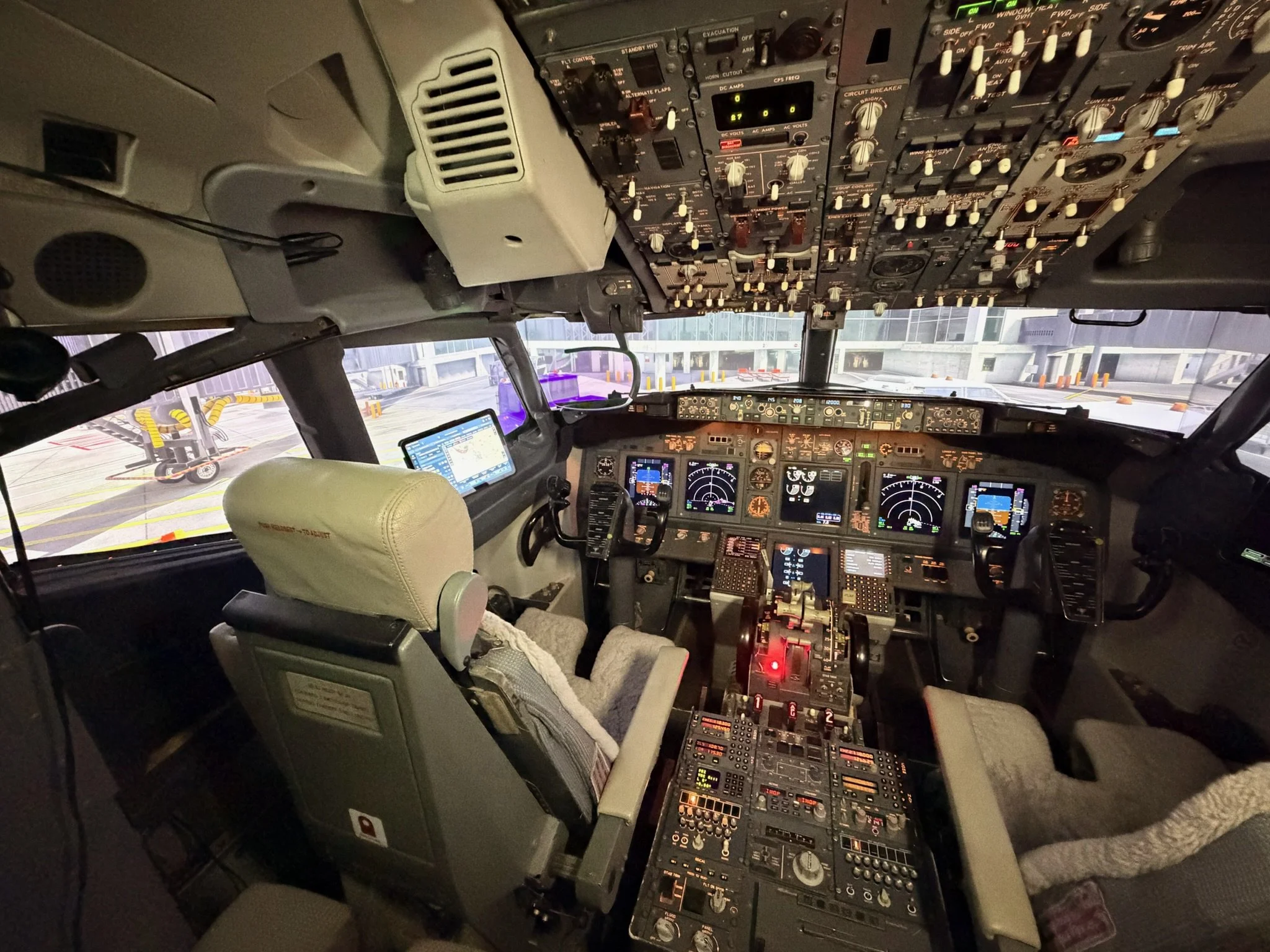
Periodically, I will showcase the work of other flight simulator enthusiasts. One of the most impressive setups I have come across is Orange County Sim in California.

Most 737 flight simulators in the hobbyist world are desktop‑based, typically built around the Microsoft Flight Simulator platform and enhanced with PMDG’s highly detailed aircraft models. Beyond these conventional setups lies a wide spectrum of home built simulators whose construction quality, functionality, and realism vary dramatically; some only loosely resemble the actual aircraft.

For many enthusiasts, the ultimate ambition is a high‑fidelity 737 replica enclosed within an airliner style cockpit shell. To support this goal, companies such as Flight Deck Solutions, CP Flight, and SimWorld offer dual‑seat training devices that can be purchased as complete units or integrated into full cockpit shells using purpose built liners.

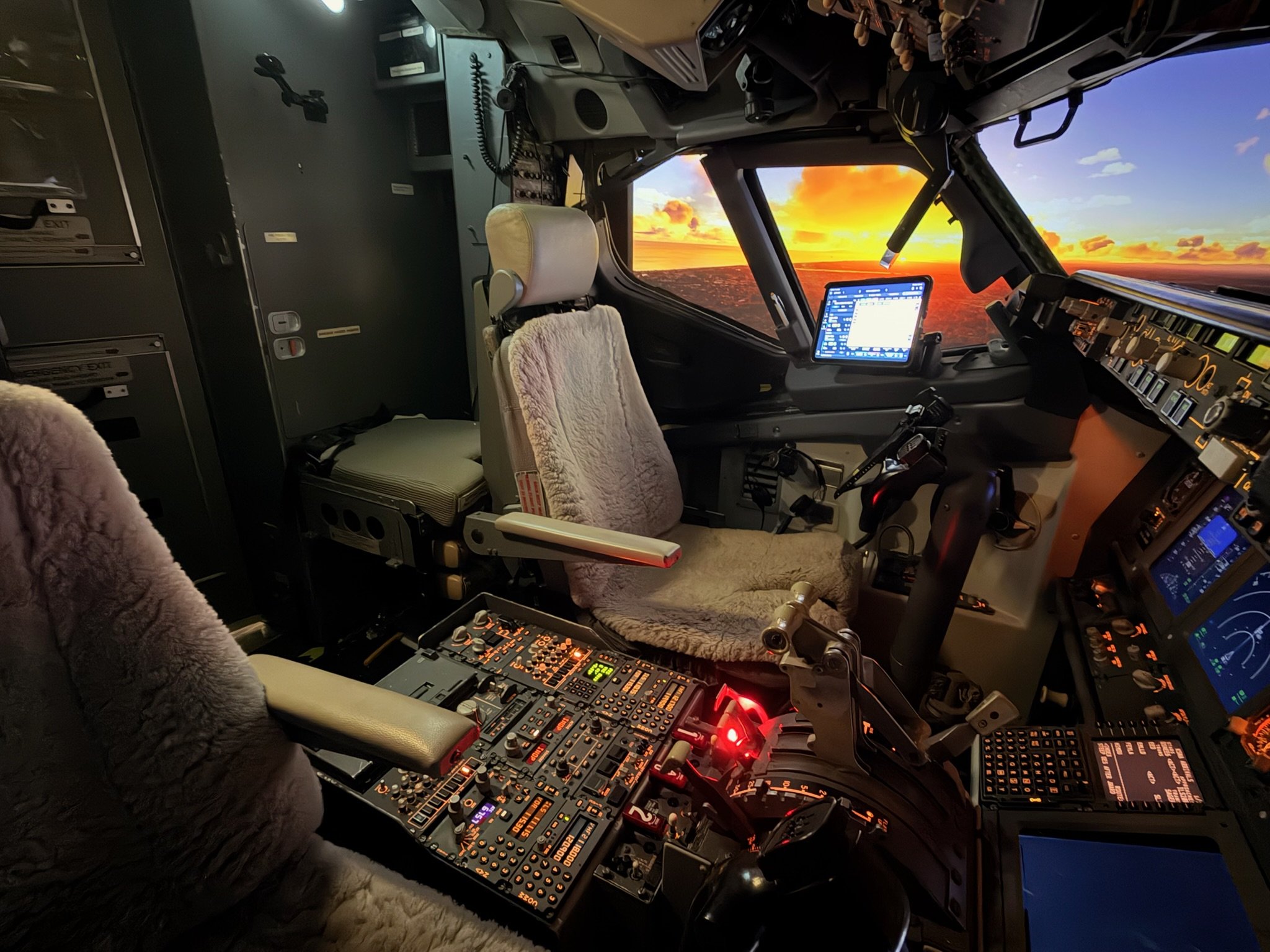
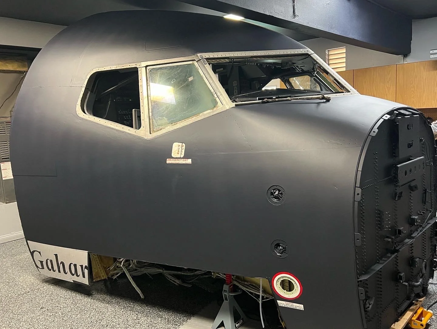
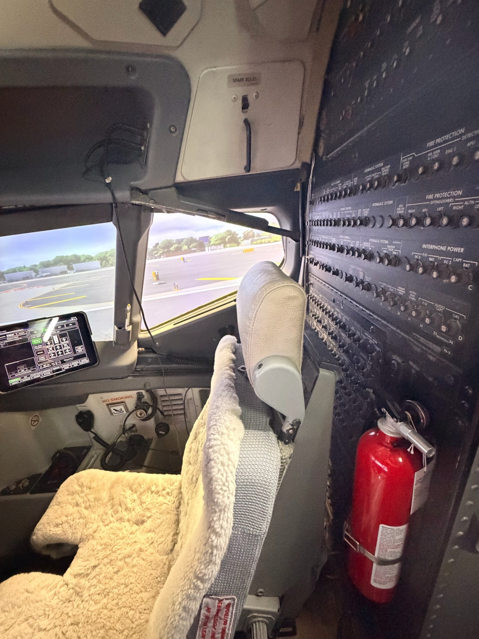
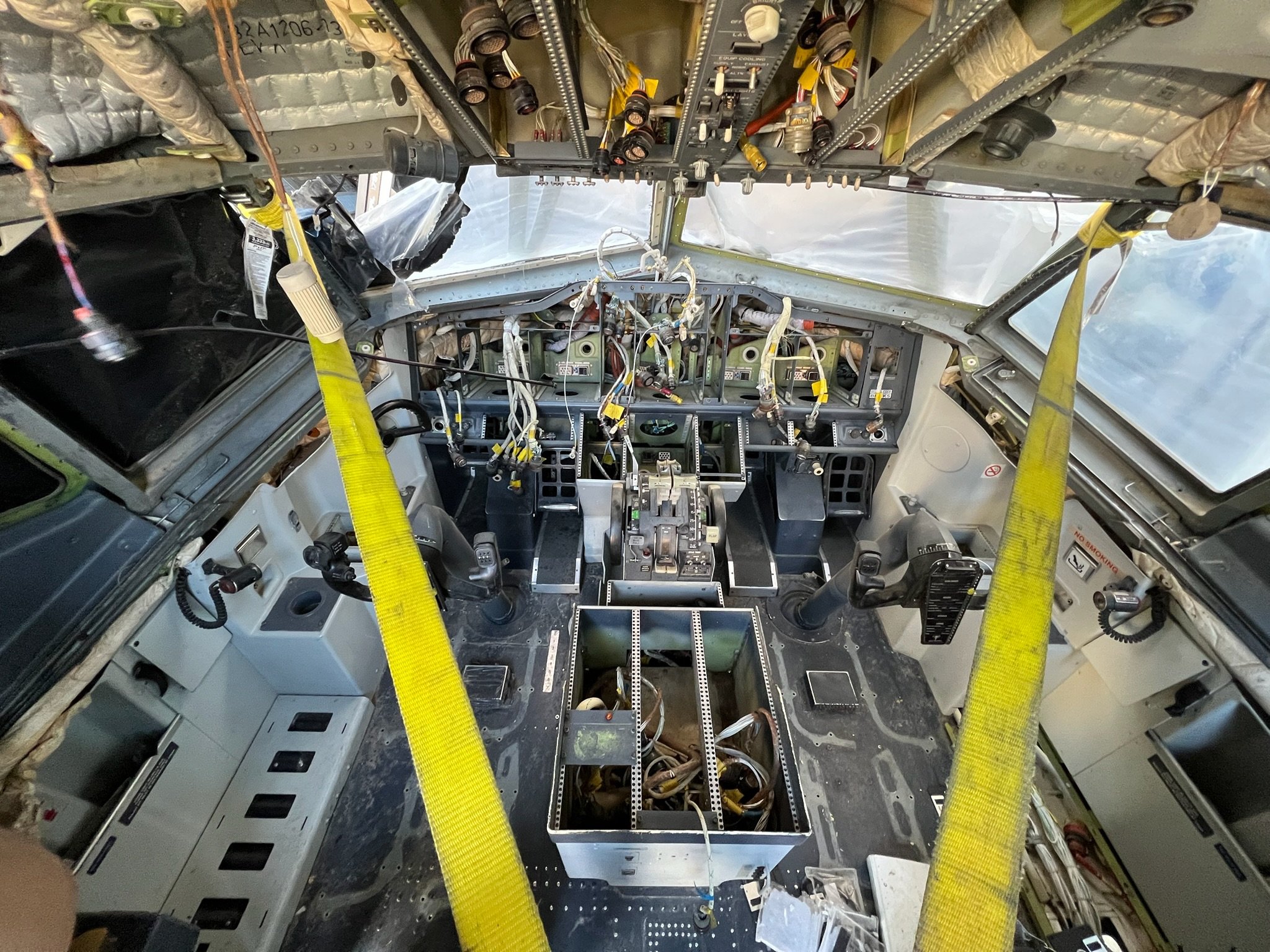
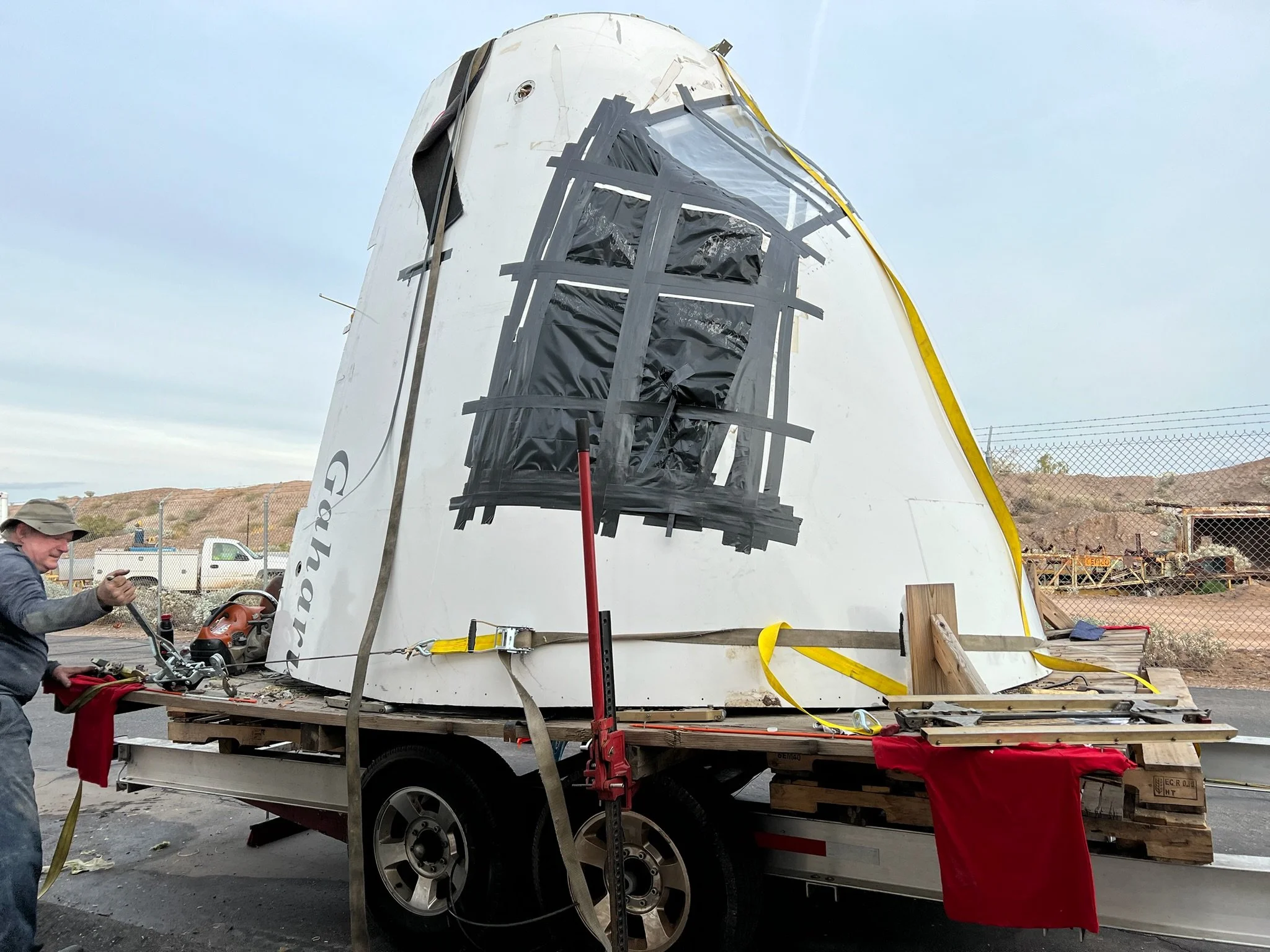
Simulators incorporating a high number of genuine aircraft components (OEM parts) are relatively rare in the hobby, and complete OEM flight decks, outside of certified Level‑D commercial simulators, are rarer still. For the most dedicated builders, the pinnacle achievement is converting an OEM flight deck housed within a retired airliner’s nose section for use with Microsoft Flight Simulator or Lockheed Martin’s Prepar3D.

Orange County 737 Sim

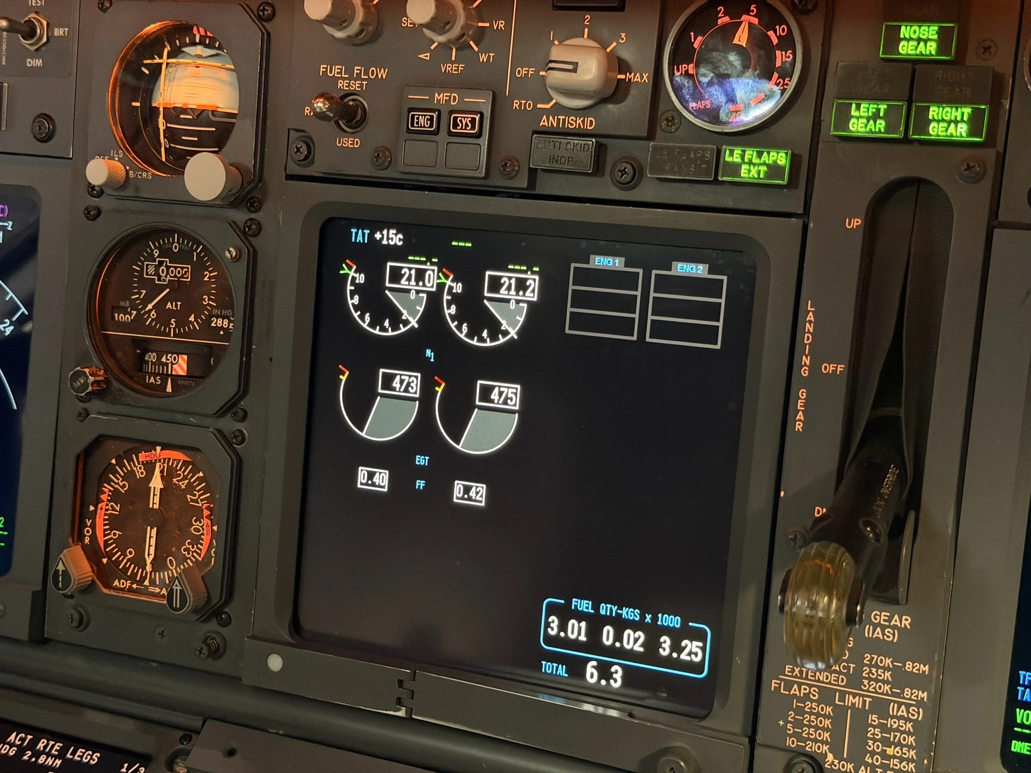
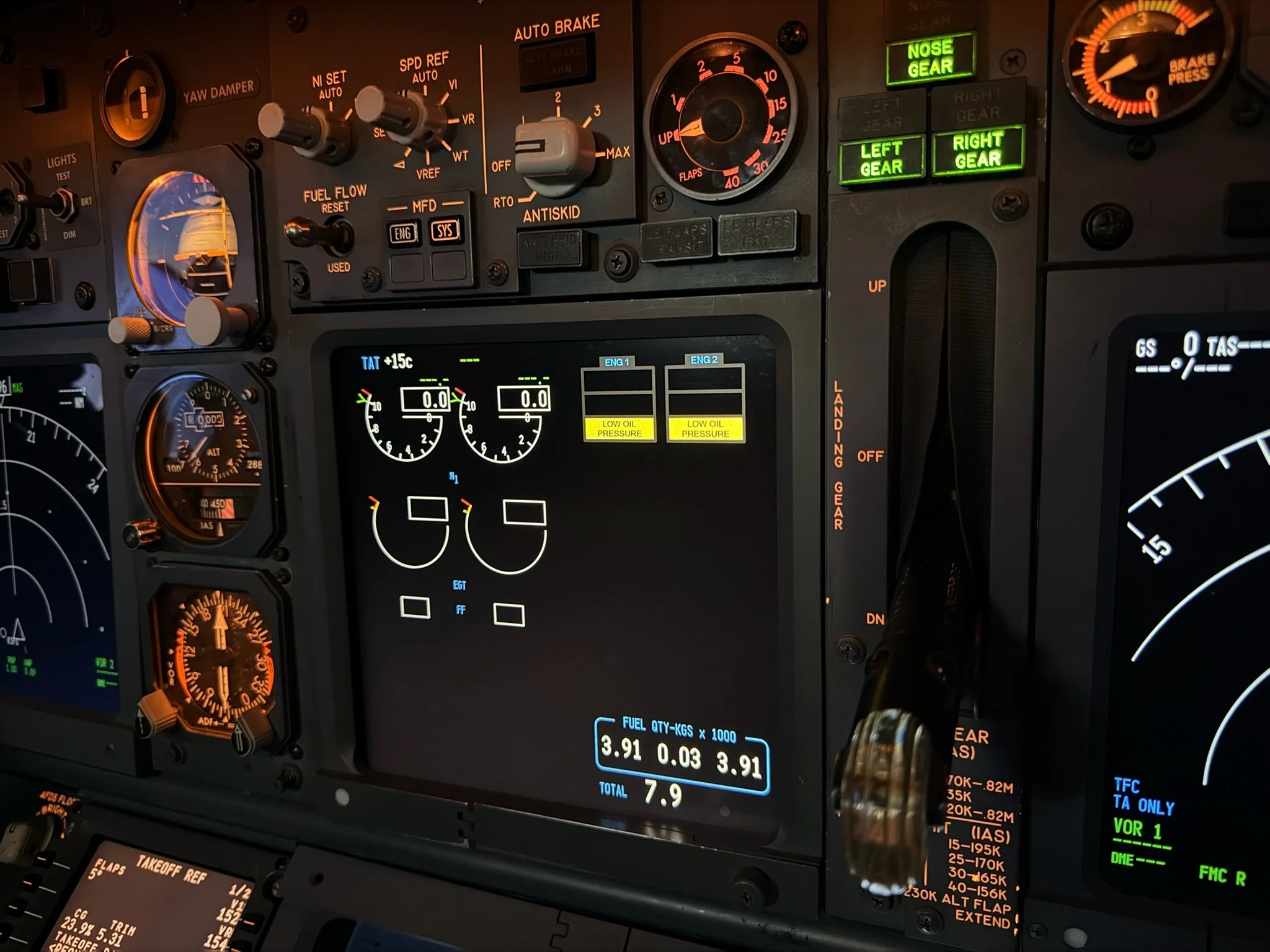
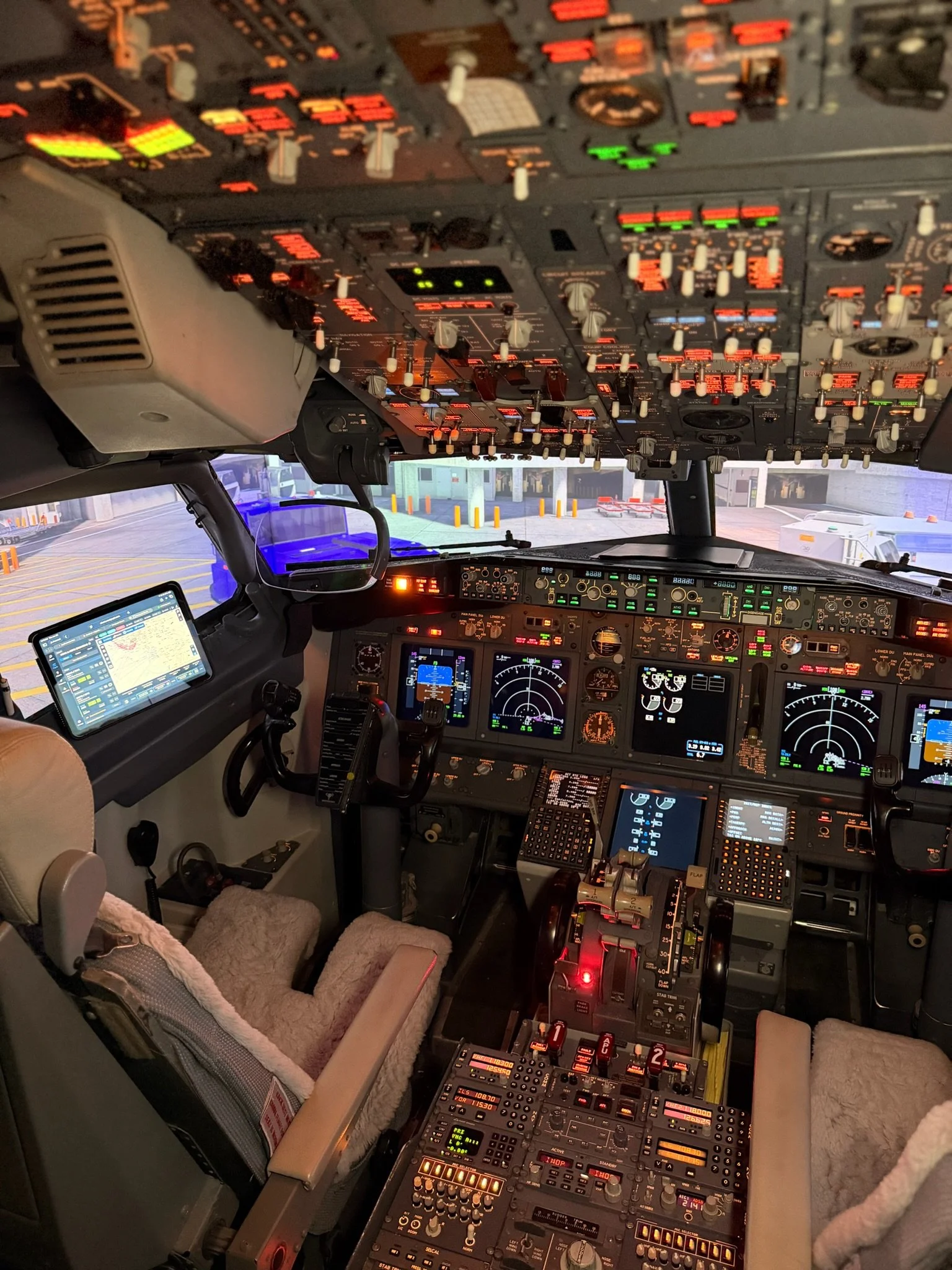
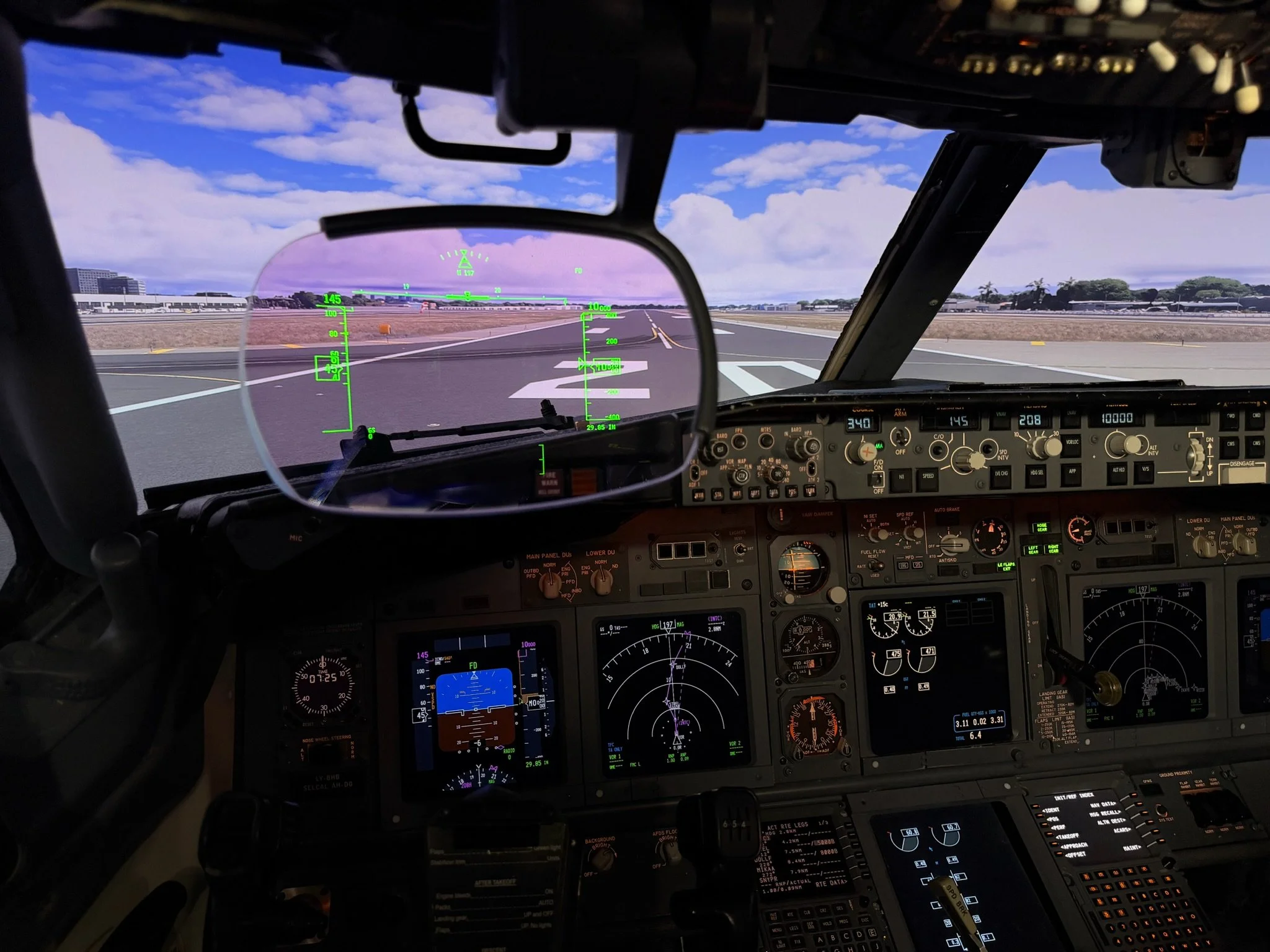
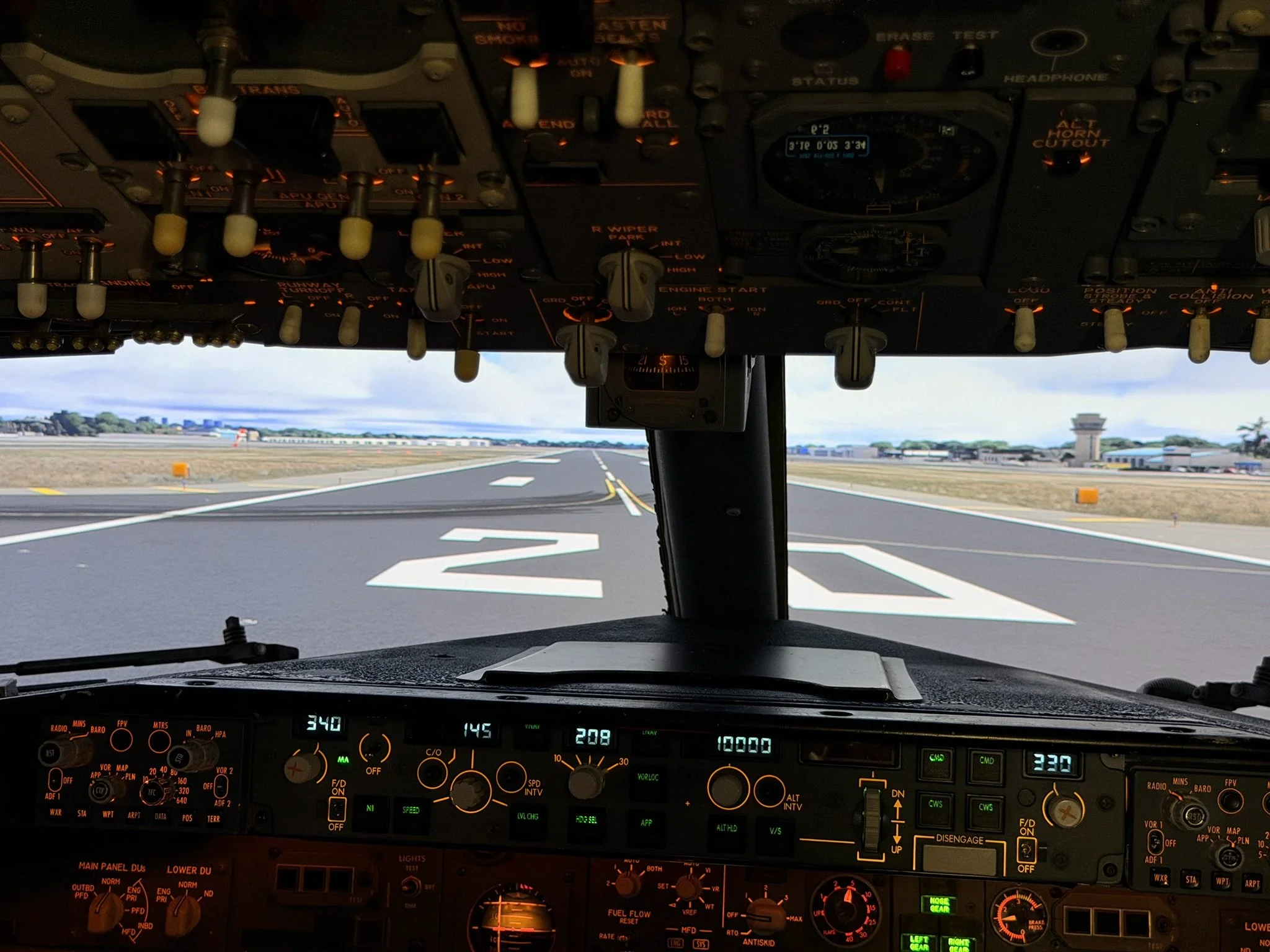
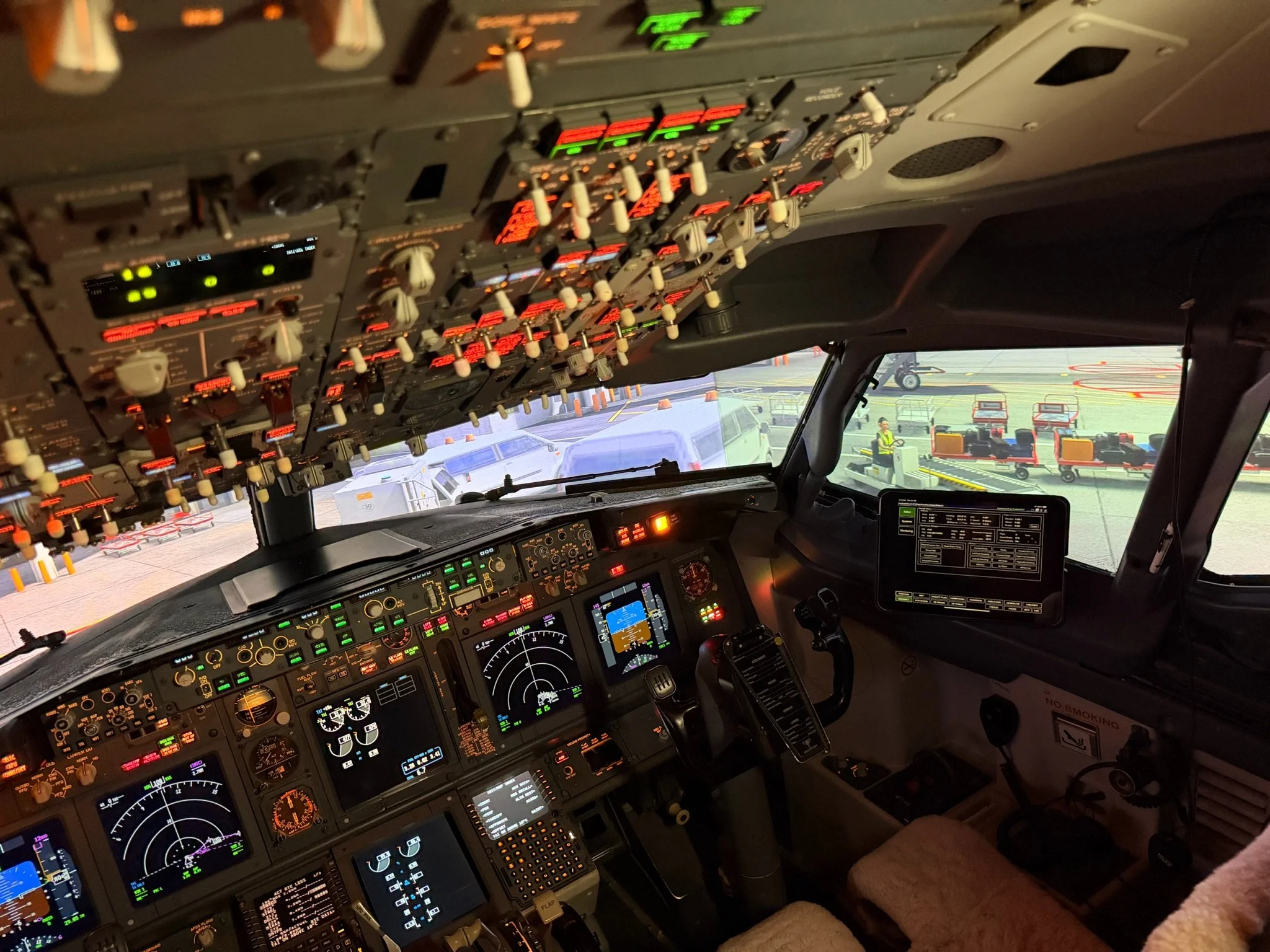
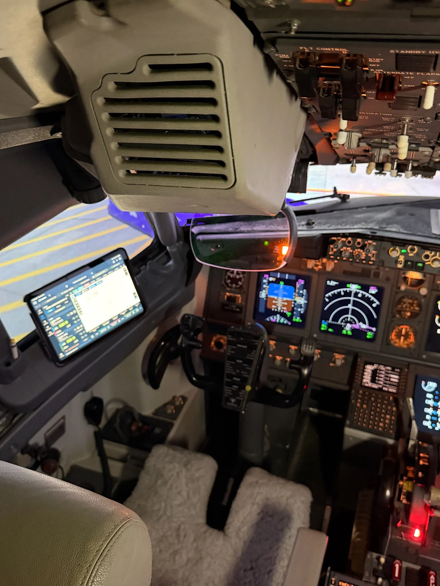
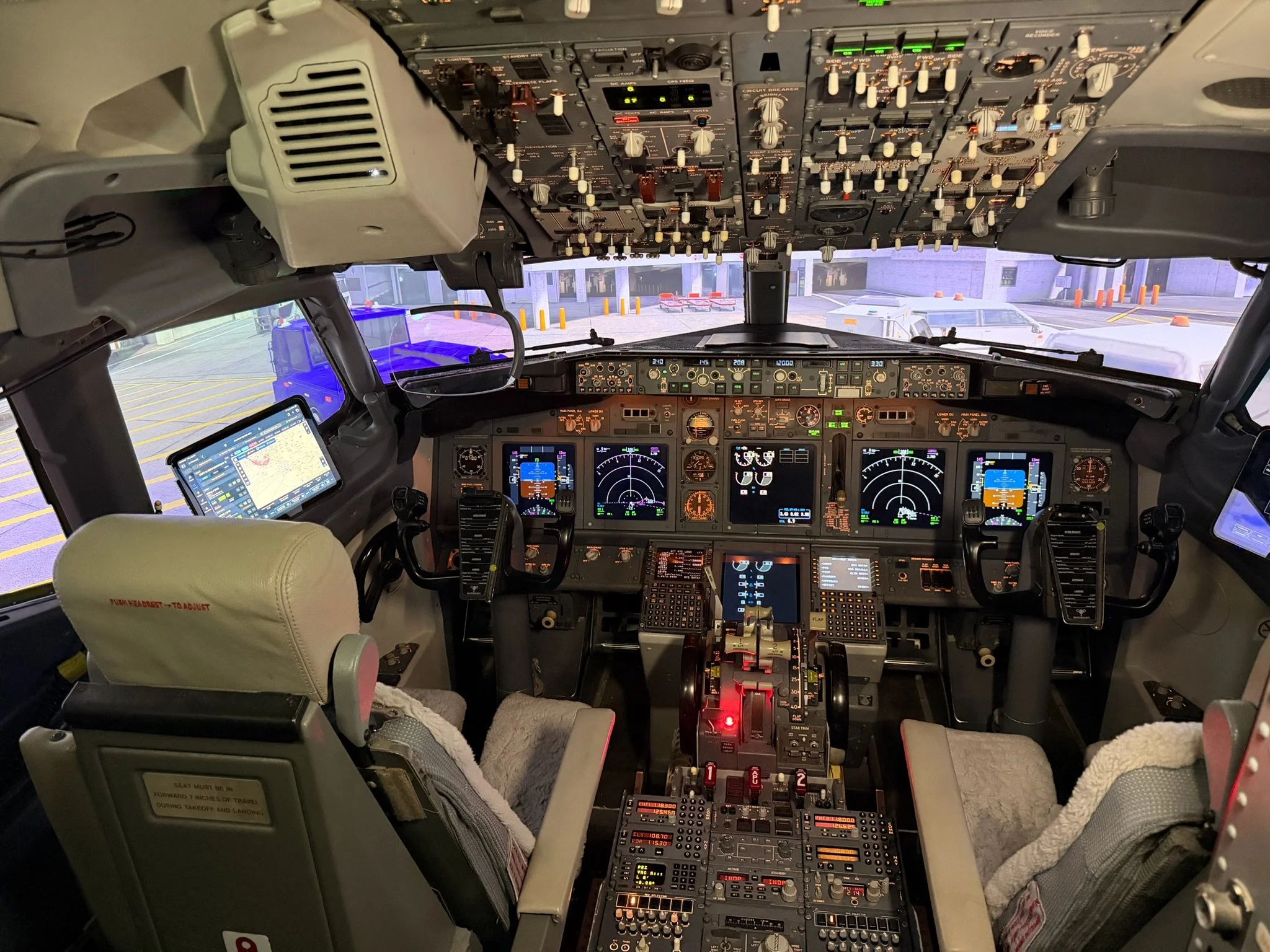
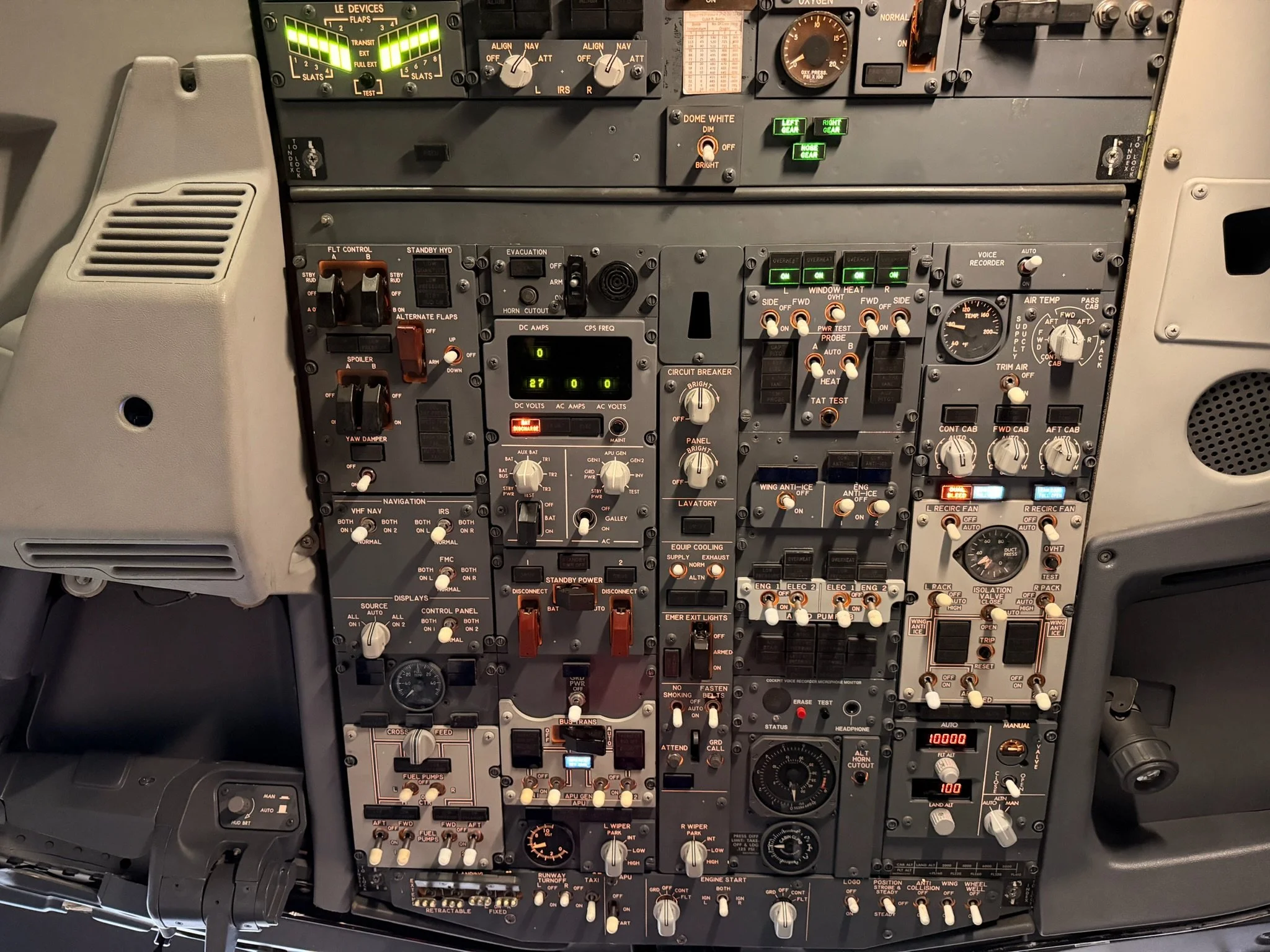
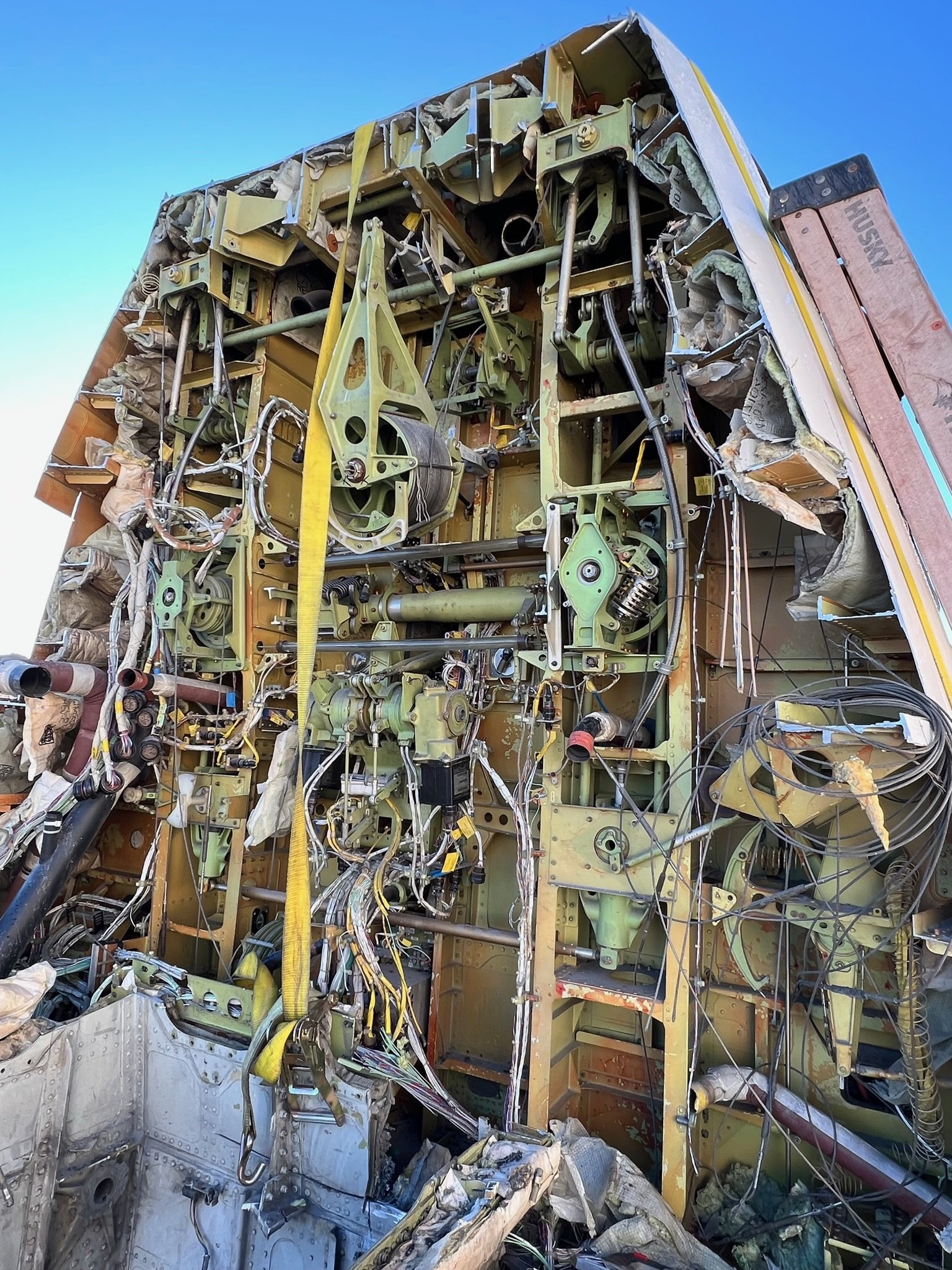
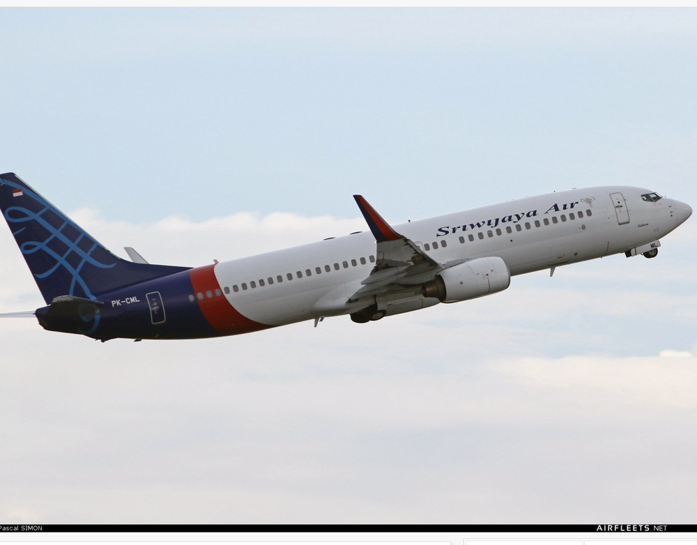
Among the most impressive examples of this craftsmanship is Orange County Sim, widely regarded as the apex of home built 737 simulator projects. The simulator represents several years of meticulous engineering, refinement, and problem solving by its owner. The aircraft that has been used in the simulator is a Boeing 737‑800 that once flew for Sriwijaya Air (MSN 30636), before being dismantled in Arizona.

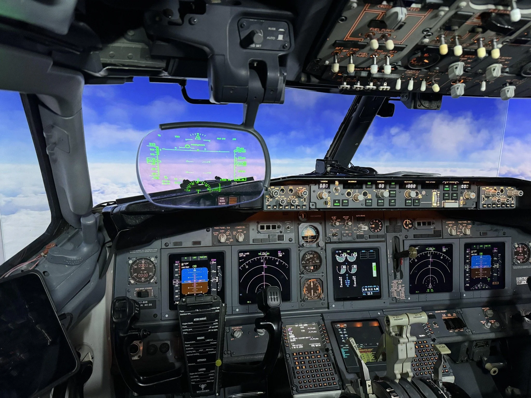
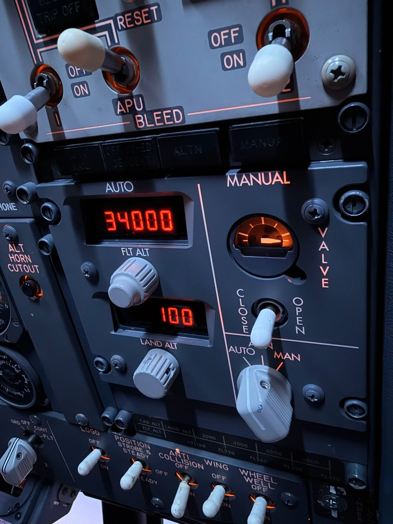
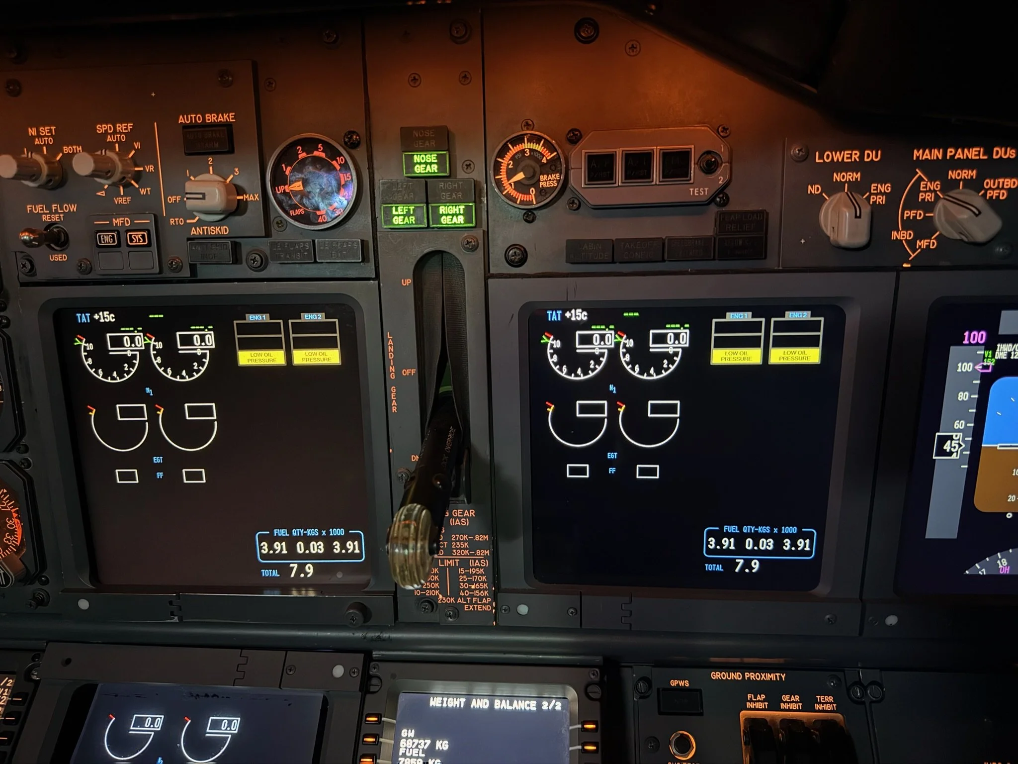
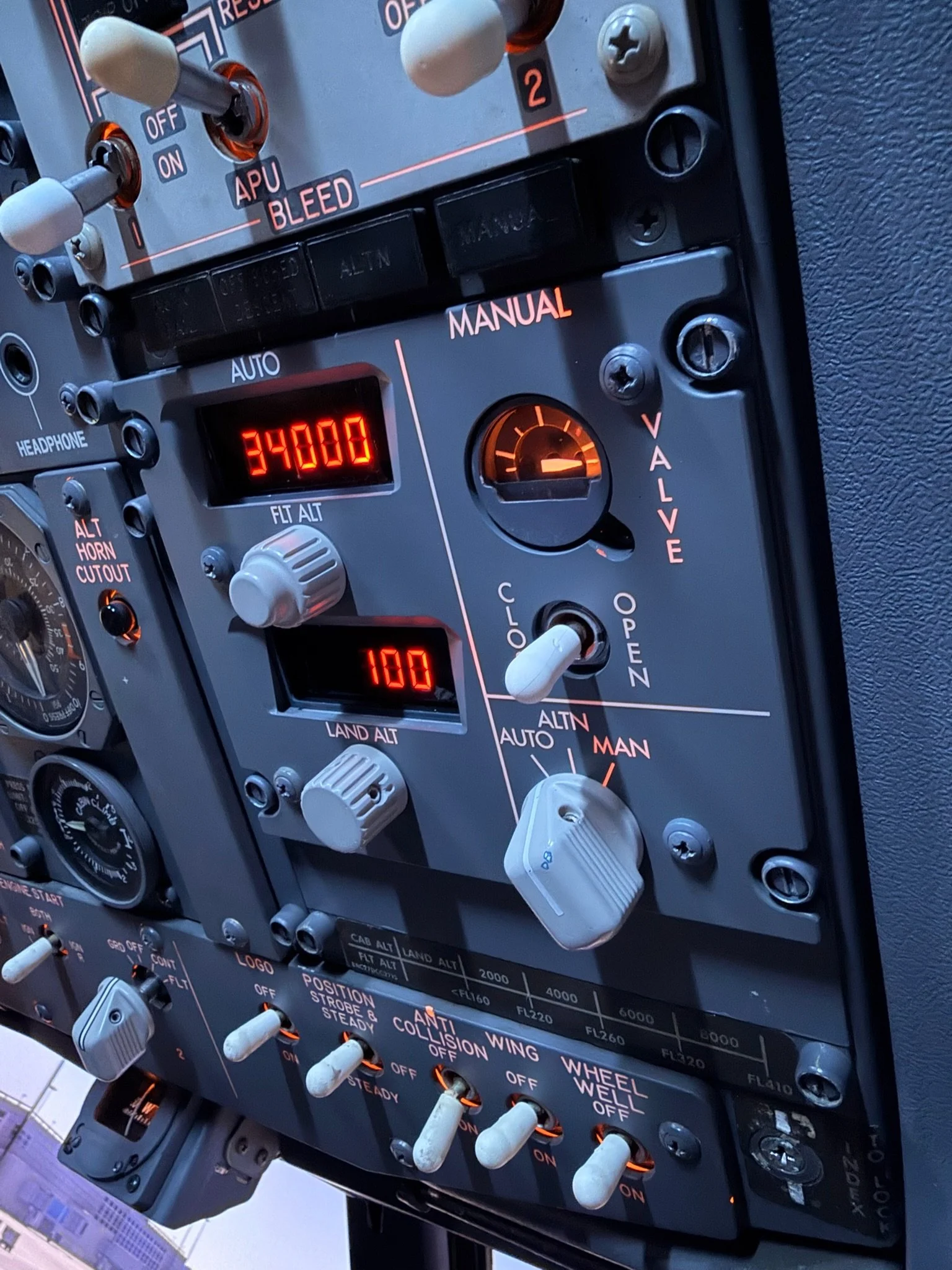
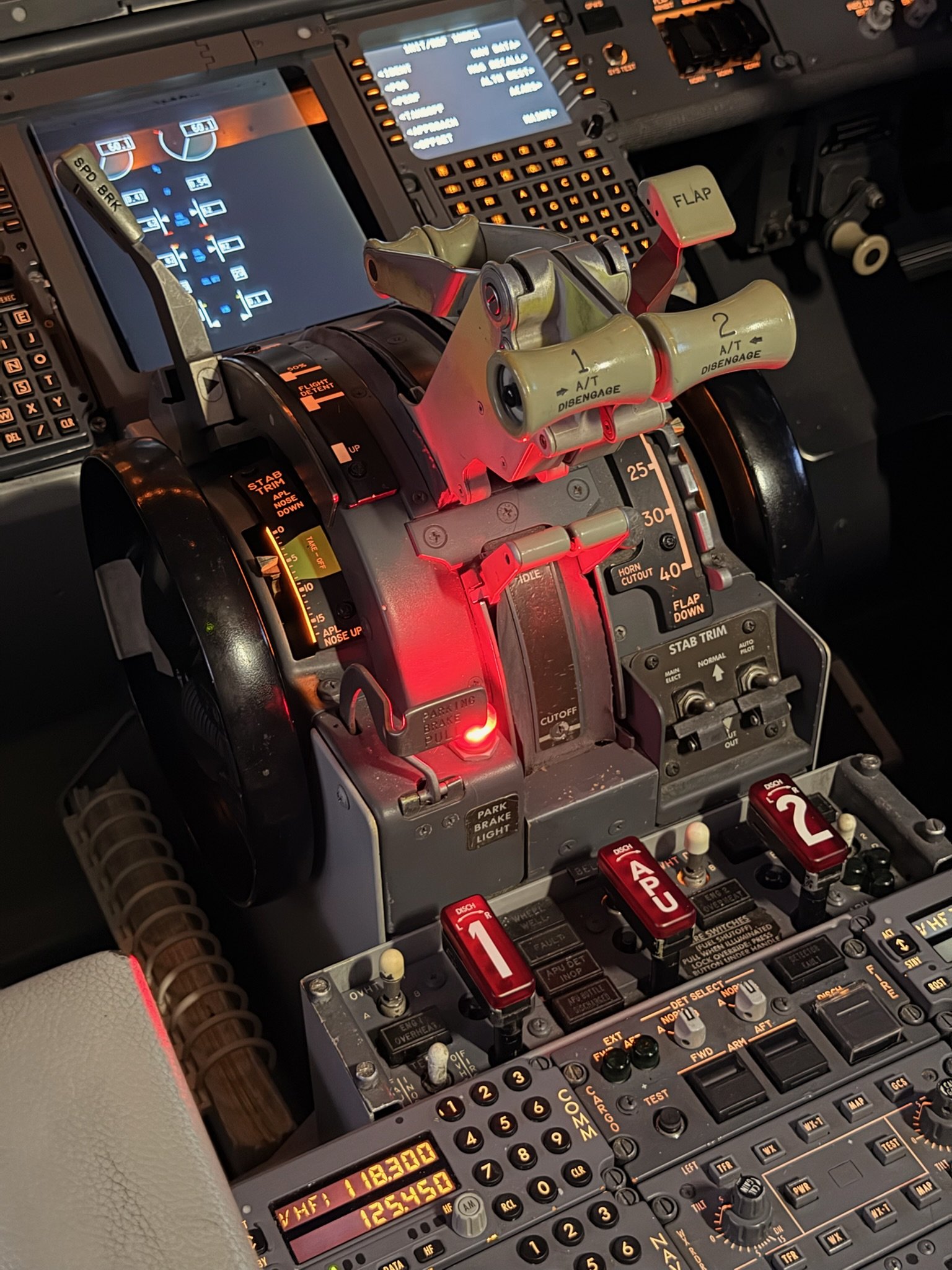
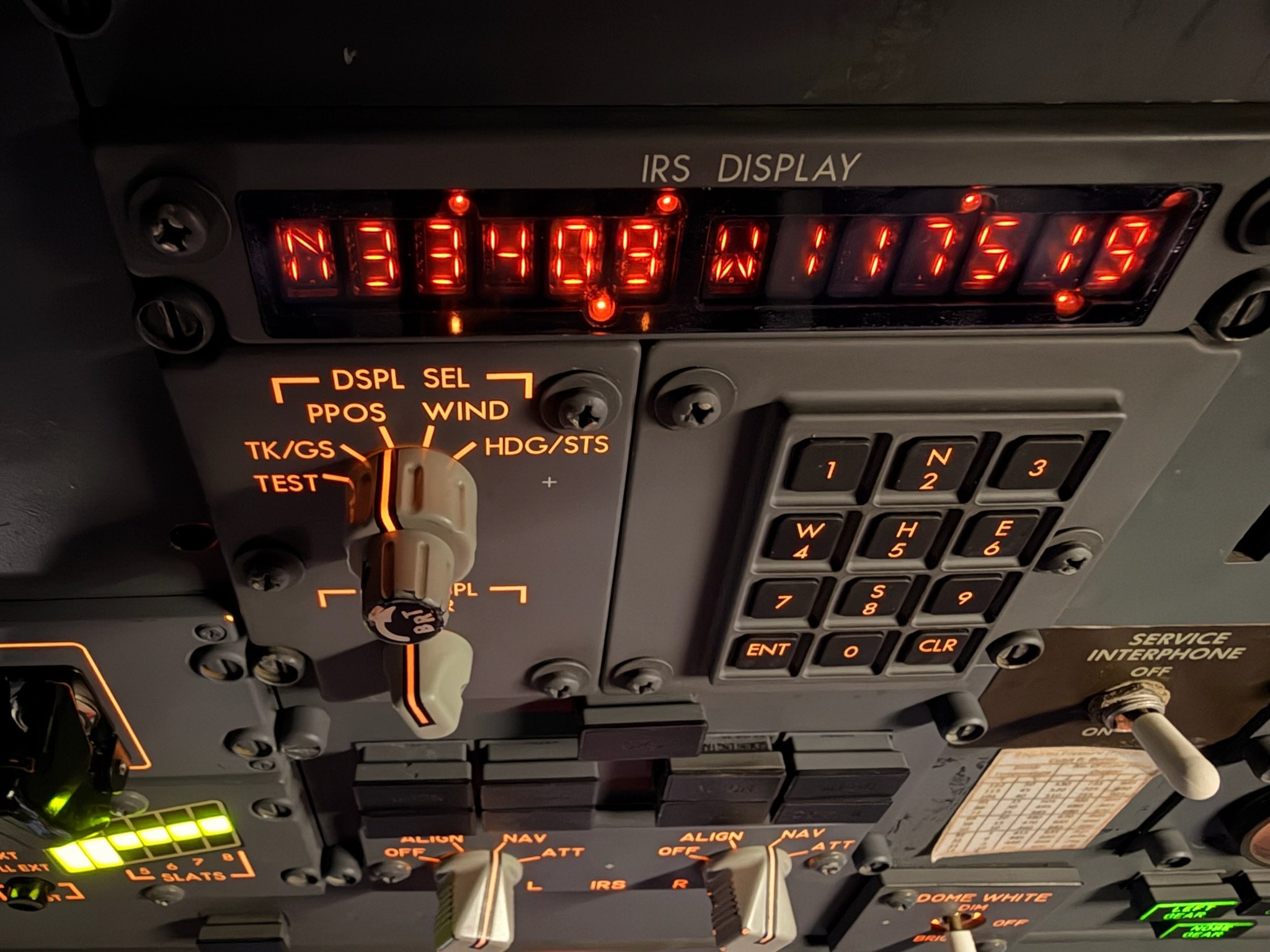
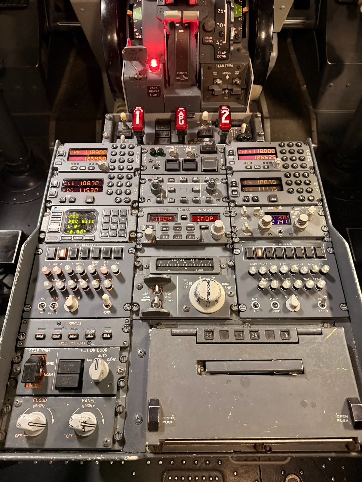
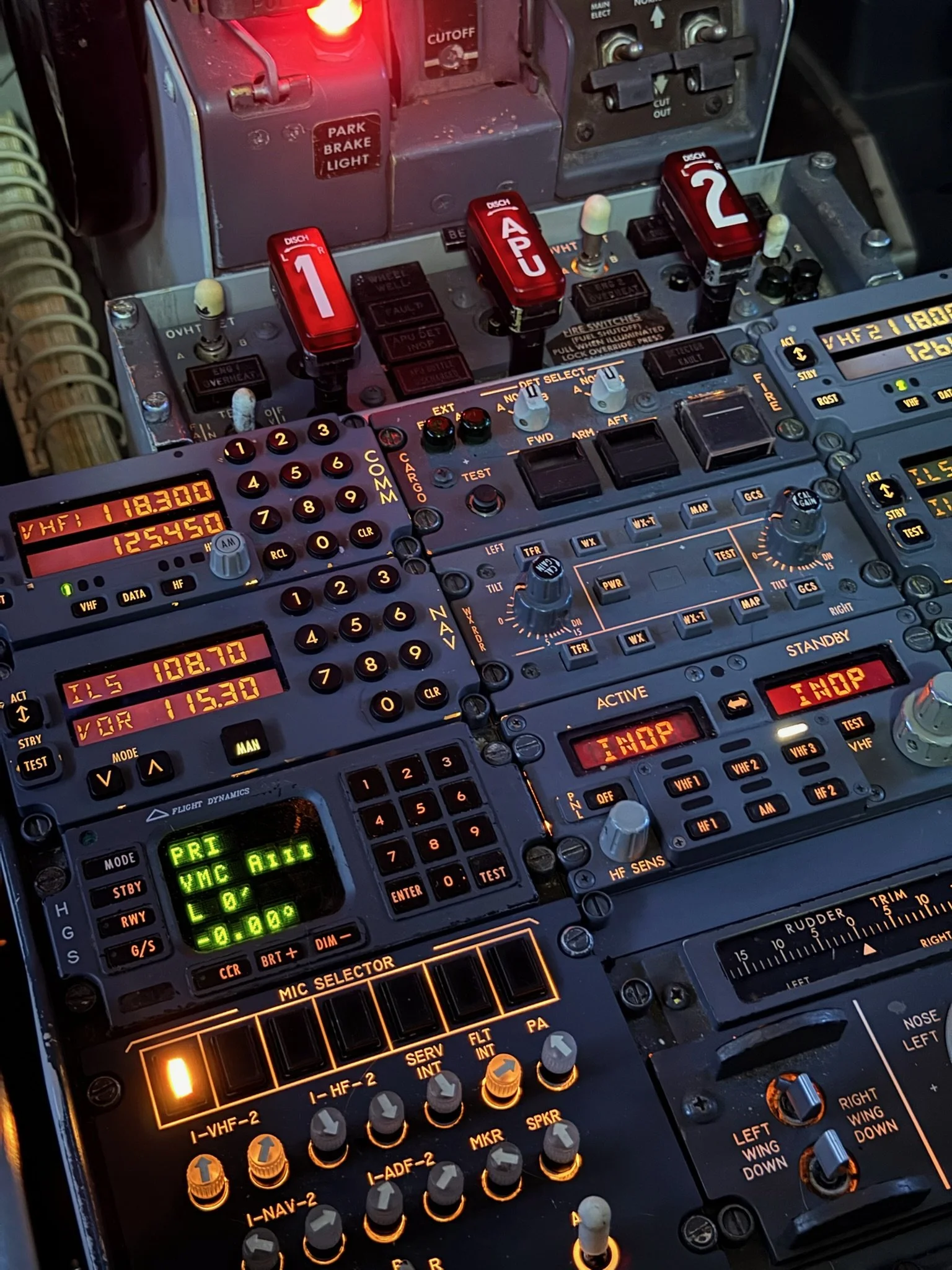
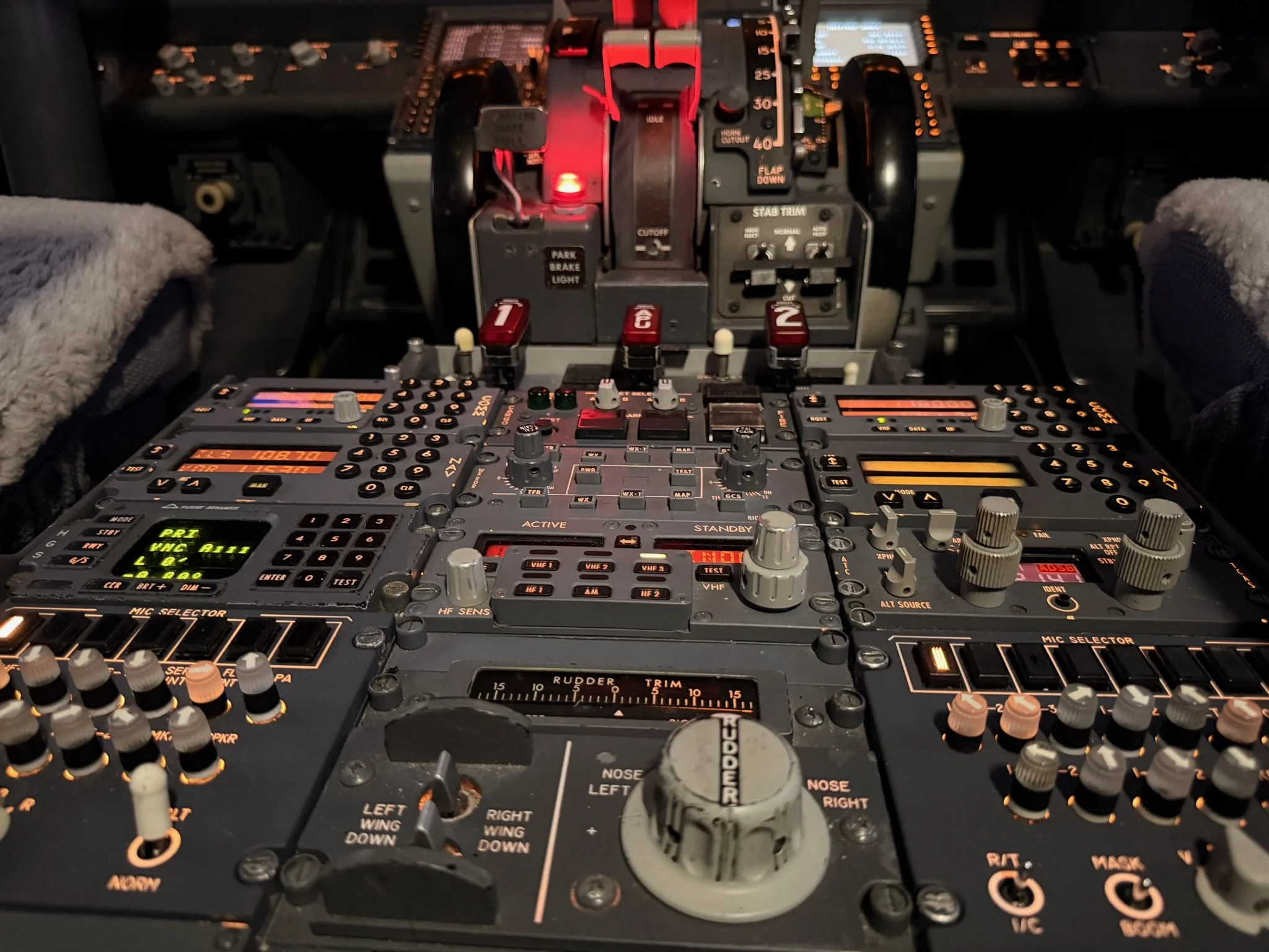
Orange County Sim uses Microsoft Flight Simulator for visuals and environmental modelling, while the ProSim737 avionics suite provides system logic, flight management, automated flight, and cockpit interaction. Nearly every switch, annunciator, and control surface is fully functional. OEM components have been integrated through custom electronics, the ARINC 429 protocol, and dedicated I/O modules, to enable the components to operate exactly as they would have in service.

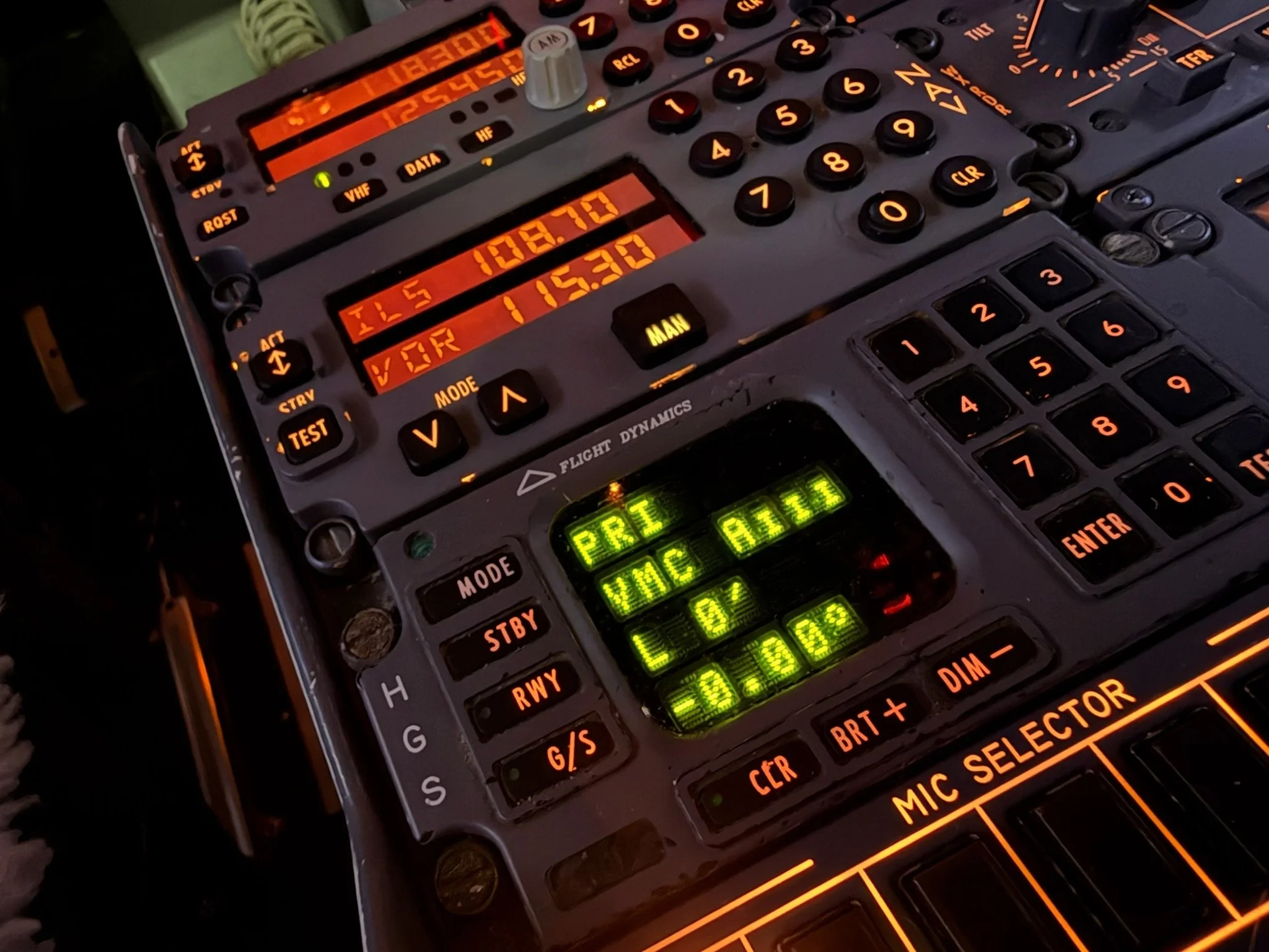
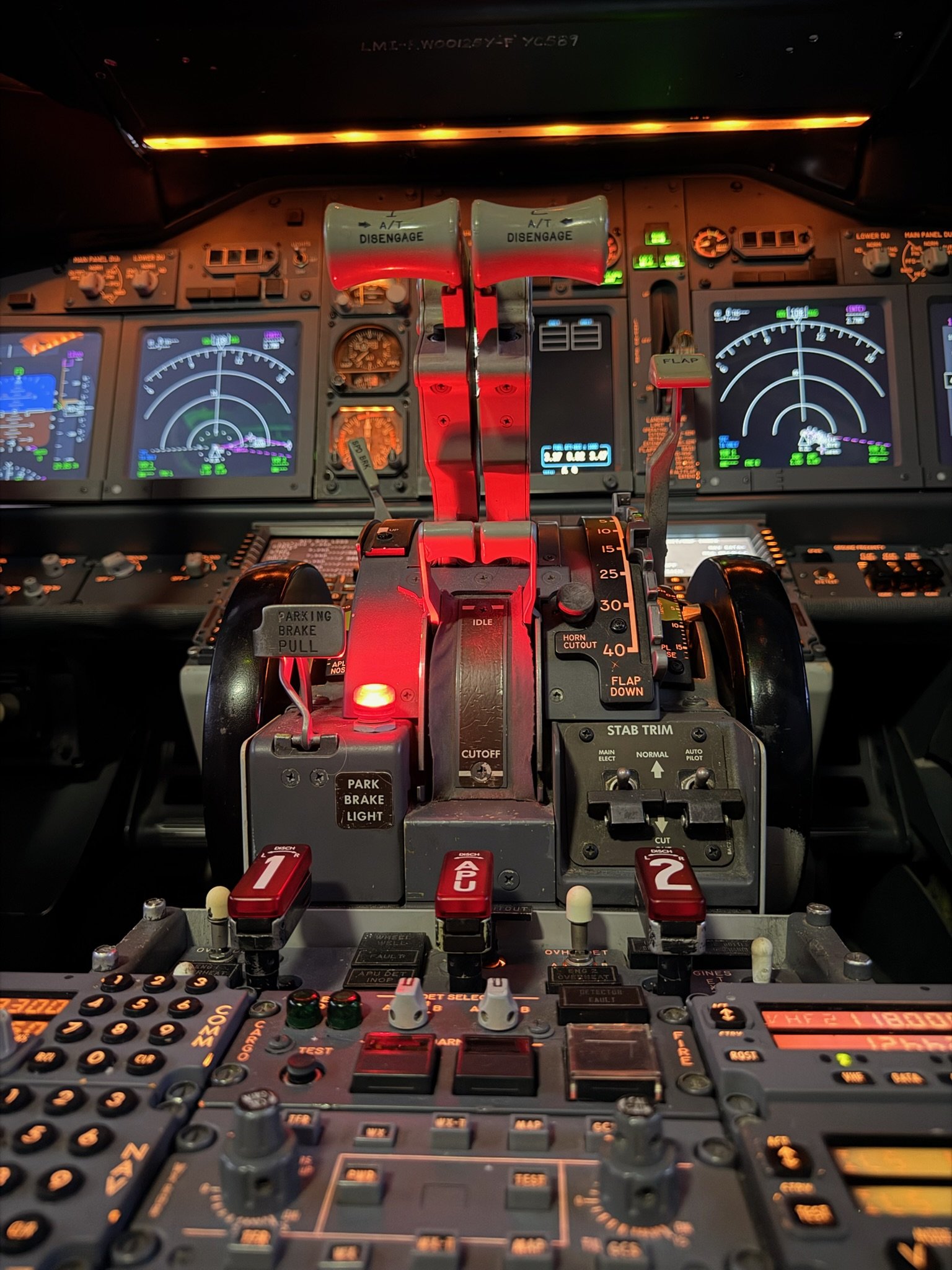
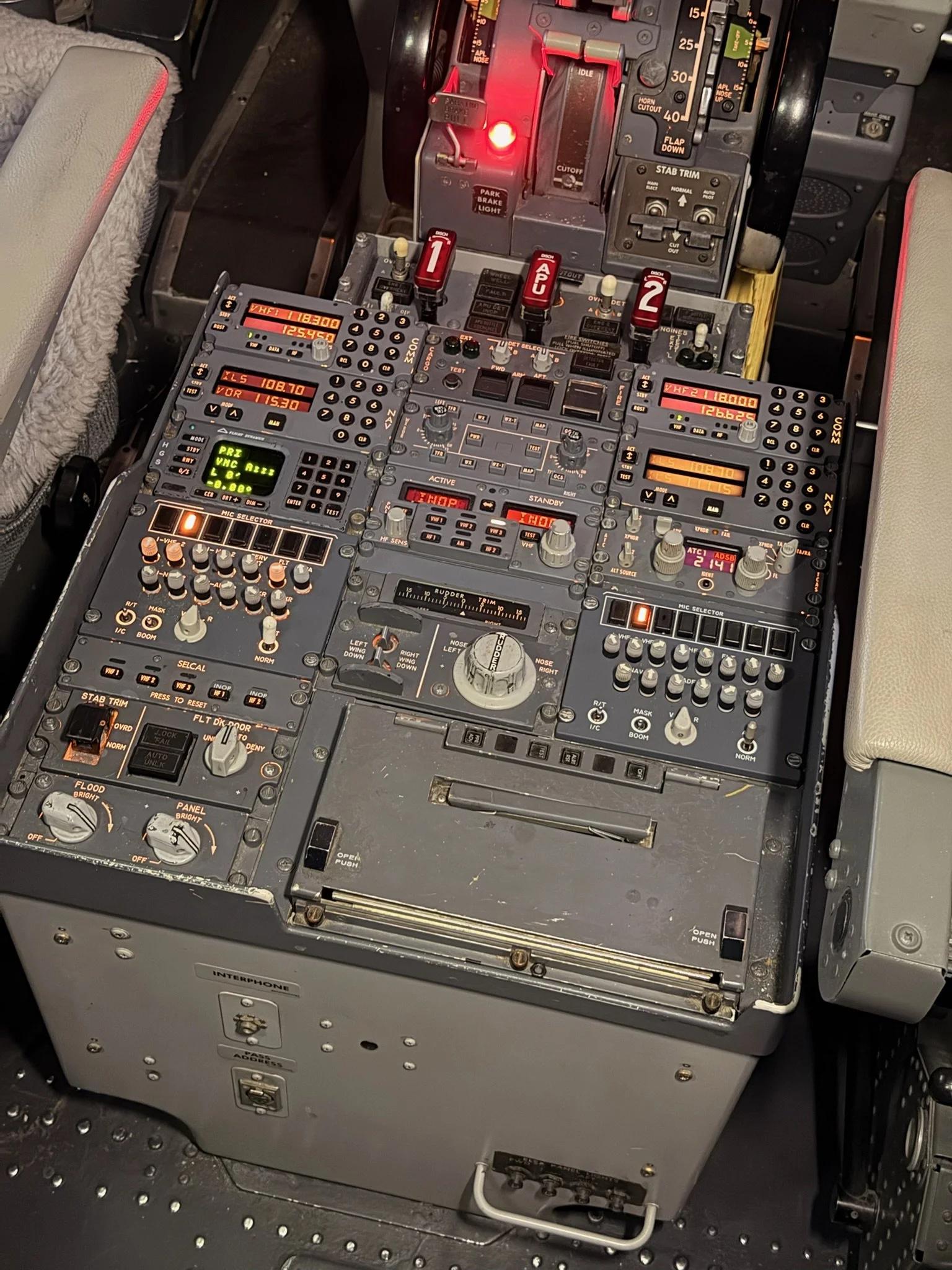
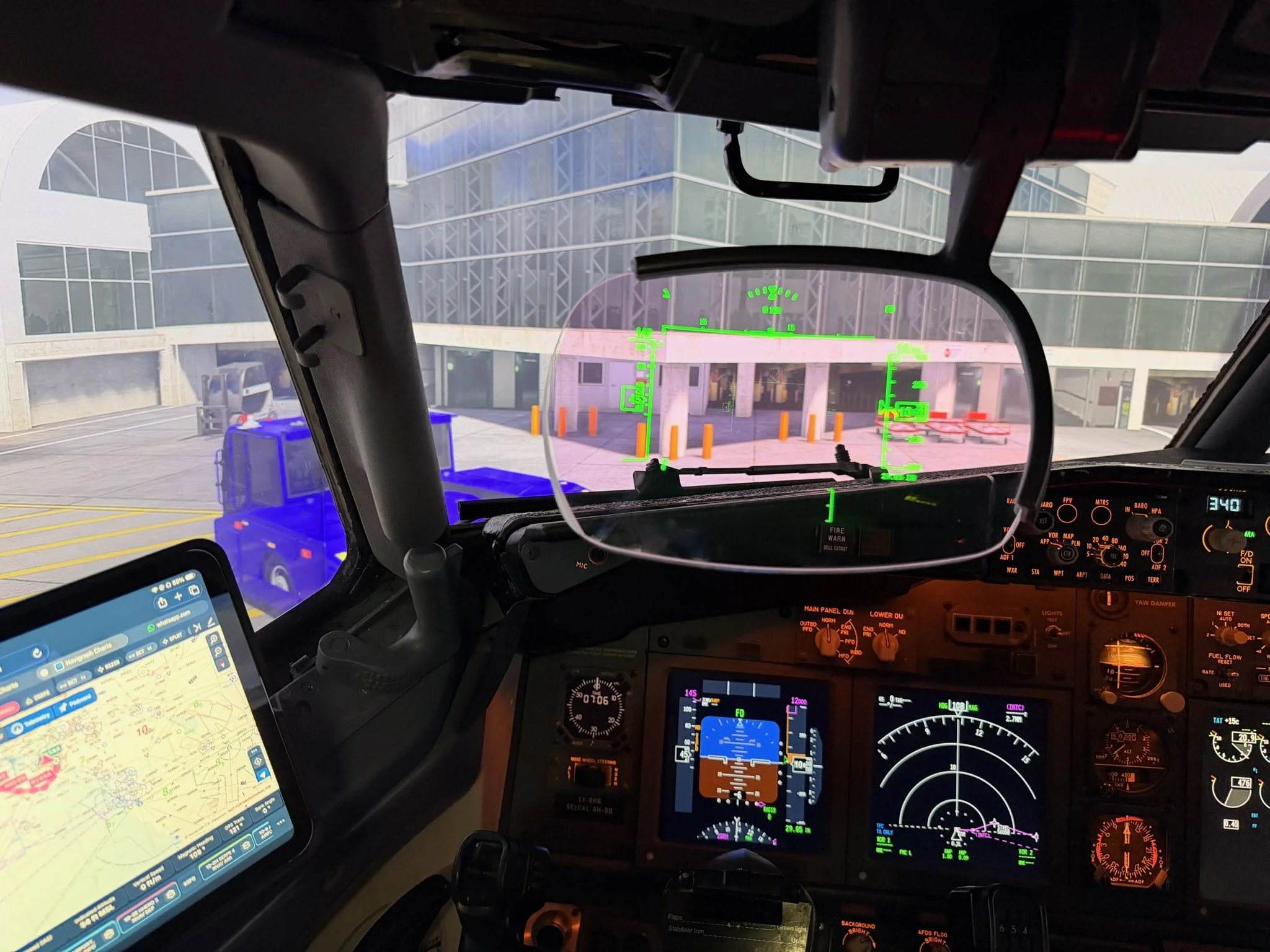
Although many components are standard to an airliner, several features stand out, namely the Heads-Up Display (HUD), the use of OEM EFIS units and navigation radios, the Next Generation 800 series throttle quadrant, and the late model CDU. Enhancing this further is Orange County’s privately developed force‑feedback system, which adds realistic control loading and response to the primary flight controls.

The only major element not implemented is hydraulic motion; otherwise, the simulator functions as a complete, full‑scale 737 flight deck. Its authenticity places it far beyond typical enthusiast builds and brings it remarkably close to the fidelity of a certified commercial training device.

Orange County Sim maintains a website, and it’s well worth exploring - for inspiration, for technical insight, and for a glimpse of what becomes possible when passion, engineering skill, and patience converge.


Orange County 737 Sim


GALLERY: Various photographs of Orange County 737 Sim.


Correct Technique For Extending or Retracting Flaps on the 737-800

I have mentioned the flap extension schedule and procedures before, but because it is important it deserves its own article.

Flaps and airspeed are central to managing the 737‑800’s aerodynamic performance during takeoff, approach, and landing. Deploying flaps increases lift allowing the aircraft to fly safely at lower speeds and creates drag that slows the aircraft’s airspeed. Each flap setting has defined speed limits and associated target speeds that ensure the aircraft remains within structural and aerodynamic boundaries. Maintaining the correct airspeed for the selected flap configuration is important as it supports stable handling, predictable performance, and compliance with certified operating procedures.

In this article the following will be discussed:

  • Flap extension schedule;

  • The maximum flap extension speed;

  • The minimum manoeuvring speed;

  • The upper amber band;

  • The lower amber band;

  • The red and black band; and

  • When to extend or retract the flaps.

Flap Extension Schedule

All too often, novice virtual flyers do not adhere to the flap extension schedule. As a result, extending the flaps at the incorrect airspeed can cause high aircraft attitudes, unnecessary spooling of engines, excessive noise, and increased fuel consumption, which can lead to an unstable approach.

If the flaps are extended at the correct airspeed, the transition will be relatively smooth with minimal engine spooling.

The 737 has 8 flaps positions excluding flaps UP.  It is not necessary to use all of them.  Flight crews will often miss flaps 2 going from flaps 1 to flaps 5. Similarly, flaps 10 may not be extended going from flaps 5 directly to flaps 15 and flaps 25 maybe jumped over selecting flaps 30. Flaps 30 is the norm for most landings with flaps 40 being reserved for short-field landings or when there is minimum landing distance. In the case of using flaps 40, flaps 25 is normally extended.

My preference is to use flaps 25 as it makes the approach slightly more stable. However, if you are conducting a delayed‑flaps approach, selecting flaps 25 may not provide enough time to extend flaps 30 or 40 and complete the landing checklist before dropping below ~1500 feet AGL. Managing this timing is largely a matter of experience.

Flaps 40

The use of flaps 40 should not be underestimated, as aircraft roll out is significantly reduced and better visibility is afforded over the nose of the aircraft (because of a lower nose-up attitude). Because the landing point is more visible, some flight crews regularly use flaps 40 in low visibility approaches (CAT II & III). If the aircraft’s weight is high, the runway is wet, or there is a tailwind, flaps 40 is beneficial. A drawback to using flaps 40, however, is the very slow airspeed, reduced manoeuvrability, and higher thrust required. For this reason, when winds are gusty, it is generally better to use flaps 30.

Advantages – Flaps 40

  • Less roll out;

  • Better visibility over the nose of the aircraft due to lower nose-up attitude;

  • Less wear and tear to brakes as the brakes are generating less heat (faster turn around times);

  • Less chance of a tail strike because of slightly lower nose-up attitude during flare;

  • More latent energy available for reverse thrust (see note); and

  • Helpful when there is a tailwind, runway is wet, or aircraft weight is high.

Disadvantages – Flaps 40

  • Increased fuel consumption (negligible unless flaps 40 are extended some distance from runway);

  • Increased drag equating to increased noise (flaps 40 generates ~10% additional thrust); and

  • Less manoeuvring ability.

NOTE: When the aircraft has flaps 40 extended, the drag is greater requiring a higher %N1 to maintain airspeed. This higher N1 takes longer to spool down when the thrust levers are brought to idle during the flare; this enables a marginally faster reverse response. Therefore, during a flaps 40 landing more energy is available to be directed to reverse thrust, as opposed to a flaps 30 landing.

Flap Retraction Schedule (takeoff)

The technique for retracting flaps after takeoff is similar to the extension sequence described earlier, but performed in reverse. As the aircraft accelerates through each minimum manoeuvring speed reference (explained below), the next flap setting is selected. For example, as the airspeed increases through the flaps 5 manoeuvre speed, select flaps 1; when the airspeed passes the flaps 1 manoeuvre speed, select flaps UP.

Flaps 2 is not used in normal takeoff operations in the 737-800. Flaps 2 is primarily used for:

  • Non‑normal procedures;

  • Abnormal flap asymmetry or failure cases;

  • Certain performance limited or contaminated runway scenarios; and

  • Specific operator SOPs.

If the aircraft’s airspeed is faster than anticipated with flaps extended, care must be taken to ensure it does not encroach into the upper amber band, the significance of which is explained below.

Manoeuvring Speeds

There are four reference displays that are important to understand when extending or retracting the flaps. They are:

  • The minimum manoeuvring speed (Vmin);

  • The amber band;

  • The red and black band; and

  • The maximum flap extension speeds (VFE).

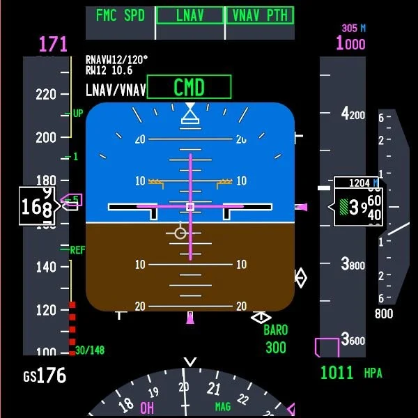
These references are displayed on the speed tape in the Primary Flight Display (PFD).

1: Minimum Manoeuvring Speed (Vmin)

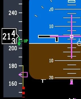
The minimum manoeuvring speed is shown by the green‑coloured numbers on the inner side of the speed tape. For example:

  • Green 1 is the minimum manoeuvring speed for flaps 1;

  • Green 5 is the minimum manoeuvring speed for flaps 5; and

  • Green 10 is the minimum manoeuvring speed for flaps 10.

These numbers represent the minimum safe speed for that flap setting and provide:

  • A stall margin;

  • A manoeuvring margin (~25° bank) 1; and

  • Gust and turbulence protection.

These speeds are computed by the FMC and vary with aircraft weight.

1: Operationally, many airlines teach 25° bank margin, but the certification basis for Vmin actually includes 40° bank capability.

Important Point:

  • At no point should the airspeed decay below Vmin without the appropriate flap setting being extended.

2: Amber Band (two bands - upper and lower)

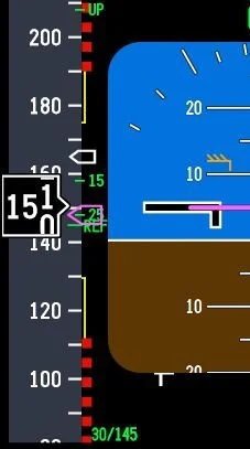
On the Primary Flight Display, the amber bands on the airspeed tape indicate that the aircraft is approaching cautionary speed margins.

  • Upper amber band – approaching maximum operating speed.

  • Lower amber band – approaching minimum manoeuvre speed.

The bands are advisory. They provide a visual indication that the aircraft is approaching a region where the stick shaker, overspeed clacker, or buffet margins could soon be reached. Their visibility depends on the aircraft’s flap configuration and the operational phase of flight, such as takeoff, climb, approach, and landing.

The amber bands are displayed when the aircraft is operating near high or low speed cautionary margins.

Upper Amber Band

The bottom of the upper amber band indicates:

  • The maximum manoeuvring speed;

  • Approach to high speed buffet;

  • The placard speed of the next flap setting (flap retraction); and

  • Indicates when the aircraft is approaching the maximum safe speed for the current flap configuration.

Explained more simply, the upper amber line on the 737‑800 speed tape during descent with flaps extended is the flap overspeed (flap limit) indication. It appears when the aircraft’s airspeed is approaching the maximum allowable speed for the selected flap setting.

In short: The upper amber band warns the pilot they are getting close to exceeding the flap limiting speed for the flap position that is currently have selected.

Lower Amber Band

The top of the lower amber band is the caution / manoeuvre margin and serves as a dynamic, real‑time cue showing the aircraft’s proximity to stall speed. This band represents the zone between the minimum manoeuvre speed and the stall speed awareness band (the red and black band). If the aircraft’s airspeed decays into this band, the aircraft will remain above stall; however, its manoeuvrability (reduced manoeuvring margin) is compromised and the allowable bank angle is reduced.

The top of the lower amber band represents:

  • The top of band indicates minimum manoeuvre speed;

  • The lowest safe speed for the current flap setting (flap extension);

  • Provides 40° bank capability in 1g flight; and

  • Is inhibited on takeoff until first flap retraction or valid VREF entered.

The amber band is not a flap extension reference - it is a stall protection cue and the band must be treated as cautionary. In other words, it is preferable that the aircraft’s speed should not decay to a speed below the top of the amber band.

Loss of bank capability (lower amber band)

When airspeed is at the minimum manoeuvring speed for the selected flap setting, roughly 25° of bank is available without significantly reducing the stall margin. As airspeed decreases into the lower amber band, the safe bank angle typically reduces to about 15°. When approaching the bottom of the amber band, it decreases further to around 5–10°, depending on aircraft weight, turbulence, and other operating conditions.

This is because Increasing bank angle raises the aircraft’s load factor, which in turn increases stall speed.

If the airspeed is already close to the amber band, even a moderate amount of bank can push the aircraft’s airspeed toward the red and black band and stick shaker activation.

Important Point:

  • The Flight Crew Training Manual (Boeing, Flight Crew Training Manual (FCTM) (2024) notes that for operations other than LNAV, when operating at or near maximum altitude, crews should fly at least 10 knots above the lower amber band and limit bank angle to 10° or less. If airspeed drops below the lower amber band, the crew should immediately increase speed by taking one or more corrective actions.

    - Reduce angle of bank;

    - Increase thrust up to maximum continuous; or

    - Descend.

3: Red and Black Band (Vstall)

The red and black-coloured band represents the stall boundary. If the airspeed decays into the red and black band, the aircraft is operating at or near the stall angle of attack. Stick shaker activation will occur when the aircraft’s angle of attack reaches the stall threshold.

4: Maximum Flap Extension Speed (VFE)

The maximum flap extension speed (VFE) for the Boeing 737‑800 defines the highest speed at which each flap setting can be safely selected without risking structural damage. Every flap position has its own VFE limit, and exceeding those limits can stress the flap system. The VFE for the 737-800 are as follows:

  • Flaps 1 → 250 kt

  • Flaps 2 → 250 kt

  • Flaps 5 → 250 kt

  • Flaps 10 → 210 kt

  • Flaps 15 → 200 kt

  • Flaps 25 → 190 kt

  • Flaps 30 → 175 kt

  • Flaps 40 → 162 kt

The VFE speed should be readily visible on a placard attached to the MIP below the landing gear handle.

What this means is that the pilot can extend the flap setting that is adjacent to the maximum speed, however, during normal operations, flight crews rarely extend flaps at VFE. Rather, they typically reduce speed to something closer to the UP speed on the speed tape and then begin to extend the flaps.

When To Extend Flaps

Expanding on what has been written, the flaps should be extended when the airspeed is below the maximum flap extension speed (VFE) and at or above the minimum manoeuvring speed (Vmin).

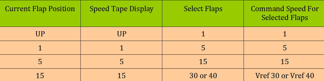
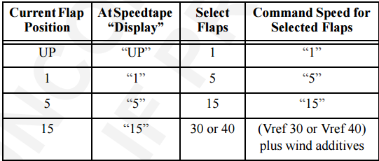
The correct technique is to select the next flap increment as the airspeed passes through the previous flap reference. For example, as the airspeed approaches or passes the flaps UP manoeuvre speed, select flaps 1; when the flaps 1 manoeuvre speed is reached, extend flaps 5.

It’s common practice for pilots to skip flaps 2 and go directly to flaps 5. Similarly, flaps 10 may be excluded (flaps 5 directly to flaps 15). The reason for this is that flaps 2 provides:

  • No operational advantage in normal flying and is mainly there for non‑normal procedures;

  • Abnormal flap conditions; or

  • Specific operator SOPs.

Similarly, flaps 10 provides no operational advantage in the standard approach profile. Flaps 10 is usually only used for:

  • Non‑normal flap operations;

  • Partial flap landings; and

  • Flap asymmetry or failure cases.

This said, in my experience using flaps 10 can offer benefits if ATC request a slow airspeed.

TABLE 1: Flap Extension Table. The table does not include flaps 2, 10 & 25 as these flap settings are often overridden to the next flap setting. © JAL-V

Manoeuvring Speed

Boeing recommend flight profiles should be flown at, or slightly above, the recommended manoeuvre speed for the existing flap configuration. These speeds allow full manoeuvring capability (25° bank). (Boeing, Flight Crew Training Manual (FCTM) (2024).

Important Point:

  • Selection of the flaps to the next flap setting should be made when approaching, and before decelerating below, the manoeuvre speed for the existing flap setting (Boeing, Flight Crew Training Manual (FCTM) (2024).

Speed Trend Vector

When the aircraft’s airspeed is increasing or decreasing a green-coloured upwards or downwards facing arrow is displayed on the speed tape. This is called the speed trend vector. The arrow indicates the predicted airspeed in the next 10 seconds based on the current airspeed and acceleration / deceleration rate.

The speed trend vector can be very helpful in gauging the correct time at which to extend the next increment of flaps.

Flap extension is not instantaneous, and depending on the selected setting, it can take several seconds for the flaps to transition between increments. Because the downward facing trend arrow shows where the airspeed will be in approximately 10 seconds, it can be used as a rough reference for timing the next flap selection. In practice, the next flap increment should be initiated as the trend arrow is close to or at the minimum manoeuvring speed (Vmin) reference 2.

2: This technique is not published by Boeing, but is a useful technique that pilots often use.

Important Points:

  • Correct management of the flaps is selecting the next lower speed as the additional drag of the flaps begins to take effect.   

  • If consideration is made toward when the flaps are extended, the transition between flap increments is relatively smooth.

Final Call

This article has explained the key references used to determine when to extend or retract the flaps. By following the recommended flap extension and retraction speeds and maintaining the correct airspeed, the aircraft remains within its certified limits and each configuration change occurs in a controlled manner. When the procedure is followed as intended, flap transitions remain smooth and the aircraft maintains a stable, well managed approach profile.

BELOW: Images showing the various display references discussed above:

  • The minimum manoeuvring speed (green-coloured numbers);

  • The amber band (upper and lower)

  • The red and black band; and

  • The speed trend vector arrow.

Starting Sequence and Batch File Use for ProSim737 Avionics Suite

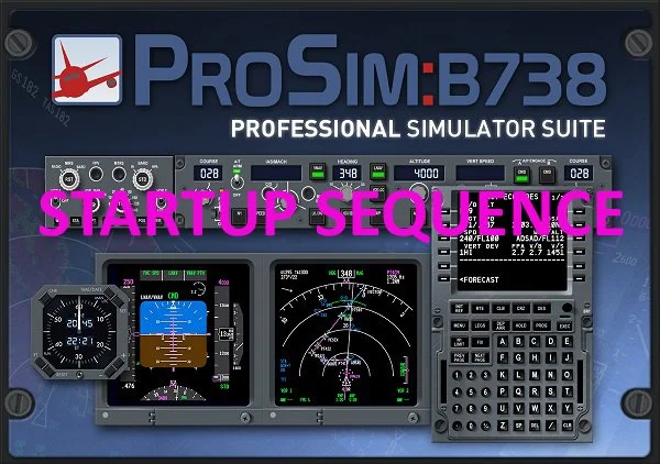
Splash screen - Prosim737 main module (startup sequence added)

Introduction

A full cockpit simulator that emulates Boeing 737 avionics is far more complex than a desktop flight simulator. A full cockpit simulator integrates multiple hardware components, a complete avionics suite, and several layers of ancillary software. Each component, whether responsible for flight controls, cockpit displays, or system logic must communicate reliably with the others to maintain a seamless and accurate simulation environment.

Because the system’s components are interdependent, the software must be started and shut down in a logical sequence to maintain stability, performance, and consistent behaviour. This is especially important when multiple applications are part of the same workflow, as each component may depend on specific services, configuration states, or background tasks being completed prior to initialisation.

This guide outlines the recommended startup sequence for the ProSim737 avionics suite. It also describes the key components involved and introduces batch files as a practical method for automating the process, ensuring that the flight simulator and its supporting software start and shut down in a controlled and predictable sequence.

Terminology Note: In this article, the terms run, launch and start are used interchangeably.

ProSim737 - Module Instances and Configuration

The ProSim737 avionics suite is designed to operate in both single and multi-computer environments. To support this flexibility, the platform allows a variety of system configurations, including running multiple instances of the same module simultaneously. The only exception is the ProSim737 main module, which must be installed on the server computer running Flight Simulator.

This capability allows individual modules to be tailored to specific functions, providing flexibility in how displays, audio, and other systems are configured. For example, a single display module can be started multiple times to serve different cockpit functions. Four instances can provide the Captain’s and First Officer’s Primary Flight Displays (PFD) and Navigation Displays (ND).

The same principle applies to the audio module. Multiple instances can run in parallel, enabling specific sounds, such as callouts, system alerts, or environmental audio, to be routed to different speakers throughout the simulator.

Typical ProSim737 Setup

A typical Flight Simulator setup will run one or more instances of the following ProSim software:

  • ProSim737 main module.

  • ProSim IOS (Instructor Operator Station).

  • ProSim Display module.

  • ProSim Audio module.

  • ProSim Hardware Connector.

  • ProSim CDU.

  • ProSim Overhead (main panel).

  • ProSim Chrono module (clock and timer).

More complex setups may involve both server and client computers, with multiple instances of the same components running across the network. To ensure proper communication between these modules, the ProSim737 main module must be running and active, as it manages all interactions within the ProSim737 avionics suite.

ProSim737 Module Startup and Communication Logic

The most important module in the ProSim737 family is the ProSim737 main module, which serves as the central controller and must be running and initialised before other modules can communicate.

When run, the ProSim737 main module will:

  • Scan the network for other ProSim modules;

  • Establish communication channels (typically via TCP/UDP);

  • Begin sending and receiving data packets; and

  • Activate the other modules, which ‘wake up’ once communication is established (if in standby mode).

If any other ProSim module is opened before the main module, it remains idle; it processes no flight data, performs no system initialisation, and generates no errors - until a connection with the main module is established. Therefore, running modules in standby mode does not harm the software or corrupt any files.

Although ProSim737 is robust and capable of connecting to its sister modules, starting modules in standby mode before the main module can sometimes cause issues. These may include the main module failing to connect to the server, or individual modules not receiving data or functioning correctly.

For this reason, it is recommended to start the ProSim737 main module first. Once it is running, the remaining modules can be opened to ensure a clean connection and a smooth startup process.

If the main module fails to connect, or if an individual module is not functioning correctly, simply close all ProSim modules and restart them. Flight Simulator and other supporting programs can remain running.

Important Point

  • ProSim737 modules can be started in any sequence. However, for the most logical, reliable, and consistent operation, it is recommended to start the main module first, allow it time to initialise, and then start the remaining modules.

When to Start Flight Simulator and ProSim737

For the ProSim737 avionics suite to operate correctly, it is important to follow a logical startup sequence. Begin by starting Flight Simulator, loading a flight, and positioning the aircraft on the runway with the wheel brakes applied to prevent unintended movement. Once Flight Simulator is running correctly, start the ProSim737 main module. After the main module has opened and the software has initialised, the remaining modules can be started.

Launching modules in the wrong sequence will not damage the software, but following a controlled startup sequence ensures each application has time to initialise, establishes clean inter‑module communication, reduces the risk of conflicts, and allows background services to stabilise before use.

Flight Simulator should be started first because ProSim737 relies on several layers of software hierarchy that must communicate with Flight Simulator before the main module can initialise successfully.

Ancillary Software

Although real‑world testing has shown no issues, it is good practice to start any additional software only after Flight Simulator and ProSim737 are running, unless the additional software’s own manual specifies a different startup sequence.

Active Sky

Active Sky (ASFS) is widely used by ProSim737 users because it provides realistic rainfall returns on the weather radar. Hi‑Fi recommends starting Active Sky before launching Flight Simulator so that the desired weather can be viewed and selected prior to loading a flight. However, this is not essential, Active Sky can also be started after Flight Simulator is already running.

Since the ProSim737 main module reads weather information during its startup sequence, it is best to have Active Sky running with the weather already selected (or live weather downloaded and displayed) before starting the main module.

Recommended Starting Sequence

After Flight Simulator and the ProSim737 main module have been started, there is no specific sequence that the remaining modules should be opened. The following is a suggestion:

  1. Flight Simulator.

  2. ProSim737 main module (wait until running and initialised).

  3. ProSim Hardware Connector (if required).

  4. ProSim Display module (Captain and First Officer-side PFD, ND and EICAS - any sequence).

  5. ProSim Audio module (s).

  6. ProSim Chrono module.

  7. ProSim Overhead (main panel).

  8. ProSim other components/displays (if required).

  9. ProSim CDU.

  10. Ancillary Programs.

Note: In this startup sequence, Active Sky (if used) may be started either after Flight Simulator but before starting the ProSim737 main module, or prior to starting Flight Simulator.

Closing ProSim737, Flight Simulator and Ancillary Programs

There is no officially defined shutdown protocol, and depending on your setup, it may be necessary to keep the ProSim737 main module running to use the IOS for closing client computers (For IOS to function, it must maintain a connection with the main module). The following shutdown sequence is therefore recommended:

  1. Close ancillary programs.

  2. Close all ProSim components and displays.

  3. Close ProSim IOS.

  4. Close ProSim737 main module.

  5. Close Flight Simulator.

Batch File Use

Batch files provide an efficient way to automate repetitive tasks within a simulator environment. When configured correctly, they streamline the startup and shutdown of multiple applications, reduce operator workload, and ensure programs run in a controlled, predictable sequence.

This section offers an overview of batch file usage, key concepts, and common syntax relevant to ProSim737 and associated Flight Simulator software.

Function of Batch Files

A batch file is a simple script that executes a series of Windows commands automatically. In a simulation environment, batch files are particularly useful for:

  • Launching, closing, or terminating multiple programs in a defined sequence;

  • Managing timing between application launches;

  • Displaying status messages to the operator; and

  • Reducing manual input and the potential for error.

Batch files can range from very simple (one or two commands) to highly complex scripts containing logic, error handling and console display formatting.

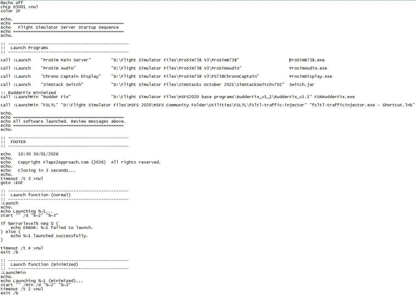
For example, a typical startup batch file used for a simulator session may:

  • Display a formatted header;

  • Launch multiple simulator-related applications;

  • Start programs from specific directories;

  • Display confirmation messages after each command;

  • Insert timed pauses between launches (timeouts);

  • Report success or failure of each operation;

  • Display timestamps or proprietary information; and

  • Automatically close the console window after a defined delay (to allow time to read the console display message).

The batch file may also configure the console display (the pop-up window that appears when it runs) by:

  • Disabling command echoing (@echo off): prevents commands from being displayed;

  • Setting UTF‑8 encoding (chcp 65001): enables support for additional special characters; and

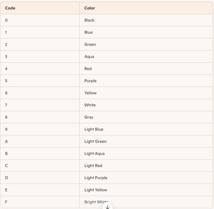
  • Applying custom console colors (color 2F): changes the text and background colors for improved readability.

While the advantages of a startup batch file are clear, a shutdown batch file is equally valuable. Both provide significant time savings and offer a convenient, one‑click method for opening or closing a flight simulator session.

Special Note - Shutting Down Active Sky

Active Sky requires a graceful, timed shutdown. Closing the program without allowing sufficient time can prevent it from shutting down correctly, which may cause it to fail to connect to its server the next time it is started.

If the batch file does not close Active Sky properly, it is recommended to close the program manually. This can be done either by clicking the X in the top-right corner of the window or by right-clicking the Active Sky icon in the Taskbar and selecting Close.

System Stability and Timeouts

Launching multiple programs simultaneously using a batch file can sometimes overload system resources or cause applications to initialise incorrectly, particularly when network connections must be established before proper operation. To prevent this, it is recommended to include a short pause between commands to allow for:

  • Completion of background processes;

  • Graceful initialisation of programs; and

  • Establishment of stable connections for network-dependent modules.

Most ProSim737 modules initialise quickly, and a one-second pause between each module is usually sufficient. However, some modules may require slightly longer delays if additional startup time is needed or if the computer is operating under limited resources. The ProSim737 main module typically takes the longest to initialise; however, a slight overlap during the startup of other modules rarely, if ever, causes issues.

When the main module runs on a server machine and the remaining modules run on a client machine, it should be allowed to fully initialise before starting any client-side modules. This ensures that all dependent components can connect cleanly and helps prevent unnecessary connection errors.

Important Point

  • Timeouts are strongly recommended in startup scripts. During shutdown, they are optional but still beneficial, as programs may require time to save data and close gracefully.

Creating a Batch File

  1. Start Notepad.

  2. Enter the file path and desired batch commands.

  3. Save the file: choose Save As - All Files and apply the .bat extension.

  4. Create a desktop shortcut if desired (the shortcut can also be pinned to the Taskbar).

Note: The batch file can be edited at any time by right-clicking the file and selecting Edit.

Because batch syntax is extensive, the most practical way to learn is to adapt an existing working script. Sample batch files are available for download in the file download section (Batch Files ProSim737 Advanced).

If you search the Internet, you will find several methods to create batch files of varying complexity. Often, there are multiple ways to accomplish the same task.

Important Point

  • Long file paths are easy to mistype. To copy a file path accurately:

  1. Hold Shift and right-click the file; and

  2. Select Copy As Path.

The copied path can then be pasted into Notepad along with the appropriate batch command.

Common Batch Commands

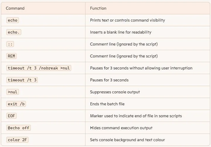
There are many batch commands that can be used. Table 1 outlines some of the more common commands used.

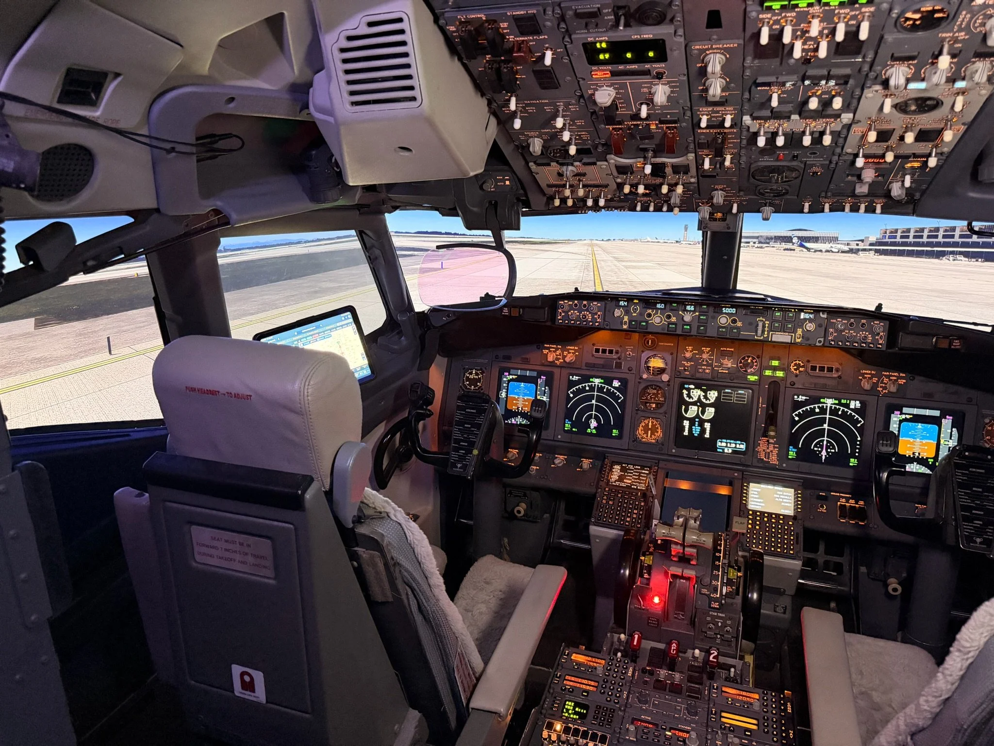
TABLE 1: Common batch file commands

My Preferences

I do not use a batch file to start Flight Simulator (MSFS 2020/2024) or Active Sky.

Flight Simulator can take considerable time to load, depending on connection speeds, and it is important that the software starts gracefully without competing processes. I manually start Active Sky from a taskbar shortcut after Flight Simulator is running and the aircraft is stable at the selected airport.

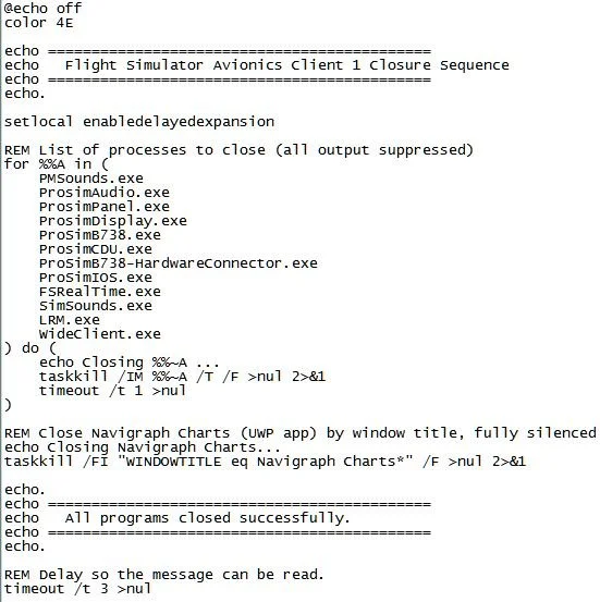
I do use batch files to start the ProSim737 main module and other ProSim components on both server and client computers. A corresponding closure batch file shuts down all programs on the server and client machines.

Sample Batch Files

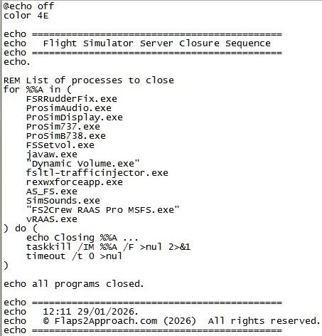
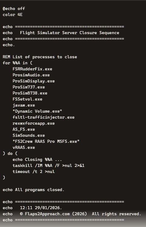
In the sample closure batch file (see the gallery and download section), several programs are listed; some which may not be running when the batch file is executed. This is intentional, as different programs are often used during testing. In practice, executing a batch file that attempts to close programs not currently running has no effect - Windows simply ignores the command without causing any issues.
Troubleshooting Starting Sequence and Batch File Issues

Startup problems with ProSim737 are most often caused by connection issues between the ProSim737 main module and its associated modules. If errors occur during startup:

  1. Allow sufficient time for the ProSim737 main module to start and initialise. Ensure the module connects to the server and fully initialises before starting any other modules.

  2. If problems persist, especially after installing an update, the recommended approach is to:

  • Uninstall ProSim737 and reinstall the latest full (non-beta) release (including modules).

  • After confirming that version works correctly, you may then update to the latest beta if desired.
Important Point

Many startup problems can also related to batch files, particularly if you are unfamiliar with their syntax or directory paths. If a batch file does not function as expected, check that:
  • All directory paths are correct;

  • Commands are typed accurately; and

  • Appropriate delays (timeouts) are included between module launches (if required).

Additional Information

Final Call

Starting ProSim737 modules in the wrong sequence will not damage the software, but following a logical startup sequence and allowing each application time to initialise helps the system establish clean, reliable communication between modules - particularly the ProSim737 main module. By following this controlled startup approach, the likelihood of conflicts is reduced, background services have time to stabilise, and the environment for running Flight Simulator becomes more stable.

To help maintain this stable environment, batch files automate the sequence: they start and close each program in a consistent, methodical sequence, reinforcing the clean startup conditions the system relies on for stable inter‑module communication.

Gallery

Screenshots of batch file examples, batch file syntax colour table and common batch syntax commands.

Disconnecting the Autothrottle and Autopilot (Normal and Non-Normal Operations)

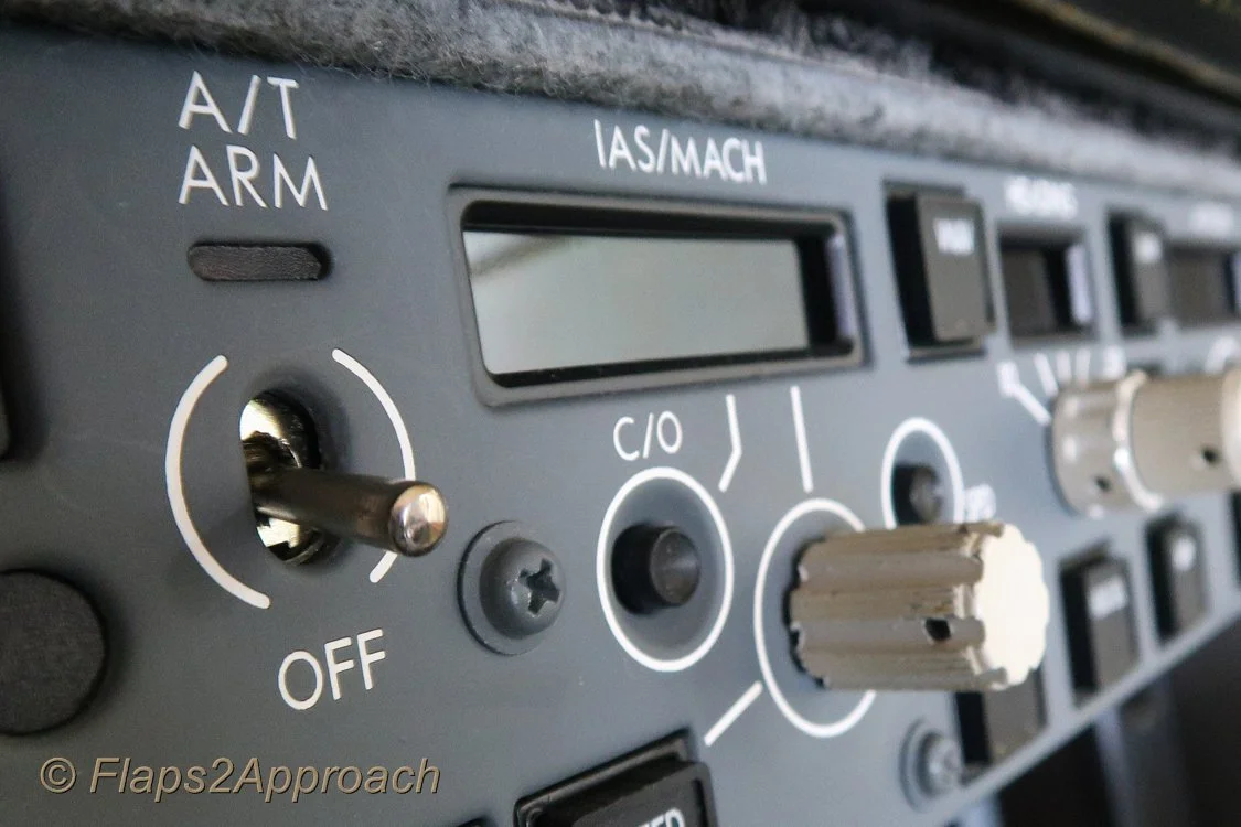
Mode Control Panel (MCP) showing A/T toggle and speed window

This article will examine the use of the autothrottle during normal operations and explore several non-normal conditions, highlighting both the advantages and potential drawbacks. It will also discuss the relationship between the autopilot and autothrottle, offering insight into why the recommended procedure is to operate them in unison, rather than using one without the other.

Note that single engine operation will not be addressed as this is a separate subject.

A search on aviation forums will uncover a plethora of comments concerning the use of the autothrottle which, combined with the use of the autopilot and non-normal procedures, can easily be misconstrued. An interesting discussion can be read on PPRuNe forum.

What is the Autothrottle

The Autothrottle (A/T) is a part of the Automatic Flight System (AFS) comprising the Autopilot Flight Director System (AFDS) and the flight management computer. The autothrottle provides automatic thrust control through all phases of flight and its functionality is designed to operate in unison with the Autopilot (A/P).

Autothrottle Use

The autothrottle is armed whenever the A/T toggle is set to the UP and latched position and the green-coloured annunciator is illuminated on the Mode Control Panel (MCP). The autothrottle is engaged when either the N1 or SPEED button annunciator is illuminated.

The autothrottle is usually engaged during the takeoff roll by pressing one or both TOGA buttons located under the thrust handles. TOGA, sometimes referenced as TO/GA (note diagonal line) is an abbreviation for Takeoff/Go-Around.

Stabilisation Criteria (during takeoff roll)

Allowing the engines to stabilise during the takeoff roll is important, as stabilisation prevents thrust asymmetry whereby one engine may spool at a slower rate during the commencement of takeoff thrust.

%N1 and %N2

TOGA is selected when %N1 readings stabilise for both engines (both arcs matched) at around 40%N1, and when the EGT numbers decrease slightly, typically after 2-3 seconds. Although %N1 (fan speed) is the primary reference for takeoff thrust monitoring, %N2 (core speed) which stabilises earlier at around 20-25% can also be monitored - but bear in mind %N2 is not the key metric.

The reason the autothrottle is used during takeoff, is to simplify thrust procedures during a busy segment of the flight and to ensure that both engines are generating similar thrust.

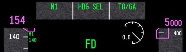
FMA Captain-side PFD showing n1 and TOGA annunciation during takeoff roll. A green coloured display indicates that a particular mode is active - green for go or green is live

Once engaged, the TOGA command mode will control the thrust outputs to the engines until the mode is exited, either at the designated altitude set on the MCP, or by activating another automaton mode such as Level Change (LVL CHG).

When TOGA is engaged, the Flight Mode Annunciator (FMA) will display N1 and TOGA. The FMA display indicates to the flight crew what the AFS is doing.

Important Point:

  • Always monitor the FMA to know what mode is selected and whether the mode is armed or engaged. The monitoring of the FMA cannot be understated.

The Autothrottle is Designed to be Coupled with the Autopilot

The autothrottle is a sophisticated automated system that will continually update thrust based on minor pitch and attitude changes and operates exceptionally well when coupled with the autopilot. But when the autopilot is not selected and the autothrottle is selected by itself, its reliability can be questionable.

Some individuals believe that during a landing with the autopilot off and the autothrottle engaged, a drop in airspeed, such as during the flare, will cause the autothrottle to apply thrust. While this is technically true, there is a lag between the initiation of the thrust command and the engines spooling to the commanded %N1. As a result, there is a risk of a tail strike as the aircraft’s pitch increases before the engines have produced the required thrust. Likewise, excessive wind gusts during the approach can lead to pitch coupling (discussed below).

The advantages of using the autothrottle and autopilot together (coupled) are:

  • Speed is stabilised;

  • Speed floor protection is maintained;

  • Task loading is reduced; and,

  • Flight crews can concentrate on visual manoeuvring and not have to be overly concerned with wind additives.

The disadvantages of using the autothrottle with the autopilot not selected are:

  • Additional crew workload and possible loss of situational awareness (due to workload);

  • Potential excessive and unexpected throttle movement caused by pitch and attitude changes;

  • Potential excessive airspeed when landing in windy conditions with gusts;

  • The potential for pitch coupling to occur (discussed below); and,

  • A loss of thrust awareness (out of the loop).

Important Point:

  • The autopilot and autothrottle should not be used independently of each another.

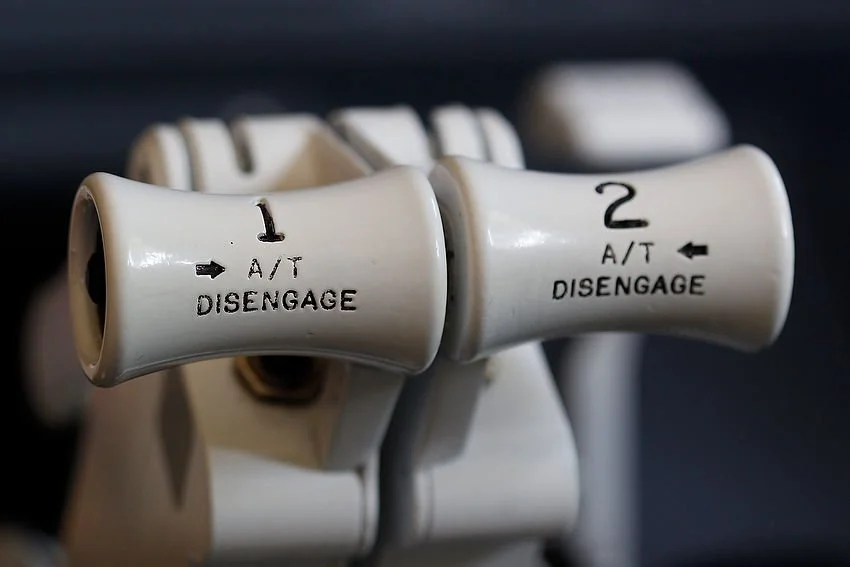
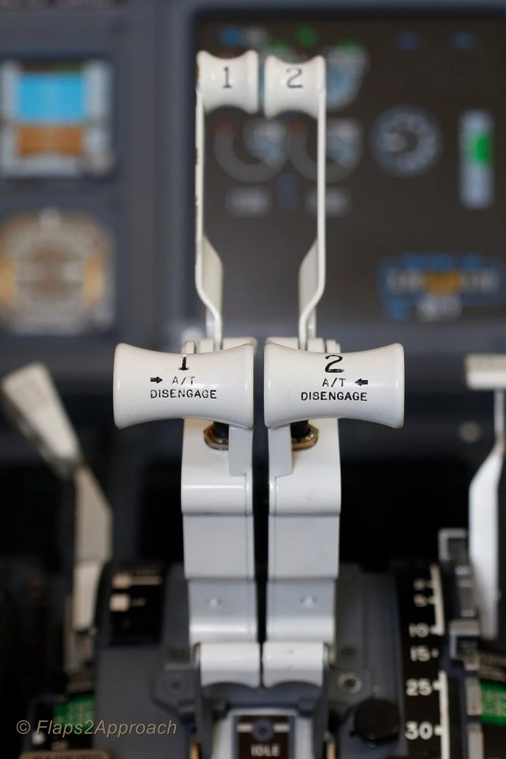
737 Next Generation thrust levers. TOGA and A/T disconnect buttons are just visible

Pitch Coupling

Pitch coupling occurs when the autothrottle system actively attempts to maintain thrust based on the aircraft’s pitch or attitude. It can occur when the autopilot is disconnected while the autothrottle remains engaged. In this situation, the pilot uses manual pitch and roll inputs to control the aircraft, while the autothrottle controls the thrust output.

The design of the 737 airframe is prone to pitch coupling because of its under wing mounted engines. The position of the engines cause the thrust vector to pitch upwards with increasing thrust and pitch down with a reduction in thrust.

When the autopilot is disconnected and the autothrottle is engaged, the pilot controls pitch manually while the autothrottle adjusts thrust to maintain airspeed. Because thrust changes influence pitch and pitch changes affect airspeed, the two systems can interact with each other. This coupling of pitch and thrust can create a roller‑coaster effect as the aircraft alternately increases and decreases pitch in response to pilot inputs and autothrottle driven thrust changes.

This coupling of pitch to thrust can be potentially hazardous; namely:

  1. When flying an approach due to the lower above ground altitude and airspeed (closer to Vref); and,

  2. In windy conditions whereby; the autothrottle will command the engine to spool up and down based on wind speed and gusts.

The autopilot and autothrottle have been designed to operate in unison, and the autopilot’s high level of fidelity can compensate for any variations in pitch and thrust output, as well as the inherent lag between commanded N1 settings and engine spool‑up.

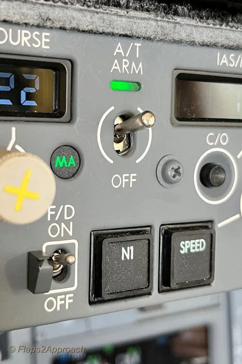
A/T ARM toggle, N1 and speed button.  The N1 and speed button illuminate when either is in active mode.  In the image, the A/T is armed; however, the speed option is not selected (the annunciator is extinguished).  This enables thrust to be controlled manually

Autothrottle Non-Normal Operations (Arm Mode)

The primary function of the A/T ARM mode is to provide minimum speed protection.

The autothrottle system comprises two discrete functions - the A/T ARM toggle and the SPEED button, which operate either in combination or independently of each other. Both functions are accessed from the MCP.

During normal operations, the A/T ARM toggle is positioned in the UP position and the function of the SPEED button is coupled to the toggle. When selected, both functions display green-coloured lights on the MCP and the speed window displays the target speed.

During non-normal operations, the A/T ARM toggle and the SPEED button do not operate as a coupled system. To decouple the two functions, the SPEED button is pressed to disconnect the speed function. When disconnected, the green-coloured light will be extinguished and the speed window will be blank with no target speed displayed. This will place the autothrottle in the ARM mode.

When using the autothrottle in ARM mode, it is important to monitor the FMA to determine whether the autothrottle is armed or engaged. It is not prudent to rely solely on the green lights on the MCP, as these indications confirm only that a mode has been selected, not that it is actively engaged or performing as expected.

When in ARM mode, the FMA displays the word ARM in white letters within an outlined white box. Conversely, when the SPEED button is pressed (to engage speed mode), the colour of ARM changes from white (armed) to green (engaged).

Note that the outlined box on the FMA is initially displayed in white (armed/pre‑selected) to indicate that a mode change has been commanded. The box then changes to green (engaged) after approximately 10 seconds to signify the active mode.

Why Use ARM Mode

The primary purpose of decoupling speed from the autothrottle is to permit manual thrust control while retaining the autothrottle in the armed state. This can be advantageous during non-precision approaches. Recall that the autopilot and autothrottle must not remain engaged during the final stages of the approach and landing, except during an autoland.

The arming of the autothrottle is an expedient way to engage the autothrottle if a Go-Around is required - all that is required is to push the TOGA buttons on the thrust lever and the autothrottle will engage (rather than having to manually engage the autothrottle). This enables a Go-Around to be executed more expediently and with less workload.

If the approach proceeds smoothly and a go‑around is not required, the crew will, prior to landing, disengage the A/T toggle on the MCP by either manually moving the toggle to the OFF position or pressing the A/T buttons on the thrust levers. If the A/T toggle is not placed in the OFF position, the autothrottle system will automatically disconnect when the main wheels touch down, based on WOW logic (Weight‑on‑Wheels logic is triggered by the squat switches on the main landing gear, which activate when the shock strut is compressed by a predefined amount).

Although this procedure is favoured by some flight crews, this practice is not authorised by all airlines, with some company policies expressly forbidding the ARM A/T technique.

FMA display showing the relationship between the A/T toggle and the Speed button

The reason this procedure is prohibited by some airlines is the variety of approach types the 737 can fly. Crews accustomed to precision approaches, where this technique is unnecessary, may become uncertain about the autothrottle’s behaviour, and there have been several incidents in which crews failed to notice significant airspeed changes.

The recommendation by Boeing in the 737 Flight Crew Training Manual (FCTM) states:

‘The A/T ARM mode is not normally recommended because its function can be confusing. The primary feature the A/T ARM mode provides is minimum speed protection in the event the airplane slows to minimum manoeuvring speed. Other features normally associated with the A/T, such as gust protection, are not provided’. (When the A/T is armed and the SPEED button not selected).

Important Points:

  • It is important that, if the autothrottle is disconnected or in ARM mode, the crew maintains vigilant monitoring of the aircraft’s airspeed.

  • The ARM mode is not suitable for all approach types and usually is only used for non-precision approaches.

Speed Protection (Windy, Gusty and Turbulent Conditions)

The autothrottle system provides speed protection through airspeed and acceleration sensing; however, its effectiveness depends on correct use of wind additives and an understanding of how the system behaves in gusty or turbulent environments.

To ensure adequate wind and gust protection when using the autothrottle during an approach in windy conditions, the command speed should be set to the appropriate wind additive. This additive is derived from the prevailing wind speed, direction, and gusts, and typically ranges between Vref +5 and Vref +20. Applying a wind additive provides a safety buffer that accounts for fluctuations in wind velocity and reduces the likelihood of the autothrottle commanding a speed that drops below Vref.

In turbulent conditions, the autothrottle maintains a thrust level that averages higher than the minimum required in order to preserve the commanded approach speed.

When to Apply Additives to Vref

Although the concept is comparatively straightforward, there is often uncertainty about the appropriate speed additives to apply to Vref, particularly regarding whether the autothrottle is in use. To clarify the process:

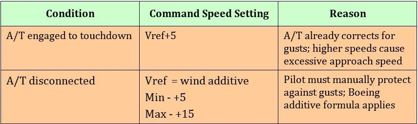
  • If the autothrottle is to be engaged for landing (for example autoland), set the command speed to Vref+5. There is no need to add wind additives as the autothrottle logic already compensates for gusts through airspeed and acceleration sensing.

  • If the autothrottle will be disconnected (or not selected) for landing, set the command speed to Vref plus the appropriate wind additive to account for steady wind and gusts. This will ensure that speed protection is provided.

Table 1: Summary of A/T conditions, speed settings and reasons


Important Point:

  • Minimum speed protection is lost when the autothrottle is not engaged, or the SPEED function on the MCP is deselected.

Additional Information

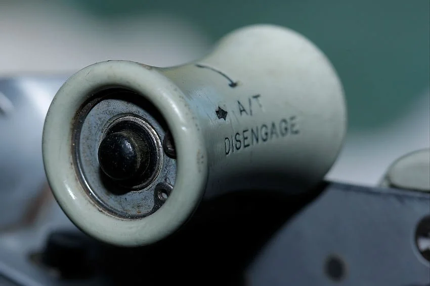
A/T disengage button on throttle thrust lever (Captain-side).  This is an OEM throttle from a 737-300 series (classic).  The button is identical to that used in the NG with the exception that the thrust handles are usually white and not grey in colour.  Depressing this button will disconnect the autothrottle

Manual Override - Engaging the Clutch Assembly

Occasionally, for any number of reasons, the flight crew may need to override the autothrottle.

The Boeing autothrottle system incorporates a clutch mechanism that allows the flight crew to manually advance or retard the thrust levers while the autothrottle remains engaged. When the thrust levers are moved, the clutch automatically disengages the servo drive, placing the autothrottle in an overridden state for the duration of the manual input.

This clutch arrangement provides the capability for immediate manual thrust intervention, whether for abnormal situations, rapid thrust changes, or any circumstance requiring direct pilot control.

Correct Sequence for Disconnecting the Autopilot and Autothrottle

There is considerable confusion as to when to disconnect the autothrottle and autopilot and in what order.

Whenever hand flying the aircraft, the autopilot and autothrottle must not be engaged. If they are engaged they both should be engaged, but which do you disengage first - autopilot or autothrottle. Best practice is to always disconnect the autothrottle before the autopilot. The reason being is that the aircraft ‘s autothrottle system has a slightly faster response time than the autopilot (the last thing you need is for the autothrottle to spool up after disconnecting the autopilot). Disconnecting both systems enables the pilot to have full manually control of the aircraft. Furthermore, do not disconnect both in rapid fire - take your time and wait a second between disconnecting the autothrottle followed by the autopilot. This enables a more seamless transition to occur.

To disconnect the autopilot and silence the autopilot disconnection horn:

  1. Press the deselect button on the yoke - one click to disconnect the autopilot and a second click to silence the autopilot disconnection horn;

  2. Press the CMD button on the MCP or;

  3. Lower the disconnect bar on the MCP.

To disconnect the autothrottle:

  1. Press the autothrottle disconnect buttons on the thrust levers; or

  2. Move the A/T ARM switch on the MCP to the OFF position.

To extinguish the flashing autothrottle and autopilot annunciators on the AFDS either:

  1. Press each of the AFDS annunciators that are flashing to extinguish the lights; or

  2. Press the deselect button on the yoke and autothrottle disconnect buttons on the thrust levers.

Timing of Disconnect (four-click sequence)

Whilst disconnecting both the autopilot and autothrottle simultaneously is perfectly acceptable, it is generally preferable to do so in a controlled sequence. It is a four-click sequence.

  • One click of the throttle disconnect buttons disengages the autothrottle. A second click cancels the warning.

  • One click of the deselect button on the yoke disconnects the autopilot, a second click silences the aural alert.

Whether this makes a measurable difference is difficult to quantify, but a calm, deliberate disconnection sequence, with a slight pause between clicks, appears far more controlled and elegant than rapidly clicking multiple times in quick succession.

At What Altitude Should the Autothrottle be Disconnected

A common preference amongst flight crews, when flying a non-precision approach, is to disconnect the autopilot and autothrottle no later than 1500 feet AGL. This is the altitude at which the aircraft should be fully configured for landing, with landing checks completed, the landing gear down, flaps set to 30, and the aircraft established within the required vertical and lateral tolerances.

That said, the altitude is not fixed unless specified by airline policy. A useful maxim is to use the Decision Height (DH) or Minimum Descent Altitude (MDA) as the point at which to disconnect the autothrottle.

Disconnecting the autopilot and autothrottle earlier in the approach provides additional time to transition from automated to manual flight and to establish a feel for the aircraft before landing.

Many flight crews, particularly experienced pilots confident in manual flying, regularly choose to hand‑fly the aircraft. Some will fly from 10,000 feet to landing using the FD, ILS, VNAV, and LNAV cues on the PFD, supported by the ND for situational awareness. Hand‑flying the approach is widely enjoyed, even though it remains one of the most demanding phases of flight.

Important Point:

  • Whenever the aircraft is being hand‑flown with the autothrottle disconnected, it is essential to closely monitor airspeed. This is particularly critical on final approach, where thrust can decay quickly and bring the aircraft close to stall speed.

Hand Flying Without Automation

The benefit of flying with the autopilot and autothrottle disconnected is the ease with which the aircraft can be manoeuvred. The crew sets the appropriate %N1 to produce the thrust required to maintain the desired airspeed; gone are the thrust surges that occur as the autothrottle attempts to maintain speed. This technique is often referred to as ‘flying by the numbers’.

Granted, it takes considerable time and patience to become proficient at manual flying in a variety of conditions, but the overall enjoyment increases significantly.

Company Policies

Airline policies often dictate how a flight crew will operate an aircraft, and while some policies are expedient, they are more often based on economic considerations for the company.

Policies vary with respect to autothrottle use. For example, Ryanair, Air New Zealand, and Kenya Airways require the autopilot and autothrottle to be disconnected simultaneously. QANTAS follows a similar approach; however, they specify an altitude by which disconnection must occur (1500 feet AGL) and stipulate that the autothrottle is to be disconnected before the autopilot, with a distinct pause between each disconnection.

If an airline does not publish a policy, the decision is left to the discretion of the flight crew.

Simulator Nuances

The above information primarily discusses the systems as they operate in the real aircraft. Whether these systems are functional in a simulation depends on the avionics suite in use (Sim‑Avionics, Project Magenta, ProSim737, etc.).

For example, the autothrottle may not maintain the speed selected on the MCP under certain conditions, such as during turns in high winds. In the real aircraft, the crew would manually override the autothrottle. However, if the throttle hardware or avionics suite does not support manual override, the next best option is to either:

  • Disconnect the autothrottle and manually adjust thrust; or

  • Press the SPEED button on the MCP to place the autothrottle in ARM mode, allowing manual control of thrust. Once the manoeuvre is complete, the autothrottle can be re‑engaged by pressing the SPEED button again.

If your throttle does not support manual override, or the avionics suite does not model this functionality, the second option is an effective way to compensate for the limitation.

Final Call

There is little argument that the use of the autothrottle is a major benefit in reducing task loading; however, as with other automated systems, this benefit can come at a cost. This has led several airlines to introduce policies prohibiting the use of the autothrottle without the autopilot. Pitch coupling, excessive vertical speed, and incorrect thrust settings can all contribute to hard landings, possible nose‑wheel collapse, undesirable ground‑effect behaviour, or even controlled flight into terrain.

Ultimately, the decision to use the autopilot and autothrottle as a coupled system rests with the pilot in command and depends on crew experience, environmental conditions, and airline policy. However, Boeing’s recommendation is to avoid using the autothrottle without the autopilot engaged.

Additional Information:

Acronyms and Glossary

  • A/P – Autopilot.

  • A/T – Autothrottle.

  • AFDS – Autopilot Flight Director System
.

  • Command Speed - the target airspeed that the autothrottle (A/T) is trying to maintain.

  • FCTM – Flight Crew Training Manual (Boeing Corporation).

  • FMA – Flight Mode Annunciator.

  • Manual Flight – Hand flying aircraft. A/P and A/T disconnected.

  • MCP – Mode Control Panel.

  • Minimal Speed Protection – Function of the A/T when engaged. The A/T has a reversion mode which will activate according to the condition causing the reversion (placard limit). (For example, flaps, gear, etc).

  • Pitch Coupling – The coupling of A/T thrust to the pitch of the aircraft. A/T thrust increases/decreases as aircraft pitch and attitude changes. Pitch coupling occurs when the A/P is disconnected, but the A/T is engaged.

  • Selected/Designated Speed – The speed that is set in the speed window of the MCP.

  • SPEED button – Located on the MCP the SPEED button (when not illuminated) disconnects the speed from the autothrottle system whilst keeping the autothrottle in the armed mode.

  • Take Off/Go Around (TOGA) – Takeoff Go-around command mode. This mode is selected during takeoff roll by depressing one of two TOGA buttons beneath the throttle levers.

  • Vref – Landing reference speed.