
Approach Tools: Vertical Bearing Indicator, Altitude Range Arc and Vertical Deviation Scale
/qantas 737 (Aero Icarus from Zürich, Switzerland, Qantas Boeing 737-400; VH-TJI@SYD;31.07.2012 666im (7863511354), CC BY-SA 2.0)
THIS ARTICLE IS UNDER REVIEW - EXPECT MINOR CHANGES…. (9 September 2025)
On 12 February 2012, the flight crew of a Boeing 737 aircraft, registered VH-TJS and operated by Qantas Airways Limited, was conducting a scheduled passenger service from Sydney, New South Wales to Canberra, Australian Capital Territory. Due to scheduled maintenance the instrument landing system at Canberra was not available and the crew prepared for an alternate instrument approach that provided for lateral but not vertical flight path information. The flight was at night with rain showers and scattered cloud in the Canberra area.
Shortly after becoming established on the final approach course with the aircraft’s automatic flight system engaged, the flight crew descended below the minimum safe altitude for that stage of the approach. The crew identified the deviation and leveled the aircraft until the correct descent profile was intercepted, then continued the approach and landed. No enhanced ground proximity warning system alerts were generated, as the alerting thresholds were not exceeded.
During those phases of flight when terrain clearance is unavoidably reduced, such as during departure and approach, situation awareness is particularly crucial. Any loss of vertical situation awareness increases the risk of controlled flight into terrain. This occurrence highlights the importance of crews effectively monitoring their aircraft’s flight profile to ensure that descent is not continued through an intermediate step-down altitude when conducting a non-precision approach (Australian Transport safety Bureau, 2013).
Determining the correct rate of descent (RoD) or vertical speed (V/S) is a critical attribute if an aircraft is to arrive at the correct altitude and avoid excessive descent rates. Control of the vertical path uses two different methods: the step-down method and the constant descent method. Both methods assume that the aircraft is being flown in landing configuration at the final approach speed (VaPP) from the final approach fix (FAF) to the landing initiation of the missed approach.
Non Precision Approaches (NPA)
Historically, non precision approaches reference ground navigation aids that exhibit a degree of inaccuracy, which is often enhanced by the poorly defined vertical path published on an approach chart; NPA charts typically provide only an assigned altitude at the FAF and the distance from the FAF to the MAP. Thus, flight crew awareness of the aircraft’s vertical position versus the intended vertical path of the final approach can be quite low when executing traditional style step-down approaches.
Flight crews today, especially those flying in and out of busy intercity hubs, rarely execute step down approaches as computer and GPS-orientated systems have replaced traditional methods of navigation. However, as the flight into Canberra revealed, the best system may at times be inoperative or fail and it is good airmanship to understand and be able to remember one or more of the below- mentioned equations.
Today's avionics systems provide a high level of redundancy and the Boeing 737-800 NG incorporates a number of integrated aids to assist a flight crew during descent and approach. In this article, I will discuss the following:
Calculations to determine rate of descent and glide path;
Vertical Bearing Indicator (VBI);
Altitude Range Arc; and,
Vertical Development (VERT DEV).
Rate of Descent & Glideslope Calculations
To determine the best vertical speed to use during a non precision approach, flight crews regularly use a number of 'back of the envelope' calculations to determine rate of descent and glide path – some more accurate than others. Search ‘determine descent rate’ in Google. Some of the more commonly used rules of thumb are:
Divide your ground speed by 2, then add a zero (120 kias / 2 = 60, add 0 = 600 fpm).
Rate of descent (RoD) in ft/min should be equal to 5 times the ground speed in knots (same as above but different calculation).
To maintain a stabilized approach, add a zero to your indicated air speed and divide by two (150 kias + 0 = 1500 / 2 = 750 fpm).
To determine distance from threshold to start a 3 degree glideslope, take the height above ground level and divide by three hundred (600 ft AGL / 300 = 2 nm).
To maintain a 3 degree glideslope (ILS), multiply your ground speed by 5. The resulting number is the rate of descent to fly (110 kias x 5 + 550 fpm on 3 degree glideslope).
If the glideslope is not operational on an ILS approach with DME, multiply the distance ‘to go’ by 300. This will provide the height in feet above the threshold of the runway (4 nm to the threshold; multiply x 300 = 1200 ft).
CDU showing DES Page, waypoint/altitude and VBI interface (Key RSK3 & RSK4)
Vertical Bearing Indicator (VBI)
A tool often overlooked with regard to positional awareness is the Vertical Bearing Indicator (VBI). The VBI display is part of the Descent page in the CDU.
Reading through the literature there is very little application of this tool published in the Flight Crew Training Manual (FCTM). What information that is available comes from real world line pilot experience and through aftermarket publications such as the FMC Users Guide by Bill Bulfer.
Before continuing, flight simulation avionics packages can differ; often these differences reflect on the flight management software used (U number), however, sometimes the software has not been modeled correctly. The information in this article reflects the real avionics suite used in the 737.
The VBI can calculate an accurate rate of descent to a particular spatial point. It is basically an angle calculator that provides ‘live’ vertical speed information based upon a desired descent angle, the current speed of the aircraft and an end location. The VBI can interrogate information from any navigation source whether it be a waypoint, point along route waypoint, nav aid, such as a VOR, or runway designation.
The application of the VBI is varied, however, in its simplest application, the flight crew enters into the VBI a waypoint and final altitude that the aircraft should be at, for example, the Initial Approach or Final Approach Fix could be used or perhaps the landing runway threshold. This figure is determined by consulting the appropriate approach chart for the airport. Once the information is imported into the VBI, the FMC will calculate the descent rate based on flight variables. As the aircraft descends, the VBI readout will continually update the descent rate based upon aircraft speed and rate of descent.
The flight crew can either manually fly the aircraft using the descent rate information as a guide, or use part or full automation to maintain the rate of descent. A common method is to use the Vertical Speed (V/S) function in the MCP.
It is important to understand that the VBI has nothing to do with VNAV; the VBI will function no matter if VNAV is selected or not. The VBI takes the raw distance between the aircraft and a selected altitude point and calculates a vertical bearing to that point. If that point is part of a route in the CDU, then the next altitude constraint will be displayed, unless the user changes this.
If a route has not been programmed into the CDU, or a point in space along the route is required that is not a waypoint, then the waypoint will need to be created using the FIX page in the CDU. To learn how do do this see: Creating Waypoints On The Fly.
The VBI provides 3 fields:
FPA (Flight Plan Angle) is the vertical path in degrees that the aircraft is currently flying.
V/B (Vertical Bearing) is the vertical path in degrees that the aircraft SHOULD be flying to reach the imported waypoint at the desired altitude.
V/S (Vertical Speed) is the vertical bearing (V/B) converted into vertical speed for easy input into the V/S window in the MCP.
The VBI can be used in a number of scenarios and, once its fullest potential is understood, can be used along with the FIX function in the CDU to create additional waypoints and interception points from which descent data can be obtained. Possible scenarios that the VBI can be used are in a:
Approach from downwind;
Approach from base;
Straight-in approach;
Circling Approach;
Arc approach; and,
Descent from altitude to a waypoint, Initial Approach Fix (IAF) or Final Approach Fix (FAF).
One of the main advantages in using the VBI is that the pilot can instigate an accurate controlled idle descent, following a desired glide path to the desired waypoint.
Accessing the VBI
Navigate to Descent page in the CDU by pressing the DES key.
At lower right hand side of the DES page you will see the following: FPA, V/B, V/S. This is the Vertical Bearing Indicator.
Key RSK3 (right line select 3) allows manual entry of a waypoint and altitude or altitude. There are a few ways to import the data to the VBI. Either:
Type the waypoint and altitude separated by the / slash symbol into the scratchpad of the CDU and upload to the correct line. An example being BUSKA/4200, or if desiring the landing runway RWxx followed by a forward slash (RWxx/) or RWxx followed immediately by /-0.1 (RWxx/-0.1) - which is used depends on the avionics software in use. The forward slash (/) enables the VBI to auto-populate the altitude with the touchdown zone elevation (TSZE) for the runway ); or,
Opening the LEGS page select the appropriate waypoint wanted, download this to the scratchpad and then upload the information directly to the VBI. The same procedure is used to insert the landing runway.
If an along route waypoint has been created in the FIX page, then this information will need to be downloaded to the scratchpad and then uploads to the VBI.
Important Points:
The information and navigation data that can be displayed by the VBI (both in the CDU and ND) is paramount in enhancing spacial awareness, especially for approaches that are not straight-in.
There are several ways that the VBI can be used. I urge you to experiment.
The VBI is a straightforward to tool to use once you have an understanding of the three variables (flight path, vertical bearing and vertical speed).
Using The VBI (for example to change altitude)
Enter the required information into the VBI (waypoint and altitude - WPT/ALT).
Watch the V/B and wait until the V/B moves between 2.7 and 3.0 degrees (or whatever descent angle you require).
When the value is displayed in the VBI, dial the new altitude and V/S into the MCP. The Autopilot, if selected, will follow the V/S.
If VNAV is selected, and a VNAV descent is commanded prior to reaching the Top of Descent (ToD), the Flight Management System (FMS) will command a 1250 fpm descent rate until the displayed V/B is captured before following the vertical bearing.
The VBI can also be used during the approach. Insert the landing runway information into the VBI, for example, RWxx and the VBI will update the flight path angle, vertical bearing and vertical speed to the runway. The vertical speed information can be dialed directly into V/S in the MCP or it can be used solely as a reference if hand flying the aircraft.
The runway information can either be downloaded to the scratchpad in the CDU by selecting the RWxx in the LEGS page, and then uploading to the VBI, or the information can be typed into the scratchpad and uploaded separately. If the later is used, type the runway number followed by a forward slash. For example, RW12/.
Important Points:
The idle descent in a 737 is roughly 3.0 degrees.
The VBI can be used for any waypoint, fix and altitude and acts in conjunction with the AFDS
The vertical bearing when the aircraft is on final approach calculates data from the Final Approach Fix (FAF) to the runway threshold.
VBI and ProSim737
It has been mentioned that the VBI may function differently between avionics suites (U number) and software manufacturers. At the moment, ProSim737 (as at September 2024 running Version 3.24b29) does not replicate fully the functionality of the VBI. The WPT/ALT should be able to be overwritten at anytime during a flight. ProSim737 does not do this. Instead, the WPT/ALT can only be overwritten when the Vertical Deviation Scale (VDS) is displayed on the ND. This usually occurs when the aircraft has reached Top of Descent (ToD).
I assume that this shortfall will be rectified in upcoming releases.
Altitude Range Arc (ARA)
A helpful feature often overlooked is the Altitude Range Arc (ARA). The ARA is a green coloured half semicircle which can be viewed on the Navigation Display (ND). The ARA indicates the approximate position on the map where the altitude, as set on the MCP is expected to be reached.
The ARA will be displayed whenever the altitude has been changed in the MCP and a descent mode selected (for example, Level Change or V/S).
Initially the line will advance and contract, but once the aircraft is established on the descent profile the semicircle should come to rest on the next targeted waypoint.
Important Point:
The ARA is a reference to the approximate position that the aircraft will be at if conditions remain as they are. It is guide.
Vertical Deviation Scale and Pointer (VDS) & Vertical Development (VERT DEV)
The Vertical Deviation Scale is another feature often misunderstood. The scale can be found on the lower right hand side of the Navigation Display (ND). The scale is also duplicated on the Primary Flight Display (PFD). The scale is often cross referenced to Vertical Development (see below).
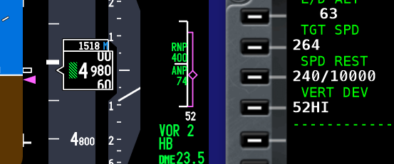
Montage showing Vertical Deviation Scale & vertical development display on PFD, ND and CDU respectively
The VDS is a solid white-coloured vertical line with three smaller horizontal lines at the upper, lower and middle section, on which a travelling magenta-coloured diamond is superimposed. The middle horizontal line represents the aircraft’s position and the travelling diamond represents the vertical bearing (V/B).
The VDS display represents the aircraft’s vertical deviation from the FMC’s determined descent path (vertical bearing) within +- 400 feet. It operates in a similar way to the Glideslope Deviation Scale on the Instrument Landing System (ILS).
When the aircraft is within +- 400 feet of the vertical bearing, the diamond will begin to move, indicating that the aircraft is above, below or on the V/B target. When the aircraft is on target (middle horizontal line), the FMA will annunciate IDLE thrust mode followed by THR HLD as the aircraft pitches downwards to maintain the vertical bearing to the next waypoint.
Important Point:
For the VDS to be displayed, a descent and approach profile must be selected from the CDU. The VDS will be displayed no matter what type of approach is used (RNAV, VNAV, VOR, etc).
In some literature this tool is referred to as the Vertical Track Indicator (VTI).
Vertical Development (VERT DEV)
The Vertical Development (VERT DEV) display can be found in the Descent page in the CDU. The displayed number is the numerical equivalent of the Vertical Deviation Scale. The Vertical Development will display HI or LO prefixed by a number which is the feet the aircraft is above or below the desired glide path; the number will be displayed after the discrepancy has exceeded 50 feet. This information is also duplicated by the display of white-coloured numerals beneath the Vertical Development Scale in the ND.
The Vertical Deviation Scale and Vertical Development display will remain visible on the PFD, ND and CDU throughout the approach. Both tools are important aids to cross reference during a Non Precision Approach (NPA).
Additional Information
Vertical Bearing Indicator (as earlier article concerning the VBI.
Final Call
The traditional method of a step down approach, which was the mainstay used in the 1970s has evolved with the use of computer systems and GPS. In the 1980s RNAV (area navigation) approaches with point to point trajectories began to be used, and in the 1990s these approach procedures were further enhanced with the use of Required Navigational Performance (RNP) in which an aircraft is able to fly the RNAV approach trajectory and meet specified Actual Navigation Performance (ANP) and RNP criteria. From the 1990s onward with the advent of GPS, the method that non precision approaches are flown has allowed full implementation of the RNP concept with a high degree of accuracy.
Although the nature of non precision approaches has evolved to that of a 'precision-like' approach with a constant descent angle, there are operators that widely use these techniques, despite their flaws, weaknesses and drawbacks. Even if modern navigational concepts are used in conjunction with traditional methods, aids such as the Vertical Bearing Indicator, Altitude Range Arc and the Vertical Development display should not be overlooked. Appropriate cross checking of the data supplied by these aids provides an added safety envelope and avoids having to remember, calculate and rely on ‘back of the envelope’ calculations.
The flight crew landing in Canberra, Australia did not use all the available aids at their disposal. If they had, the loss of vertical situational awareness may not have occurred.
UPDATED: 02 September 2025
Abbreviations
ALT - Altitude
ANP - Actual Navigation Performance
ARA - Altitude Range Arc
CDU – Control Display Unit (used by the flight crew to interface the with the FMC)
FAF - Final Approach Fix
FMS – Flight Management System
FMA – Flight Mode Annunciation
FMC – Flight Management Computer (connects to two CDU units)
ILS – Instrument Landing System
KIAS - Knots Indicated Air Speed
MAP - Missed Approach Point
MCP – Mode Control Panel
ND – Navigation Display
NPA – Non Precision Approach
RoD – Rate of Descent
RNP - Required Navigation Performance
RNAV - Area Navigation
TDZE - Touchdown Zone Elevation (runway threshold)
ToD – Top of Descent
V/B – Vertical Bearing
VBI – Vertical Bearing Indicator
V/S – Vertical Speed
VDS – Vertical Deviation Scale and pointer (also called Vertical Track Indicator)
VERT DEV – Vertical Development
WPT - Waypoint


