Reference Nav Data - CDU Functionality Explained

In past posts, I’ve documented some of the functionality of the Flight Management Computer (FMC) as displayed by the Central Control Unit (CDU).  Following on with this theme, let’s look at four navigation data functions the FMC is capable of: Reference Nav Data, Nav Options, Nav Status and Nav Frequency Changes.

Before continuing, the FMC/CDU is controlled by the avionics suite you are using; whether it is ProSim737, Sim Avionics or whatever.  Each avionics suite provides differing functionality; therefore, if something does not operate as indicated, it maybe a limiting factor of the avionics suite in use.

Note:  This post follows standard terminology.  lsk3R means line select key 3 right.

------------------------------

A:  REFERENCE NAV DATA

Occasionally, you will need to cross check information and the frequency of a specific navaid.  

The Reference Nav Data display is part of the Nav Data page and can be assessed by the INDEX page:

INIT REF / INDEX / NAV DATA (lsk1R)

The screen will show three available options: Enter WPT Ident, Navaid Ident and Airport Ident.

Example:  Type HB into the navaid Ident.  Two pages will be displayed showing all the HB Idents from the navigation database.  Selection of the appropriate navaid (HB) will present a further page displaying the following information:  Navaid WPT, Airport and Ident code, Latitude, Longitude, Frequency, Elevation and magnetic variance.

NOTE:  If you cannot identify the ident by name use the Longitude and Latitude coordinates.

------------------------------

B:  NAV OPTIONS & NAV STATUS

Following on from the Reference Nav Data page are:  Nav Options and Nav Status.

Nav Options and Nav Status can be assessed two ways:

1:  INIT REF/ INDEX / NAVDATA (lsk1R) / NAV OPTIONS (lsl6R)  

2:  PROG (progress) / NAV STATUS (lsk6R)  (use when in flight)

Two consecutive pages are available: Nav Options and Nav Status.  By default, Nav Status (page 2/2) is displayed.  Use the PREV and NEXT PAGE keys to cycle between the two pages.

Nav Status - page 1/2

This page provides you with a list of the closest navaids including frequencies.  It also indicates the currently set identifier and frequency for NAV 1 and NAV 2 (as set on the NAV 1/2 radio).

Nav Options - page 2/2

This page can be used to inhibit a particular waypoint or station.  By inhibiting a navaid, it will not be able to be used by the CDU to calculate a navigation solution.  By default all navaid types are activated.  At crew discretion, two VOR and two DME stations can be inhibited.  When you inhibit a navaid it will be removed from page 1/2 and not be visible in the Nav Status page list.  The inhibited navaid will be reset when you reset the CDU.  

------------------------------

C: FREQUENCY CHANGE - ALTERING THE CDU

In usual practice, crew will alter the navigation, communication, ADF and transponder frequency on the actual panel located in the central pedestal.  However, often you may need to cross check frequencies, dial in a third frequency for positional awareness, or use a frequency from an avionics module not present in the pedestal or that is malfunctioning.

The alter Nav Data screen can be assessed by:

MENU / MAINT (lsk6R) / COM/NAV (lsk3L)

This will display a page showing all idents and frequencies currently being used.

COM 1, COM 2, NAV 1, NAV 2, ADF 1, ADF 2 AND EXPR

To alter a frequency, type into the scratch pad the frequency of the navaid and upload to the appropriate line.  To upload, select and press the key to the left or right of the nominated radio.  Changing a frequency in the CDU will also cause a corresponding change in the frequency of the selected radio (in the center pedestal).

Flow Route

When you work through the above four functions of the CDU, you will note that the INDEX function is always available.  This allows you to easily develop a flow route as you move between the various pages.  Once you know how the flow route operates, you will discover that the CDU is very much like a book with several hundred pages of information that is easily accessible via a few select menu keys.

As with all my posts, if you discover a discrepancy please contact me so it can be rectified.

BELOW:  Montage of images from the CDU showing various pages displayed within the Reference Nav Data.  CDU is manufactured by Flight Deck Solutions (FDS).  Click image to see larger.

Montage of images from the CDU showing various pages displayed within the Reference Nav Data.  CDU is manufactured by Flight Deck Solutions (FDS)

B737 Auto Brakes - Converting & Using a Genuine Auto Brake

oem 737-500 auto brake rotary and squib

Enthusiasts don’t normally give a second thought to the rotary type auto brake mechanism on the Main Instrument Panel (MIP); it works and that’s all that matters.  However, several reproduction rotarys do not entirely replicate the correct operation of the auto brake in the Boeing 737 aircraft.

In the real aircraft, a pilot has the ability to select between auto brake OFF, 1, 2, 3, and MAX.  The first three brake indications and off are achieved by turning the knob in a clockwise or anticlockwise direction, however, the knob stops at MAX.  To engage MAX, the pilot must pull the knob out from a retainer and then move it a further click to the right. 

The reason for this is quite simple; engaging auto brake MAX results in severe deceleration which can be stressful and uncomfortable for passengers, as well as creating undue wear and tear on the braking mechanism of the aircraft.  The function of pulling the knob is not replicated in reproduction auto brake switches.

Aviation Scrap Yard to Me

To my knowledge, the auto brakes operate and use the identical rotary mechanism throughout the Boeing aircraft series, the exception being the size and style of the actual knob mounted on the rotary.  The early model auto brake assemblies have a slightly larger knob, while those used in the 737-500 have a smaller knob that is identical to that used in the Next Generation aircraft (with the exception of the parallel black strips which is distinctly Next Generation) 

rear of own autobrake squib

Larger and Robust

If you have inspected any genuine aviation part, you will have noted that the size of the item is usually quite large in contrast to reproduction simulator part.  This is because a real part must be manufactured to take into account the nuances of pressure, fatigue, vibration, water and dust proofing, and be made as sturdy as possible to ensure operational longevity.  Genuine parts regularly are designed to military specifications and can withstand considerable abuse.   

Canon Plugs

The wiring used with an OEM part can appear complex with several wiring harnesses and a multitude of connections.  In a real aircraft, these wires connect to circuit breakers and a magnitude of interconnecting electrical components and power sources. All Boeing 737 aircraft use Canon plugs. Canon plugs make removing a panel straightforward for a technician and also provide a fail safe mechanism to ensure that specific wires are connected to their correct mate. Each Canon plug is different and can contain up to 32 differently arranged pin-outs. It is almost impossible to miss-mate two Canon plugs.  

With so many variables, it can be frustrating slow process determining which is the correct pin-out to use. 

Autobrake Mechanism -  Simpler than Most Conversions

The auto brake assembly is a lot simpler to convert than a more sophisticated avionics panel. 

If you already have an auto brake rotary and installed to your MIP, all you are doing is replacing the reproduction plastic rotary with a real OEM rotary.  The wires then connect to your interface card.  The only tricky part is determining which connection outlet on the real rotary to connect the wires to.  Determining this is either by trial and error or finding a schematic diagram for the rotary.  I was fortunate that I had access to the later…

using a dremel bit to carefully enlarge the hole in the panel so that the rotary shaft will fit correctly

Conversion and Retrofit

Remove from the MIP the reproduction auto brake rotary and front light plate.  Check to determine if the shaft of the genuine rotary will fit through the panel and MIP wall; the circumference of the hole may need to be widened.   If this is necessary, it’s important that you do not damage any IBL back lighting that maybe used in the light plate.  IBL is usually sandwiched between the back and front of the panel.

I used a dremel tool to gently and very carefully remove part of the light plate to allow the rotary to fit through the hole in the plate.  Do NOT use a drill as this may fracture the light plate.  

Fitting the Rotary Nut - Enlarging the Plate Recess

The rotary is securely connected to the MIP via a hexagonal-shaped nut.  Depending on your MIP manufacture, you may need to enlarge the hole on the rear of the plate to enable this hex nut to be recessed in the plate.  If you are using a MIP made by Flight Deck Solutions you will not need to do this as FDS have designed their MIP to fit genuine parts.  Use the dremel to gently enlarge the recess on the rear of the plate.  Be VERY careful not to damage the light plate; use the dremel tool very lightly.  

owm 737-500 auto brake squib showing multiple connectors and pin out codes

Wiring

The genuine rotary appears to look like a squid (the sea animal) with an assortment of wires emanating from screw connectors.

Remove all the wires and screws and thoroughly clean the unit with a suitable cleaner.  Do not discard the wires and connectors as you can probably reuse the high grade aviation wire; remember recycling is good and helps the environment.  You will note that each connector is marked by a printed number.  

The numbered keys for the autobrake squib keys and function are outlined below:

  • 31 - common or earth

  • 32 - RTO

  • 33 - OFF

  • 34 - autobrake 1             1

  • 35 - autobrake 2

  • 36 - autobrake 3

  • 37 - autobrake MAX

Replace the screws in the appropriate connectors you will need to use.  Then add a section of wire (use the old wire first) to the connectors.  If you cannot reuse the sturdy clips, then use automobile electrical tabs.

If you have not done so already, before you cut the wires from the (to be replaced) “plastic” rotary, mark with tape and pen which wires connect to what function – RTO, OFF, 1, 2, 3 & MAX.  This will make it an easier task when reconnecting or soldering the wires.

Aligning Rotary on MIP

Aligning the autobrake rotary is important if you want the selector knob to align correctly with the engravings on the MIP.  If you look carefully at a reproduction rotary you will notice a circular lug that often is mated with a hole in the receiving metal - this stops the rotary from spinning on its own axis.  OEM parts do not have such a lug.  Rather, they have a circular washer that has a lug attached to it.  This washer slides over the shaft of the rotary along a defined groove.  The lug on the washer then meets with an appropriately positioned hole in the MIP to stop the rotary from swivelling.

Interface Card

If you are replacing a reproduction unit with an OEM unit, then an interface card is not necessary - connect the wires from the new rotary to those cut from the removed from the plastic reproduction rotary either by solder or using a terminal block.

However, if this is a new installation a Phidget 0/16/16 interface card will be required to assign the appropriate locations of the knob to their respective functions.

Is There a Difference?

Can I notice and feel the difference between the older reproduction rotary and the genuine rotary?  In a nutshell - a resounding yes. 

The genuine rotary is firmer to turn, engages with a distinctive audible click, and feels more robust.  The knob also feels different to the reproduction knob; probably because the reproduction knob is made totally from acrylic and a genuine knob, although made from similar material, has a stainless shroud around the inside of the knob.  This causes the knob to feel more secure on the rotary.

Annunciators

The autobrake has two annunciators - the Anti Skid INOP and the Autobrake Disarm korrys.   The simulator uses OEM annunciators and although these korrys have been wired separately, their connection with the autobrake is done through the avionics software in use.

Below is a short video showing the use of the auto brake assembly.  Ignore the speed reference knobs and fuel reset switch that need to be replaced with OEM knobs.


Auto Brake Usage

The auto brake is designed as a deceleration aid to slow an aircraft on landing or in rejected take off.  The rotary switch has four settings: RTO (rejected take off), 1, 2, 3 and MAX (maximum).  The brake can be disengaged by turning it to OFF, by activating the toe brakes, or by advancing the throttles; which deactivation method used depends upon the circumstances and pilot discretion.  

RTO and MAX provide similar braking power (3000 PSI).  1, 2, 3 and MAX provide an indication to the severity of braking that will be applied when the aircraft lands.   Often, but not always the airline will have a policy to what level of braking can or cannot be used; this is to either minimize aircraft wear and tear or to facilitate passenger comfort.  

In general, setting 1 and 2 are the norm with 3 being used for wet runways or very short runways.  MAX is very rarely used and when activated the braking potential is similar to that of a rejected take off; passenger comfort is jeopardized and it’s common for passenger items sitting on the cabin floor to move forward during a MAX braking operation.  This 'safety feature' is the reason why Boeing airframes have been designed so that the pilot must pull the auto brake knob before selecting MAX.

If a runway is very long and environmental conditions good, then a pilot may decide to not use auto brakes favoring manual braking.

The pressure in PSI applied to the auto brake and the applicable deceleration is a follows:

  • Auto brake setting 1 - 1250 PSI / 4 ft per second.

  • Auto brake setting 2 - 1500 PSI / 5 ft per second.

  • Auto brake setting 3 - 2000 PSI / 7.2 ft per second.

  • Auto brake setting MAX and RTO - 3000 PSI / 14 ft per second (above 80 knots) and 12 ft per second (below 80 knots).

To activate the auto brake it must be armed by selecting the appropriate setting using the auto brake selector knob (1, 2, 3 or MAX).  Furthermore, for the auto brake to engage the throttle thrust levers MUST BE in the idle position at touchdown.  If the auto brake has not been selected before landing, it can still be engaged providing the aircraft is travelling no slower than 60 knots.

The auto brakes can be disengaged by either pilot by applying manual braking or selection the auto brake selector knob to OFF.  Either action will cause the auto brake disarm annunciator to illuminate for 2 seconds before extinguishing.

Important Facet

It’s important to grasp that the 737 NG does not use the maximum braking power for a particular setting (maximum pressure), but rather the maximum programmed deceleration rate (predetermined deceleration rate).  You can only obtain maximum braking pressure using either RTO or when depressing the brake pedals.  Therefore, each setting (other than RTO) will produce a predetermined deceleration rate, independent of aircraft weight, runway length, type, slope and environmental conditions.

Auto Brake Disarm Annunciator

The auto brake disarm annunciator is coloured amber and illuminates when the following conditions are met:

  • Self test when RTO is selected on the ground.

  • A malfunction of the system (annunciator stays illuminated - takeoff prohibited)

  • Disarming the system by manual braking during an RTO or landing

  • Disarming the system by moving the speed brake lever from the UP position to the DOWN detente position.

  • If a landing is made with the selector knob set to RTO (not cycled through off).  If this occurs the auto brakes are not armed and will not engage.  The annunciator will remain illuminated

The annunciator will extinguish in the following conditions;

  • Auto brake logic is satisfied and auto brakes are in armed mode.

  • If the thrust levers are advanced during an RTO or landing ( 3 second delay is allowed after the aircraft has landed).

Personal Preference and Anti-skid

My preference for using auto brakes is, that when conditions are not ideal (shorter and wet runways, crosswinds) - I devote my attention to the use of rudder (for directional control) without concern for braking.

Anti-skid automatically activates during all auto braking operations and is designed to give maximum efficiency to the brakes, preventing brakes from stopping the rotation of the wheel, thereby insuring maximum braking efficiency.

To read more on this subject navigate to: Rejected Takeoff (RTO) - Review and Procedures.

BELOW:  Photo montage of auto brake assembly.  Final conversion lower right picture - ready to install to MIP.

Photo montage of oem 737-500 auto brake.  Final conversion lower right picture - ready to install to MIP

B737 Blanking Plates - Cover That Unsightly Gap

OEM blanking plates complete with DZUS fasteners recently removed from a scrapped 737 - the dirt and dust is still on them!  Note three differing sizes - 1" 2" and 4"

No matter what style of simulator you are using or have constructed, you will most likely have a center pedestal installed.  The pedestal will be either a two-bay or three-bay type and be a genuine aviation part incorporating DZUS fastener rails, or a reproduction unit manufactured from wood, metal or plastic.

The two-bay pedestals, once allotted the standard Boeing avionics suite, usually have no  space remaining for additional avionics; however, the three-bay pedestals have substantially more 'real estate' and often gaps are remaining that are not filled with avionics.  Most enthusiasts either leave this space open which looks very unsightly, or manufacture their own plate to cover the gap.

OEM Blanking Plates

Why not use the real part….  

Boeing produces several blanking plates in varying sizes to be used to cover any 'gaps' not used in the center pedestal, forward and aft overhead panel, or Main Instrument Panel (MIP).  These plates are machine-grade light weight steel (or aluminum), are painted Boeing grey, and incorporate the required number of DZUS fasteners for attachment to DZUS rails.  The plates come in a variety of sizes with 1 inch, 2 inch, and 4 inch being the norm.

These plates are inexpensive and usually retail between $5.00 - $20.00 USD, and not only fulfill the task of covering an unsightly gap, but are easy to install, come pre-cut, are painted the right colour, and usually have DZUS fasteners attached to them. 

If not using real DZUS rails and your pedestal in made from wood or plastic, then it’s relatively easy to remove the fasteners and replace them with reproduction screw-type DZUS available from GLB Products.

Most aircraft wrecking yards carry these plates, as airlines regularly purchase them.  Failing this E-Bay often has blanking plates for sale. 

737 Classic Flight Deck - Scrap to Home Flight Deck

oem 737 cl scraped flightdeck ©

I thought I'd post an image of how a flight deck appears after removal from the aircraft. This is a flight deck belonging to a Boeing 737 classic series which is the model previous to the 737 Next Generation.  Anything of value is slowly being removed for either scrap metal, repair and reuse, or for possible inclusion in a home flight deck. 

One aspect of flight deck building I enjoy is finding and using recycled parts.  Who said recycling cannot be enjoyable  :)

I've made this image full size, so if you want to see it in more detail click the image (image use courtesy of Tim ©).

B737 Training - Videos by Angle of Attack (AoA) - Basic Review

 “In the later part of the evening and occasionally into the wee hours of the morning, a hearty group of individuals - most of them seemingly rational, grown men and women with professional daytime jobs - sit perched in front of computer monitors with sweaty palms tightly clenching flight yokes.  Distant cries of "Honey, come to bed" have long since fallen on deaf ears as, with razor-sharp concentration, these virtual airmen skilfully guide their chosen aircraft down glide paths to airports across the world.  The late night silence is shattered by screeches of virtual rubber on the runway immediately followed by the deafening whine of reverse engine thrusters and finally a sign of relief from the flight deck - also known, in many instances as a desk! “

Why do we enjoy flight simulator?  

Is it the technical challenge learning integrated computer generated management systems, or the enjoyment of landing a virtual jetliner on a runway in limited visibility and a crosswind.  Perhaps it’s the perception of travelling to far flung locations that you probably would never visit, or maybe it’s the enjoyment received from constructing something from nothing (a flight deck).  

Which Aircraft Today - Basic Airmanship

There are many people very happy messing about with whatever they are flying.  Some will be using home computers and a joystick, others small generic style flight decks – all will have, to some degree, a level of airmanship. 

Whatever level, every individual will require at some point instruction in “how to fly” and "how to use the various avionics and instrumentation" - more so in B737 than a Cessna 172.

Flight Training –Remove Automation

A high-end simulator is a substantial investment both in time and funds.  Therefore, to obtain the best “Bang for Buck” as the Americans say, it’s more satisfying to accomplish a flight the correct way rather than the wrong way.  The B737 has numerous interfacing flight management systems and it’s important to understand what these systems do and how they interact with each other in certain phases of flight.

Flying the B737 in auto pilot mode is not difficult; the Flight Management System (FMS) does most of calculations and work for you and if you use autoland - well what else is there to do but watch.  But flying this way can be counterintuitive as you don’t really have full control of the aircraft; to fully appreciate the aircraft for what it is, you must deactivate the auto pilot and other automation and fly “hands on”.

Once the automation is deactivated, task levels multiply as several layers of information present themselves; information that must be assimilated quickly to enable correct decisions to made.  There's little room for second guessing and you must have a good working knowledge of how the various flight controls and systems interact with each other.  Add to this, inclement "virtual" weather, limited visibility, navigational challenges, landing approaches, charts, STARS, NDBS, VORS and a crosswind, and you'll find you have a lot to do in a relatively short space of time; if you want to land your virtual airliner in one piece.  And, this is not mentioning your pet dog nuzzling your leg wanting immediate attention or your girlfriend querying why the dirty dinner dishes haven't be washed!!

books contain a lot of information, however, they rely on the reader already having a good understanding of the 737 systems

Technical Publications

A lot of information is readily obtainable from technical publications, on-line sources, and from the content of forums.  There are several excellent texts available that go into depth regarding the technical aspects of the B737 and cover off on a lot of the topics a real and virtual pilot may need to know (I will be looking at a few of them in future posts).  But, for the most part these texts are technical in nature and are do not include the "how to" of flight training.

One very good source of information is the B737 Flight Crew Operations Manual (FCOM).

Tutorials - PMDG

Two “how to” tutorials written by Tom Metzinger and Fred Clausen are in circulation.  These tutorials deal with the Precision Manuals Development Group (PMDG) B737 NG. These tutorials provide an excellent basis to learning how to fly the B737 and what you need to do during certain phases of flight.  Two further tutorials are available for the 737 NGX, however, they are not freely obtainable unless you have purchased the PMDG B737 NG or NGX software package.

That Nagging Feeling……Correct or incorrect ?

Despite the books, tutorials and manuals, there's always that nagging feeling that something has not been covered, is incorrect, or has been misunderstood.  We all have heard the saying “there are several ways to skin a cat”; flying is no different.  A B737 line instructor informed me that there is "a huge amount of technique allowed when flying the B737""There are certainly wrong ways to do things; but, there is often no single right way to do something".  Often the method selected is not at the discretion of the pilot flying, but more the decision of airline management, company policies and ATC.

Visit any FS forum and you will quickly realize that many virtual flyers do things differently.  So where does this leave the individual who wants to learn the correct way?

Short of enrolling into a real flight class, which is time consuming, very expensive and a little “over the top” for a hobby, the next option is to investigate various on-line training schools.  To my knowledge, there aren’t many formal style training classes available that provide training in the B737.  

Angle of Attack Flight Training (AoA)

Angle of Attack has developed a reasonably priced and thorough training program that incorporates ground, line and flight training for a number of differing aircraft types.   Only recently has AoA completed their B737 ground and flight training video presentations, in what amounts to many hours of valuable training.

Much of the training material is presented in video format which can either be downloaded to your computer, mobile device or viewed on-line. The content of the videos is very high resolution, well structured, professionally narrated, easy to follow, and most importantly – interesting and informative.  

HD Video, Tutorials, Flows & Checklists for all B737 Systems

AoA have followed the real-world aviation industry standard by providing a lot of system training using "flows".  A flow is a animated diagram showing step by step the correct method of doing something.  In many instances a .pdf document can be downloaded to provide a "memory jogger" for you to replicate the flow when in the simulator.

Many of the training videos build upon knowledge already gained from texts such as the Flight Crew Operations Manual (FCOM), and the use of video as opposed to only reading, provides a differing method of education which helps you to develop a greater understanding.

Video flight tutorials which take you through from pushback to shutdown and demonstrate the correct procedure for conducting a flight.

AoA only provides training for the B737 NGX, however, much of the material is backwards compatible with the B737 NG series airframes.  The video training utilises the 737 NGX model produced by Precision Manuals Development Group (PMDG) and does not use a real aircraft.

Despite these two shortcomings (NGX & not a real aircraft), the training offered is exceptional, one of a kind, and in my opinion reasonably priced.  

Magnetic Declination - FS9, FSX, P3d and MSFS-2020

VOR (VHF omnidirectional range), Fort Lauderdale-Hollywood International Airport, Florida (Sharon Hahn Darlin, VOR (VHF omnidirectional range), Fort Lauderdale-Hollywood International Airport, Florida June 2021 01, CC BY 2.0)

Flight simulator whether it be FS9 or FSX, is quite long in the tooth as far as software programs go.  These programs was released several years ago and during this time span there have been many improvements in computer technology and in real world flying procedures.  When released, FS9 and FSX contained the latest navigational data, including the correct declination, VOR, and ILS radio frequencies; however, these are now out of date with real world counterparts.  

Magnetic Declination

Magnetic declination has a very important influence on air navigation, beginning with the use of the standard compass and sectional flight chart.  Similarly, radio navigation aids on the ground, such as VORs use magnetic variation to ensure reliable and accurate in-plane navigation.  The direction of the runway also relies heavily on magnetic variation and runway directions often require updating to ensure that ILS systems operate as designed. 

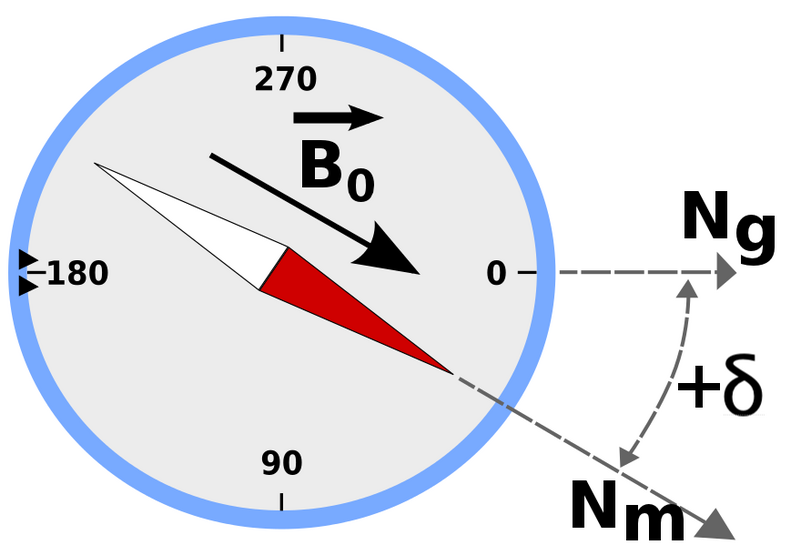
Simply explained, magnetic declination is the difference between true north and magnetic north and the value changes each year.  Flight Simulator is referring to a value that was accurate when the software was developed but has changed considerably in the ten years plus since the program was released. 

I realized a problem existed when I noticed that the direction of the runway did not align correctly with the latest navigational database installed into ProSim737 (Navigraph).   The CDU continually issued advisory warnings informing me that the runway direction and database were not identical.  Although it's possible to ignore the warning advisory, it becomes tiresome to continually reset the CDU  whilst in the more demanding phase of approach and landing.

Updating Magnetic Variation

Screen grab of program interface

Updating this data is easy thanks to Herve Sors.   Herve has developed a free stand alone program that easily and quickly updates the magnetic variation in either FS9 or FSX whilst also providing the opportunity to rectify out of date and changed runway directions.  The information can be updated globally or by country region, and if necessary you can revert back to the old data.

Without going into unnecessary detail, the program decompresses, corrects, and compiles the necessary information within the .BGL files, located in the scenery folder of flight simulator; it's in this folder that the various navaids are recorded.

Do I need To Update ?

The ability of simulator to accurately simulate navigation is only as good as the navigational database installed.  Think of the database as a street directory or telephone book - do you want to search the directory for out-of-date information?  The update is a very simple process and takes but a few minutes and it's strongly recommended.

By updating virtual pilots will benefit at the very least from:

  • All VOR and NDB data will be up-to-date, allowing chart usage to easier with current charts.

  • Correct calibration of magnetic declination of navaids that provide an azimuth information (VOR/VORDME/NDB) that will be greatly improved matching the "as real as it gets" experience while navigating (tracking navaid radials will be as it is indicated on charts).

  • ILS data (for those that are corrected, Europe only at this time) will be correct.

To download the required software (FSX World NavAids 4.32 & MagVar Data) and investigate Herve's various other programs, navigate directly to his website at AeroSors NavAids.

The software also updates the database for Prepar3D and MSFS-2020.

Replacement Sidewalls for FDS MIP

I have mentioned in an earlier post concerning the Main Instrument Panel (MIP) from Flight Deck Solutions, that the unit was a little wobbly due to the thin metal used on the side-walls.  Whilst this is not a major problem, and certainly not an issue when the MIP is locked into a shell, it does pose a minor issue when used without a shell.   Therefore, I decided to fabricate some replacement side stands for the MIP from 3mm aluminium sheet.

AutoCad was used to copy the dimensions of the original FDS sidewalls, and a laser cutter cut the aluminium sheeting to the exact measurement.  Using a standard pipe bender, I bent the sides out at 45 degrees to allow slightly larger spacing for the rudder pedals.  I also increased the surface area of the metal which is used to attach the MIP to the platform, this ensures a more stable and secure attachment point for the MIP.  To replicate the MIP side-walls exactly, I TIG welded the narrow section that folds behind the stand.

Currently the aluminium is unpainted.  At some stage in the near future I'll either have the two units powder-coated in Boeing grey to match the colour of the MIP, or more than likely I'll prime and paint them myself.

The MIP is now very stable and does not wobble at all.

2012 - 2013: Seasons Greetings, Thank You & 2013 Plans

First, "Merry Christmas and Seasons Greetings"

Flaps2Approach has been live since the 737 project commenced in September 2010.  On average, each week the site receives over 10,500 individual hits and 32,000 page views from nearly every developed country on the planet.  I hope the site has provided YOU with information, ideas, interesting reading, and enthusiasm to either begin or continue your own 737 project.

I enjoy documenting the project; I find it helps clear my thoughts!  I hope I have not made too many spelling or grammatical mistakes in the posts.

Thank You

A project of this magnitude is not a one person job; many people have provided advice, assistance and most importantly their personal time in helping me achieve what you see today.  I'd like to thank each person for their help; a number of you (you know who you are...) have been exceptionally patient with me as I learn new skills to add to my quiver.

2012 - Almost Gone!

The new year will be upon us shortly and although much of the construction of the flight simulator has occurred during the past year, 2013 will see some major enhancements as the simulator evolves further toward a fully workable simulator. 

Milestones accomplished during this year have been the conversion of the 737-300 throttle quadrant, two converted OEM 737 ACP units, a replacement of the former platform with a more sturdy, functional platform, and installation of dual rudder pedals and OEM control columns.

What's Planned - 2013

On the near horizon we will see the implementation of full automation of the Boeing 737 throttle quadrant and complete functionality of the speed brake system which will replicate exactly the operational status of the real aircraft.  It's also hoped that OEM parts will become available to develop the forward and aft overhead.  This is in addition to replacing some of the reproduction gauges on the MIP with converted OEM components, such as the brake hydraulic and flaps indicator gauges.

Later in the year, the method in which the overhead is to be mounted will be decided (roll frame or shell) and the external visuals, which to date have not been adequately addressed, will be looked at in detail. 

No doubt, as 2013 progresses there will be a host of other small improvements and most importantly, the opportunity to spend some time behind the yoke actually flying - which I have sourly missed for the past 15 months or so....

OEM Boeing 737 Control Columns - A Closer Look

OEM Captain-side 737-500 series control column.  Previously used by Croatian Airlines

The two control columns have been refurbished and installed into the simulator.  The control columns previously were used in a 737-500 airframe operated by Croatian Airlines. 

I was fortunate to have been able to secure these columns, and although there is some wear on the yokes, the buttons, electric trim switches, chart holders, and trip indicators are operational and in good condition.  Furthermore, a working stick shaker is attached to the captain-side control column.

In this article, I use the words control columns and yoke interchangeably.

Mechanical Set Up

To allow the two columns to be fitted to the 5 inch high platform, the lower cogs have been removed and replaced with bearings.  The bearings support a high strength stainless shaft that connects to a rotating disc beneath each of the columns; movement is synchronised between control columns.

Physical movement of the control column is registered by high-end string potentiometers and any movement converted to an electrical signal that can be read by the interface card.  The interface card used is a Leo Bodnar 836X joystick controller.

The interface card, electrical wiring and potentiometers are installed on a piece of plastic board mounted to a dust proof box and attached to the underside of the platform.  Access to the box is via the front of the platform.

Control Force Push and Pull Pressure

The 737‑800 uses a mechanically‑linked, hydraulically‑powered elevator control system with artificial feel provided by the Elevator Feel and Centering Unit. Typical control column forces in normal operation are light to moderate because the hydraulics carry the aerodynamic load, but force increases with airspeed due to the feel system’s airspeed‑sensed pressure. There is a fail-safe cable mechanism that provides redundancy should the hydraulics fail. 

The 737 is rather unique in that, although hydraulics control movement of the control column, the pressures needed to move the columns (by hand) are quite stiff.  Therefore, hand flying a 737 can be quite tiring; you must use a little muscle to move and maintain the position of the controls.

Based on the system design:

  • At low speed: Forces are light; the feel unit provides minimal resistance.

  • At climb/cruise speeds: Forces increase noticeably; the feel unit stiffens the column to prevent excessive pitch inputs.

  • At very high speed (near Vmo/Mmo): Column forces become significantly heavier to protect the aircraft from overstress.

  • In hydraulic failures: With one hydraulic system lost, forces increase. With both systems lost (extremely rare), the aircraft reverts to manual reversion, and forces become very heavy, requiring two‑handed operation.

The specifications for the real aircraft state that the control column has a 37 pounds push/pull value +- 4 pounds, while the roll pressures are 12 pounds +- 3 pounds.  These pressures can differ from aircraft to aircraft, but fall within the published specifications. To replicate the push, pull and roll forces as accurately as possible, four heavy duty springs have been fitted to the column mechanism. 

Heavy duty pre-tensioned springs provide accurate static control loading

The control column pressure can be adjusted by either replacing the springs with higher or lesser tension springs, or by disengaging the outer springs. 

A pressure test determined that push/pull pressure is 20 pounds and roll pressure 15 pounds.  The push/pull pressure is on the low side, however, will be left as is for the time being.  Springs have been used rather than hydraulic rams due to the simplicity of a spring and ease of replacement.

The main springs are made by Century and are part number C-267

Spring specifications - main springs used for yoke and column by century (c-267)

Although the use of springs is rudimentary, it's acts as an interim measure until control force feedback is installed.  When this is done, the force required to move the control column will alter based on aircraft's speed, flap setting, landing gear position and other environmental variables. This will be a software option.

The video at the bottom of this article demonstrates the linkage mechanism and springs in motion.

Configuration - Movement and Buttons

Configuration of the control columns is straightforward. Although there are two control columns, each column is linked to the other.  Therefore, only one interface card is required.  The buttons on the yoke, and the electric trim switch are connected to the outputs on the interface card.

Initial registration of the movement of the yoke and buttons is established in the Windows joystick calibration software.  Further calibration is either done directly in the flight simulation program, FSUIPC, or in ProSim737.  Although it is possible to assign buttons directly via the flight simulator set-up menu, the preferred method is to use FSUIPC or ProSim737.

Backlighting (Trip Indicators)

The actual yoke doesn't have backlighting; any illumination of the yoke is achieved by focusing the map light which is attached to the overhead panel.  However, the numbers on the trip indicators do have backlighting (to illuminate the numbers). 

Trip indicators are an airline specific option and do not come as standard issue.  Pilots use the trip indicator to 'scribe' the flight number of the flight, or to document the Vref speed.  Some crews never use the indicators.  I use the trip indicator as a ready memory pad to document the landing Vref speed (Vref+5).  The backlighting for trip the indicators is powered by 5 Volts.

oem chart holder and cheat sheet

Chart Holder

The chart holder is used to secure the approach plate (paper chart) in an area that it can easily be read during flight operations.  The chart holders have a folding mechanism beneath the plate that allows the holder to be either pushed flush to the yoke, or positioned at a user-selected angle. 

Another function of the chart holder is to provide a ready memory jogger for specific flight modes (checklist).  The adhesive transfer on which this information is printed is specific to each aircraft type and /or airline.  illumination of the chart plate, like the yoke, is achieved using the map light.

OEM Verses Reproduction

Several companies manufacture reproduction control columns: Precision Flight Controls (PFC), CH Products, Revolution-Sim and Ace Engineering to name a few.  Over the years I have used products from ACE, CH Products and PFC.  Without transgressing into a 'tit for tat' argument, you get what you pay for.  

A CH yoke retailing at $100.00 cannot be compared with an ACE yoke retailing around $1300.00, however, both products have been manufactured to cater towards differing segments of the market.  This said, the difference between ACE and PFC is marginal.  I cannot comment on Revolution-Sim having not used their products. 

So what is the different between a high-end reproduction yoke and a OEM yoke and column?

The main difference is the feel and finesse of the genuine item.  Boeing has spent a lot of money (more than PFC, ACE or Revolution-Sim combined) in the development and engineering of the control column, and this is very difficult to replicate in a reproduction.

The OEM yoke and column is engineered to provide faithful service for many years.  It's also built to suffer use and abuse from real-world pilots, and I am certain anything a virtual pilot can throw at it, will not cause any damage.  The buttons and electric trim switches are solid, feel good to manipulate and are very reliable.

Yoke Performance

The yoke moves left and right across its range of motion with a smooth and silky feel without staggering, binding or rough patches.  Likewise, the columns move forward and aft very smoothly.

The electric trim switches are far more responsive than the reproduction switches I have used.  A slight application of pressure to the switch engages the electric trim.  The electric trim switches response is a akin to a hair trigger on a firearm - it only needs a light touch to engage. 

The control column is very responsive, and if calibration has been done correctly, very accurate.  If the yoke is turned 15 degrees to the left, the measurement on the aileron tape is exactly 15 degrees.

Synchronisation

I was concerned that synchronisation between the two control columns would not be perfect, however, my concern was short-lived.  The use of high-end bearings at the end of the control linkages removes any chance of slop (loose movement) between the two control columns. 

Yoke Switches

  • OEM 737 yokes have several switches and buttons.

  • Momentary press push button - auto pilot deselect.

  • Momentary rocker switch - electric trim up/down. This switch is interesting as it incorporates redundancy.

  • Momentary rocker - push to open channel (push to talk PTT).

  • Rocker switch - Intercom.

  • Trip Indicator - used as memory aid for flight number.

oem 737 flight controls in simulator

Appearance of Yoke - Used Look

If you carefully study the pictures of the yokes, you will observe that the yokes are not pristine condition, but show solid use (and probably abuse when it was striped from the aircraft).

The baked-plastic covering of the yoke shows scratches and some of the metal has been rubbed clean of paint.  Some enthusiasts dislike this look and prefer a brand new 'out of the showroom' appearance.  If this is you, then I suggest an OEM yoke may not be for you, unless you wish to completely overhaul the yoke and pay the large amount of money required to re-bake the plastic coating.

I like the 'used' look and feel it adds to the simulator.  I have been in many cockpits, and very rarely do you find a flight deck in brand new condition, other than in the first few months of service.  More often than not, gauges, yokes and panels are scratched, dented and stained from many hours of sustained use from individuals that are more interested in flying, and going home after the flight, than maintaining the desk!

Below is a short video showing the under floor mechanism, springs and linkage rods.  If you listen carefully you will hear the springs creaking.  This is not an issue when the simulator is running as any noise is cancelled out by the noise of the engines and flight deck ambient noise (electrics, 400 hertz, noise, wind etc).


Glossary

Control Wheel - Yoke.

FSUIPC - Flight Simulator Universal Inter-Process Communication (interface software that provides a bridge between flight simulator and outside programs).

OEM - Original Equipment Manufacturer (aka real aircraft part).

  • Updated 20 June 2020.

Digital Chronograph Running ProSim737 Software

The Main Instrument Panel (MIP), unless a special order is made, usually will not include a chronograph.  Depending upon the MIP manufacturer, the MIP may have a cut out for the chronograph, a facsimile of a chronograph or just a bezel. 

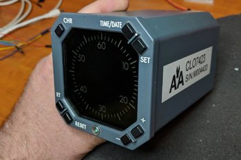
LEFT:   OEM chronograph used by America Airlines.  Although nothing beats an OEM item, in this case conversion is difficult; therefore; a reproduction chronograph was more cost effective.  Image courtesy of Micks737.

The Next Generation aircraft mostly use digital chronographs. The classic series airframes usually use (unless retrofitted) mechanical chronographs.

After Market Chronograph

There are several after-market chronographs that can be purchased.  SISMO Solicones produce a mechanical type that replicates the real world counterpart quite well, despite the awful orange-coloured backlighting.  Flight Illusion produces a quality instrument as does Flight Deck Solutions (FDS).  FDS replicate the digital chronograph. 

Chronographs are manufactured by several companies and not every chronograph looks identical, although their functionality is.  There are a few different styles available to an airline.  The main difference is in the number and shape of the buttons; round or rectangular.

No matter which type you decide, be prepared to shell out 250 plus Euro per chronograph; for an item rarely used it's quite a financial outlay.

Converting OEM Chronograph

Converting an OEM B737 mechanical chronometer is a valid option and the process of conversion is relatively straightforward.   However, finding a mechanical chronograph in operational order is difficult, as airlines frequently keep chronographs in service for as long as possible.  Converting a digital chronograph is also an option, however, the initial price of the item and then conversion make this an expensive exercise.  Add to this the fact that converting the chronograph, due to its internal digital electronics is very difficult (even if you use ARINC 429 protocol).

Another option is to use the virtual chronometer (Sim Avionics and ProSim737) and fabricate a reproduction bezel that overlays a small LCD screen.

ProSim737 Virtual Chronograph

Screen capture of ProSim737 chronograph.  ProSim737 have a Chronograph that can be used for the Captain and First Officer side of the MIP

ProSim737 as part of their avionics suite have available a virtual chronometer.

The display used by ProSim737 is very crisp, the size is accurate (1:1 ratio), and the software allows complete functionality of the chronograph. 

To use the virtual version a small computer screen is needed on which is displayed the virtual chronograph.

Chronograph

A friend of mine indicated that he wanted to make a chronograph for the simulator and use the virtual ProSim737 display.  He also wanted to incorporate the four setting buttons and have them fully functional. 

The components needed to complete the project are:

  • A small TFT LCD screen (purchased from e-bay);

  • A standard Pokey interface card;

  • Several LEDS; and,

  • Four small tactile switches and electrical wire. 

I currently use an Main Instrument Panel (MIP) fabricated by Flight deck Solutions (FDS).  Therefore, the chronograph bezel used in this project was that supplied by FDS.

The screen used was 5.0" TFT LCD Module with a Dual AV / VGA Board 800x480 with a 40 Pin LED Backlight. 

The screen was small enough that it just covered the circular hole of the cut out in the FDS MIP.  The TFT LCD screen uses a standard VGA connector cable, 12 Volt power supply and a USB cable to connect the POKEY card to the computer.  

The holes in the box provide ventilation for the Pokeys card.  The only portion of the box that is visible from the front of the MIP is the bezel and four buttons

Two-part Fabrication

FDS supply with their MIP a bezel with four solid plastic but non-functional buttons.  The bezel does not support direct backlighting, nor does it have enough space for tactile switches or wiring. 

Therefore, the FDS bezel must be modified to accommodate the wiring for the switches and LED illuminated backlighting. The easiest way to approach this modification is to use a Dremel rotary tool with a 9902 Tungsten Carbide Cutter.

Place the bezel on a hard surface using a towel to avoid scratching and damaging the bezel.  Then, with 'surgical' accuracy and steady hands carve out several channels (groves) at the rear of the bezel.  The channels enable placement of the miniature tactile switches, small LEDS and wiring. 

Space is at a premium, and to gain addition real estate, the LEDS were shaved to remove excess material.  This enabled the LEDS to fit into the excavated groove on the bezel.  Be very careful when using the carbide cutter to not punch out onto the other side of the bezel. 

The four solid plastic front buttons on the bezel are carefully removed and small tactile switches attached (glued) to the rear of each of the buttons.   26/28 AWG wire is used to connect the tactile switches (using common ground leads) to a PoKeys interface card. 

The box is not seen as it's attached to the rear of the MIP.  My friend's humour - several warning signs suggesting that I not tamper with his creation :)

Box Fabrication

A small box needs to be fabricated to house the Pokey card.  The size of the box is controlled by the size of interface card used and the length and width of the LCD screen. 

A box is not required, however, it's a good idea as it illuminates the need to seal the LCD screen to illuminate dust ingress between the screen and overlying glass in the bezel. 

The material used to fabricate the box is plastic signage card (corflute); real estate agencies often use this type of sign.  The main advantage of this material is that it’s not difficult to find, is light in weight, and it's easy to cut, bend, and glue together with a glue gun.    

After the Pokey card is installed to the inside of the box, and the LCD screen attached to the front edge, the bezel needs to be secured to the front of the LCD screen.  The best method to attach the screen and bezel is to use either glue or tape. 

A hole will need to be made in the rear of the box to enable the fitment of the USB and VGA connectors.    Small holes punched into the side of the container ensure the LCD screen and PoKeys card do not overheat.  If you're concerned about heat buildup, a small computer style fan can easily be added to the box, but this does add complexity and is not necessary.  To conform to standard colours, the box is painted in Boeing grey.

LED Backlighting

Careful examination of the backlighting will show that the light coverage is not quite 100%.  There are two reasons as for this.

(i)    There is limited space behind the bezel to accommodate the wiring and the LEDS; and,

(ii)   The material that FDS has used to construct the bezel is opaque.  The only way to alleviate this is to replace the stock bezel with another made from a transparent material.

Important Point:

  • If you want to try and replicate the digital OEM chronograph as closely as possible, that the OEM version does not use backlighting.  Illumination of the front of the chronograph is by the MIP lighting.

Potential Problem

Depending on the MIP being used, there maybe space constraints that do not allow a 5 inch screen to be easily positioned.   If you're forced to use a smaller screen, the outcome will be that you may see the screen edges within the bezel.  For the most part this is not an issue, if you ensure the desktop display is set to black.  Remember, you are looking at the chronograph from a set distance (from the pilot seat) and not close up.

ProSim737 Virtual Chronograph (position and set-up)

This task is straightforward and follows the same method used to install and position the PFD, ND and EICAS displays.  

Open ProSim737’s avionics suite and select the virtual chronograph from the static gauges:  resize and position the display to ensure the chronograph conforms to the size of the bezel.  To configure the buttons on the bezel, so that ProSim737 recognizes them with the correct function, open the ProSim737 configuration screen and configure the appropriate buttons from the switches menu (config/switches).

The four functions the buttons are responsible for are:

(i)    Chronograph start;

(ii)    Set time and date;

(iii)   Expired Time (ET) and Reset; and,

(iv)   +- selection

NOTE:  The above functions differ slightly between the panel and the virtual chronograph in use.

Chronograph Operation and Additional Configuration

Captain-side CLOCK start button.  Connection between the clock button and the CHR button is made in the assignments page in ProSim737 (FDS MIP)

The chronograph can be initiated (started) by either depressing the CHR button on the top left of the clock, or by depressing the CLOCK button located on the glarewing of the MIP. 

Configuration

Connecting the CLOCK button to the chronograph start (CHR) function is straightforward.

Connect the two wires from the Captain-side clock button to the appropriate interface card and configure in the switches tab of ProSim737 (config/switches/CAPT CHR).

The same should be done with the First Officer side CLOCK button and chronograph, however, ensure you select the FO CHR function in switches to be done for the First Officer side chronometer if fitted.

If configured correctly, one press of the CLOCK button will start the chronograph, a second press will stop the chronograph, and a third press will reset the chronometer to zero.

After Market Chronograph

For those wanting to use an after market chronograph, SimWorld in Poland and Flight deck Solutions (FDS) in Canada produce high quality chronographs that can be dropped into the MIP with minimal required fabrication.

Video

A short video (filmed at night) showing the new chronograph running the virtual ProSim737 software.  Note that the chronograph displays is slightly smaller in the video to what it should be.  Adjusting the size of the display is done within the ProSim737 software.


Update

on 2020-06-18 03:27 by FLAPS 2 APPROACH

Another flight deck builder has also constructed a chronograph using similar methods.  His chronograph uses a different design that does not use a box. 

Update

on 2020-05-23 01:00 by FLAPS 2 APPROACH

In August 2019 this chronometer will be replaced.  The replacement will use a similar design, however, will not be encapsulated in a box that fits behind the MIP.  The new design will incorporate a å larger 5" TFT LCD screen that will enable more screen real estate for the chronograph.  The screen will be mounted directly to the rear of the MIP and the interface card will be adhered to the rear of the screen. 

The reason for changing the design is two-fold:

  1. The box is quite large, and the weight (although light weight) is heavy enough to cause the bezel to pull away from the MIP; and,

  2. Accessing the interface card is difficult (as it's inside the box).

An article explaining the process will form a new article.  The new chronograph very closely follows the design used by FlightDeck737.BE

Modular Floor Structure / Base Platform Installed

Portion of floor structure showing modules bolted together with control columns and rudder pedals installed to structure

Although it has taken longer than anticipated, the second platform to replace the platform made from wood and MDF fibreboard has been completed. 

The new design is constructed from aluminium flat tubing, is modular, and incorporates the mechanical hardware needed for operation of the OEM 737 control columns. 

The structure comprises two main sections - the modular floor structure, and floor (called the base platform).

Centre platform with ABS plastic floor structure attached. Note the shiny appearance.  This was later removed by painting

The modular design of the platform, which in addition to allowing easy disassembly and transport (if required), also allows the platform to be increased in size by adding further modules.  For instance, if I decide to add an instructor station in the future it will be straightforward to manufacture another module and bolt it to the existing framework.  The hollow underneath section also provides an ideal area for the hidden storage of wires, power boards, and other pieces of necessary equipment such as external speakers and sound systems.

Two aft modules with flooring fitted, rudder pedals in background on forward command module

Access to the underside of the base platform (floor) is via several well-positioned hatches.  Removal of a hatch (4 screws) enables access to whatever is beneath the floor.The platform comprises ten modules which are bolted together at strategic locations to ensure the structure is rigid, strong and sturdy.  Each module has several cross stays that have been welded in place ensuring adequate support for the weight which will be placed on the platform (Weber seats, MIP, throttle unit and people).

The first three modules, which I call the command module, have been constructed as one unit and house the rudder pedals, control columns and incorporate the duel linkage rods and other mechanical hardware for control column and rudder pedal operation.  Although this unit can be separated into the three modules (by removing the attachment bolts, springs and linkage rods),

Half circle flange and seal around control column and drill holes through floor that match corresponding hole in aluminium framework.  Bolts have been used to secure Weber seats.  In the second picture of this series, you can see the claw feet secured by four bolts through the flooring to the support beneath

it’s best to leave them attached, as removing the steering mechanism and associated equipment is a complicated and timely operation.

Behind the forward command module are three secondary modules to allow attachment of the two Weber seats and throttle quadrant.  The MIP is attached to two smaller and narrower modules bolted at the front of the command module; whilst at each side two longer and narrow modules provide side support. 

Platform Height and Dimensions

The height of the platform measures 16 cm (6.3 inches) and the total weight, including the two rudder pedals, internal mechanisms and control columns is approximately 160 kilograms (353 pounds).  At this weight, it certainly will not be sliding anywhere.

The platform is not a full size platform as space availability at the current time is limited, however, if and when I wish to move into a full size platform, it will be easy to incorporate and bolt additional correctly sized modules to the existing structure.

Installing Weber Seats

The Weber seats need additional support as seat movement can generate stress at the connection point of the claw feet and floor.  To ensure the seats fitted securely and any stress of seat movement was absorbed by the platform and not just the floor structure, the claw feet bolt directly through the floor to the aluminium tubing structure.  Therefore, the platform absorbs the stress when the seats are moved rather than the flooring.

Platform Floor - ABS Plastic

In the real aircraft the floor is made from pressed aluminum which is studded (rivets) in strategic locations to ensure it is solidly fixed.  Various hatches (hinged and otherwise) are present in certain areas to facilitate access to areas beneath the sheeting.

Builders use many different products for the floor, ranging from MDF fibreboard, ply and aluminium to tin or plastic.  I was intending to use thin aluminium sheeting as a platform floor, however, when I discovered the price I decided to use something less conventional.

A supply of heavy duty ABS plastic was readily available; the advantage of this material being it doesn’t require painting as it’s already coloured Boeing grey, is easy to cut and work with, is of a thickness and weight that can withstand the intended weight and finally, doesn’t flex.  Rather than use one large sheet of board for the platform cover, which would be unmanageable, the sheet has been cut to fit each corresponding module.  The sheets are attached to the aluminium tubing of the module by normal stainless screws. If the material doesn’t hold up to my expectations, I’ll replace it with aluminium or quality ply board. 

Although the ABS plastic is coloured grey, I found it to be too shinny in appearance.  Preparing the ABS plastic for painting was straightforward and entailed thoroughly cleaning the plastic with detergent to remove any residue oil.  Then the plastic was lightly scoured using a low grade sandpaper.  This creates a suitable texture for the paint to adhere.  The ABS sheeting was then painted with one coast of epoxy plastic primer and two coats of matt Boeing grey. 

The ABS plastic and paint has held up to use very well.  Even after scuffing, and moving the throttle quadrant onto and off the floor several times the paint and plastic has not been damaged.

One downside of using ABS plastic can be electrostatic discharge.  If you wear socks on the platform and rub your feet on the ABS plastic a charge can build-up.  I have yet to discover a way to stop this from occurring (other than wearing shoes).

Perhaps I will upgrade the ABS floor at some stage to a full aluminium floor, but at the moment I am more than content with the use of ABS plastic.

Tyre inner tube cut and stretched to fit beneath control column flange.  The overlapping area of rubber tube sits over the bulbous part of the control column lever with the floor

Installing the Control Columns, Rudder Pedals and Column Flange

The floor has been cut and the hole shaped to accommodate the control columns and rudder pedals.  The various linkage rods and internal mechanisms have either been either bolted or welded directly to the lower platform superstructure.

The half circle flange (or whatever Boeing call it) that surrounds each control column on the floor was constructed from light metal.  To replicate the rubber-like seal that is often observed above at the lower end of each control column, a piece of recycled inner tyre tube was used.  The rubber was cut and easily stretched to fit beneath the half circle flange. 

The Main Instrument Panel (MIP) is secured to the platform by several bolts strategically placed on the MIP.

Computer and Sound System Installation

The two computers that are needed to operate the simulator will be positioned at the front of the platform where access is relatively easy to both power supplies and the MIP.  The sound system, which comprises three speakers and a sub-woofer speaker, will be placed directly beneath the floor structure. In the first picture, you can just see the sub-woofer speaker towards the end of the platform.

New Platform Verses Former Platform

The structure of the first platform was from wood, and access to the underside of the platform from the side was next to impossible.  The floor was made from two large sheets MDF fibreboard and although sealed and painted, still appeared to release gases (MDF fibreboard releases gas and requires sealing for indoor use).  The structure and flooring was very solid, but access to anything beneath the floor (maintenance) was difficult.

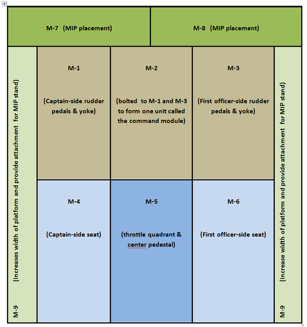
BELOW:  Diagram layout of modular design.


Update

on 2016-07-19 23:25 by FLAPS 2 APPROACH

Several individuals have requested the dimensions of the platform, which is smaller than a standard platform.  The benefit on being modular is that you can easily add sections to the platform to increase its size.

Platform Size

  • Overall Length:  183 cm

  • Overall Width:  183 cm

  • Height:  16 cm

  • Module M7: Overall Length: 183 cm (each piece left and right is 83.5 cm in length)

  • Module M7: Width 15.5 cm

  • Module M9: Length 167 cm

  • Module M9: Width 15.5 cm

  • Module M1, M2 & M3: Length 85 cm

  • Module M1, M2 & M3: Width 53 cm

  • Module M4, M5 & M6:  Length 81 cm

  • Module M4, M5 & M6:  Width 53 cm

If you are attempting to accommodate a OEM 737 column linking mechanism, the height of the platform will need to be considerably higher (in the order of 10-12 inches height) to house the lower cog mechanism of the columns.

Sheepskin Seat Cover added to Weber Captain-side Seat

sheepskin seat cover added to oem weber seat

Sometime ago I acquired a pair of Weber pilot seats which came with the correct Boeing diamond-pattern, grey honeycomb seat covers.  However, one of the seat covers was slightly damaged.  The lower cover was also a tad on the small side and kept popping off the rear section of the lower cushion when you sat on it.  Not a major problem, but it was slowly becoming irritating having to repeatedly attach the cover back on the cushion.

The small size was probably caused by the previous owner washing the seat cover;  Boeing covers are renowned to shrink substantially when washed in hot water!  To rectify these minor problems, I decided to have the captain’s side upgraded to a sheepskin seat cover.

A friend of mine has access to high quality Boeing-style sheepskins and being a wizard at sewing, agreed to retrofit the cover for me.

It should be noted that sheepskin covers are not attached to the seat like you would do on an automobile.  Rather, the sheepskin is sewn directly onto the existing fabric of the original seat cover.  Colour varies somewhat depending upon the manufacturer awarded the Boeing contract, but in general they are grey to tan in colour.

I think you will agree, that the final outcome looks, and certainly feels, much better than the original damaged and too small seat cover.

B737-300 Throttle Full Automation Upgrade

oem 737-300 throttle formally used by South West Airlines. Note grey coloured throttle levers and raw aluminum handles. The boxes that contain the TOGA buttons can just be seen

The throttle quadrant installed in the simulator is from a 737-300.  When I initially  converted the throttle for flight simulator use, I choose to not have full automation included; automation being at the time fraught with issues in relation to correct and accurate operation.  

Technology rarely remains stationary and after one year of operation I’ve been reliably informed that automation can now be implemented without the problems previously experienced.  Therefore, I’ve crated the throttle quadrant and it’s now on its way to the US via DHL courier for conversion to full automation.  A process I am told that will take a few weeks.

Automation will include, at the minimum, the following:

  • 4 speed trim wheels dependent upon aircraft status (as in the real aircraft)

  • Accurate trim tab movement

  • 9 point speed brake (speed brake operation as in the real aircraft)

  • Full automation of throttle thrust handles as per MCP speed window and/or CDU

  • Hand brake release by depressing brake pedals (as in the real aircraft)

I don’t mind admitting that that my building abilities don't include complete knowledge on how to convert a 737 throttle correctly - especially in relation to automation; therefore, this task has been outsourced.

The method in which automation will be achieved is slightly different from the usual way throttles are converted, and includes some magic programming of chip sets and machining of parts to allow compatibly with ProSim737.  Taking into account Christmas and New Year, I'm hoping that the machining, installation, configuration and testing will be completed by January (2013) and the throttle will be re-installed into the simulator by February.

In a future post, I will explain the process of conversion, and how automation has been achieved with minimal use of add-on software.

Idle Time

Although the throttle quadrant and pedestal will be absent from the simulator for a short time, work will not be idle.  The conversion of the twin real B737 yokes and columns has been completed and I'm finalising installation of the second platform which incorporates linked 737 rudder pedals.  I am hoping this will be completed by mid-November.  I have discussed the new platform in a previous post.