Trim Wheel Nut Tool - New Design

The redesigned Trim Wheel Nut Tool. Fabricated from a solid piece of aluminium

A potential problem when using an OEM Boeing throttle unit, is removing the nut that secures the trim wheels to the side of the throttle.  The nut has been designed in such a way that loosening it can only be done with a specialised tool.  Attempting to use a screwdriver or pliers may burr the nut, or slip causing damage to the trim wheel.

In an earlier post I examined how a simple tool had been designed to easily remove the nut from the spline shaft that holds the trim wheels in place.   Although this tool was functional there was room for improvement in its design and manufacture.

New Design and Improved Engineering

The tool, has been redesigned and incorporates an aluminium cylinder that has been produced from a solid block of aluminium using a milling machine.  The inside of the cylinder has been milled and a set screw securely inserted.  The set screw mates with the screw that holds the spline shaft in place.

The outer flange, adjacent to the set screw has then been machined so that two ridges, approximately 1mm in height are either side of the set screw.  The set screw mates with the female located on the end of the spline shaft while the ridge provides extra purchase by mating with the indents in the nut. 

In addition, a circular hole 8mm in diameter has been drilled through the upper portion of the cylinder enabling a similar sized piece of metal, or the shaft of a screwdriver to be inserted.  This allows additional purchase and leverage should the nuts be difficult to loosen.   Finally, the aluminium on the outside of cylinder has been slightly scoured to facilitate better grip.

New design has easier mating which enables greater purchasing power for removing tight spline nuts

Round and Round

The trim wheels are continually rotating back and forth as the aircraft is trimmed.  This rotation causes the nut, that secures the trim wheels to the spline shaft to, over time, become tighter and therefore more difficult to loosen.  This firmness is often exacerbated if working on a throttle unit removed from a real aircraft, that has not had the spline nuts removed for several years; corrosion and caked grease can easily cement the nuts in place.

This tool, although not an OEM part, is more than adequate to loosen the most determined trim wheel nut.

Knobs Aren't Knobs - Striving for the Perfect Knob

The real item – a Boeing Type 1 General Purpose Knob (GPK) and issue packet.  There can be nothing more superior to an OEM part, but be prepared to shell out a lot of clams

In Australia during the early 1980’s there was a slogan ‘Oils Ain't Oils’ which was used by the Castrol Oil Company.   The meaning was simple – their oil was better than oil sold by their competitors.  Similarly, the term ‘Knobs aren’t Knobs’, can be coined when we discuss the manufacture of reproduction knobs; there are the very good, the bad, and the downright ugly.

Boeing Knobs

As a primer, there are several knob styles used on the Main Instrument Panel, forward and aft overhead, various avionics panels, and the side walls in the 737-800 Next Generation. 

If you search the Internet you will discover that there are several manufacturers of reproduction parts that claim their knobs and switches are exactly identical to the OEM knobs used on Boeing aircraft – don’t believe them, as more often than not they are only close facsimiles.

In this article, I will primarily refer to the General Purpose Knobs (GPK) which reside for the most part on the Main Instrument Panel (MIP).  Boeing call these knobs Boeing Type 1 knobs.

oem 737 -800 next generation knob. note different location of set screw. knob used on overhead

Why Original Equipment Manufacturer (OEM) Knobs Are Expensive

Knobs are expensive, but there are reasons, be they not be very good ones.  

The average Boeing style knob is made from painted clear acrylic resin with a metal insert. On a production basis, the materials involved in their manufacture are minimal, so why do OEM knobs cost so much…   Read on.

There are two manufacturers that have long-term contracts to manufacture and supply Boeing and Airbus with various knobs, and both these companies have a policy to keep the prices set at an artificially high level.

Not all flight decks are identical, and the requirements of some airlines and cockpits are such that they require knobs that are unique to that aircraft model; therefore, the product run for knobs for this airframe will be relatively low, meaning that to make a profit the company must charge an inordinate amount of money to cover the initial design and production costs.

A high-end plastic moulding machine is used to produce a knob, and while there is nothing fancy about this type of technology and the process is automated, each knob still requires additional work after production.  This work is usually done by hand.

Cross section of a Boeing Type 1 General Purpose Knob

Once a knob has been produced, it must be hand striped and finished individually to produce a knob that is translucent and meets very strict quality assurance standards.  Hand striping is a complex, time consuming task. 

Additionally, each knob must undergo a relatively complex paint spraying procedure which includes several coats of primer and paint, and a final clear protective coating.  Spray too much paint and the translucent area (called the pointer) inside the twin parallel lines will not transmit light correctly.  Spray too little paint and the knob can suffer from light bleed.  There is a fine line during production when it is easy to ruin an otherwise good knob with a coat of thickly applied paint. 

Finally, any part made for and used by the aviation industry must undergo rigorous quality assurance, and be tested to be certified by the countries Aviation Authority.  Certifying a commercial part is not straightforward and the process of certification takes considerable time and expense.  This expense is passed onto the customer.

Often disregarded during the manufacture of reproduction knobs is the inner metal sleeve.  The sleeve protects the material from being worn out from continual use

Replicating Knobs - OEM Verses Reproduction

It’s not an easy process to replicate a knob to a level that is indiscernible from the real item.  Aside from the design and manufacture of the knob, there are several other aspects that need to be considered: functionality, painting, backlighting, robustness and appearance to name but a few. 

Backlighting and Translucency

To enable the knob to be back lit calls for the knob to be made from a translucent material.  Unfortunately many reproduction knobs fall short in this area as they are made from an opaque material.

The knob must also be painted in the correct colour, and have several coats of paint applied in addition to a final protective layer.  The protective layer safeguards against the paint flaking or peeling from the knob during normal use.  In the photograph below, you can see where extended use has begun to wear away part of the knob's paint work revealing the base material.

Detail of the grip and metal set screw.  The set screw is important as it enables the knob to be secured against the shaft of the rotary.  This knob previously was used in a Boeing 737-500

Set Screws and Metal Inserts

Often lacking in reproduction knobs is a solid metal set screw (grub screw).

The task of the set screw to secure the knob against the shaft of the rotary so that when you  turn/twist the knob it does not rotate freely around the shaft.  Plastic set screws can be easily worn away causing the knob to freely rotate on the shaft of the rotary encoder. 

The position of the set screws on the knob also deserves attention.  Correctly positioned set screws will minimize the chance of rotational stress on the shaft when the knob is turned.

Of equal concern is the hole on the underside of the knob where the rotary shaft is inserted.  The hole should be sheathed in metal.  This will increase the knob’s service life.  If the hole does not have a metal sheath, it will eventually suffer from wear (disambiguation) caused by the knob being continually being turned on its axis.   Finally, the knob must function (turn/twist) exactly as it does in the real aircraft.

Reproduction knobs may fail in several areas:

(i)    The knob has various flaws ranging from injection holes in the molded plastic to being the incorrect size or made from an inferior plastic material;

(ii)    The knob does not use metal set screws, and the set screws are not located in the correct position on the knob;

(iii)    The knob has a poorly applied decal that does not replicate the double black line on Next Generation General Purpose Knobs.  The adhesive may not be aligned correctly and may peel away from the knob;

(iv)    The knob is made from a material that does not have the ability to transfer light (translucent pointer);

(v)    The knob does not appear identical in shape to the OEM part (straight edge rather than curved);

(vi)    The paint is poorly applied to the knob and peels off.  OEM knobs have several thin coats of paint followed by hard clear coating of lacquer to ensure a long service life;

(vii)    The colour (hue) of the knob does not match the same hue of the OEM product; and,

(viii)    The circular hole in the rear of the knob, that connects with the shaft of the rotary encoder does not have inner metal sleeve.  

The time it takes to manufacture a knob is time consuming, and to produce a quality product, there must be a high level of quality assurance throughout the manufacturing process.

Older Classic-style Knobs

It's common knowledge that many parts from the classic series airframe (300 through 500) are very similar, if not identical to the parts used in the Next Generation airframe.  Unfortunately, while some knobs are identical most are not.

The knobs may function identically and be similarly designed and shaped, but their appearance differs.  Knobs used in the Next Generation sport a twin black-coloured line that abuts a translucent central line called the pointer, classic series knobs have only a central white line.

Rotary Encoders

Although not part of the knob, the rotary encoder that the knob is attached deserves mention.

An often quoted quib is that an OEM knob will feel much firmer than a reproduction - this is not quite true.  Whilst it is true that an OEM knob does has a certain tactile feel, more often than knot the firmness is caused by the rotary that the knob is attached to.

Low-end rotary encoders that are designed for the toy market are flimsy, have a plastic shaft, and are easy to turn.  In contrast, rotaries made for the commercial market are made from stainless steel and are firmer to turn.

Also, low end rotaries and knobs are made from plastic and with continual use the plastic will wear out prematurely resulting in the knob becoming loose.

Many reproduction knobs fit the bill, and for the most part look and feel as they should. It's easy to criticize the injected plastic being a little uneven along the edge, but this is unseen unless you are using a magnifying glass

Final Call

Whether you use reproduction or OEM knobs in your simulator is a personal choice; It doesn't play a huge part in the operation of a simulator.  After all, the knobs on a flight deck are exactly that – knobs.  No one will know you have used a reproduction knob (unless low end reproductions have been chosen).

However, the benefit of using a real aircraft part is that there is no second guessing or searching for a superior-produced knob.  Nor is there concern to whether the paint is the correct colour and shade, or the knob is the correct shape and design – it is a real aircraft part and it is what it is.  But, using OEM knobs does have a major set-back - the amount of money that must be outlaid.  

But, second-hand OEM NG style knobs are not easy to find and often there is little choice but to choose ‘the best of the second best’.

Increasing Paint Longivity - Avionics Panels

Testers Dullcote.  Although it can be applied by a brush, a better approach is to use an airbrush and spray a thin coat onto the panel. When applying Dullcote to a panel, it is best to spray an even thin coat

One of the most important items in a simulator is the panel; after all, you spend a lot of time looking at panels, and a scratch or major blemish can be rather off-putting.  

It is unfortunate, that the final grey-coloured coat of paint on many reproduction panels does not conform to the same level of quality assurance that Gables or Smiths provide on an OEM item. 

Some reproduction panels can easily be scratched and chipped, and after installing and removing a panel several times, or using it for a few months, the panel quickly can appear to look like a well-used item. 

Quality assurance is a term frequently used to discuss the quality of an item.  Many manufacturers of reproduction panels only apply one or two coats of paint which may or may not be applied over a primer.  The strength and longevity of the paint depends upon whether a primer has been used, the thickness of the paint, the quality of the paint and the number of applications.  Three thinly applied coats of grey-coloured paint over primer base is far better than one or two thick coats of paint without a primer. 

The final paint finish should not be shiny but be non-reflective.

So how can you improve the durability of paint after it has been applied? 

A product called Testers DullCote has been used in the modelling arena for many years.  Modelers apply a layer of Dullcoat to their models prior to applying other painting effects which may be damaging to the underlying base coat.   Dullcote dries to a clear matt texture that adds a layer of protection to the base coat of paint.  

The application of Dullcote can be either by rattle spray can, airbrush or by a standard modeling brush.  Whatever application method is chosen, always trial the product on a lesser item prior to applying to an expensive avionics panel.

If applied correctly, Dullcote will minimize the chance of a panel being scratched or blemished and provide a clear, durable, and flat texture that can easily be cleaned.  Additionally, if Dullcoat is applied to an OEM annunciator, the application will enhance the appearance of the annunciator making it appear clearer than possibly what it is.

Glossary

  • Gables and Smiths – Two manufacturers of OEM Boeing 737 avionics panels

  • Light Plate – The actual plate that contains the lighting array to backlight the cut-out sections on a panel

  • OEM – Original Equipment Manufacture aka real aircraft part

  • Panel – Used loosely to mean a avionics panel or module (for example Fire Suppression Panel or radio panel)

BRT / DIM Functionality - Lights Test Switch

Lights Test switch.  The three way switch located on the Main Instrument Panel (MIP) Captain-side is used to toggle the intensity of connected annunciators.  The panel label reads TEST, BRT and DIM.  The switch in the photograph is an OEM switch which has been retrofitted to a Flight Deck Solutions (FDS) MIP

The annunciators in the Boeing 737 are very bright when illuminated, and the reason for the high intensity is justified - the designers want to ensure that any system warnings or cautions are quickly noted by a flight crew.

However, when flying at night for extended periods of time the bright lights can be tiring on your eyes.  Also, during critical flight phases such as during a night-time approach, the bright lights can become distracting.  At this time, the flight deck is usually dimmed in an attempt to conserve night vision. 

For example, the three green landing annunciators (Christmas tree lights), speed brake and flaps extension annunciators are all illuminated during the final segment of the approach.  At full intensity these annunciators can, at the very least, be distracting.

To help minimize eye strain and to enable night vision to be maintained as much as possible, pilots can select from two light intensity levels to control the brightness output of the annunciators. 

Anatomy of the Lights Test Switch (also called a toggle)

The switch (a three-way toggle) which controls the light intensity (brightness level) is called the Lights Test switch.  The switch is located on the Main Instrument Panel (MIP).  The switch is not a momentary switch and whatever position the switch is left at it will stay at until toggled to another position.  The switch has three labelled positions: Lights Test, BRT and DIM. 

(i)           UP controls the lights test (labeled Lights Test);

(ii)          CENTER is the normal position which enables the annunciators to illuminate at full intensity (labeled BRT); and,

(iii)         DOWN lowers the brightness level of the annunciators (labeled DIM).

OEM annunciators have a built-in Push-To-Test function, and each annunciator will illuminate when pushed.  The brightness level, when pushed, is determined by the position the Lights Test switch (DIM or BRT). 

The Lights Test will always illuminate all the annunciators at their full intensity (maximum brightness). An earlier article explains the Lights Test switch in more detail.

Selecting the BRT / DIM switch to dim will lower the brightness of all the korrys on the MIP, fire suppression panel, and the forward and aft overhead, with the exception of those korrys that are deemed safety essential (special conditions).

Special Conditions

When the Light Test switch is set to DIM, all the annunciators will be illuminated at their minimum brightness.  The exception is the annunciators belonging to the Master Caution System (MCS), which are the master warning, fire bell and six packs, and the Autopilot Flight Director System (AFDS).  These annunciators will always illuminate at their full intensity because they are construed as primary caution and warning lights.

Variable Voltage

There is nothing magical about the design Boeing has used to allow DIM functionality; it is very simplistic.

In the real aircraft, the DIM functionality (and Light Test) is controlled by a semi-mechanical system comprising relays and zener-type diodes that vary the voltage.  The various Korrys require 28 volts to illuminate at full intensity while in DIM the voltage drops to 16.7 volts. This said, diodes are not necessary when replicating this system in the simulator environment.

Annunciators for the most part are powered by 28 volts; therefore, when the Lights Test switch is in the neutral position (center position labeled BRT) the bulbs are receiving 28 volts and will illuminate at full intensity.  Moving the switch to the DIM position reduces the voltage from 28 volts to 16.5 volts with a correspondingly lower output. 

Two Controlling Systems - your choice

The DIM and Lights Test functionality can be achieved in the simulator by using one of two systems - software or mechanical.

Software Controlled

The avionics suites developed by Prosim-AR, Project Magenta and Sim Avionics have the ability to conduct a full Lights Test in addition to allowing DIM functionality.  However, depending upon the hardware used, the individual Push-To-Test function of each annunciator may not be functional.  The DIM functionality is controlled directly by the avionics suite software; it is not a mechanical system as used in the real aircraft.

In ProSim737 the DIM function can be assigned to any switch from the configuration/switches and indicators menu.  In Sim Avionics the function is assigned and controlled by FSUIPC offsets within the IT interface software.

Mechanically Controlled

I have chosen to replicate the Lights Test and DIM functionality in a similar way to how it is done in the real aircraft. 

There are no benefits or advantages to either system – they are just different methods to achieve the same result.

Power Supplies, Relays and Amperage

Two Meanwell power supplies are used to provide the voltage required to illuminate the annunciators during the lights test.  A 28 volt 14.6 amp power supply enables the annunciators to be illuminated at their brightest intensity, while the less bright DIM functionality is powered by a 15 volt 10 amp power supply (or whatever voltage power supply you wish to use).

To obtain the voltage that best corresponds to the brightness of the annunciators, the V-ADJ (voltage adjustment) screw located on each power supply will need to be adjusted accordingly. Meanwell power supplies enable you to increase or decrease the output voltage to fine tune the power supplies output to your specific circumstances. In this instance, the 15 volt power supply is adjusted upwards so that the voltage output is 16.7 amps.

The two power supplies are linked in series (daisy chained) to other power supplies in the power supply rack. This facilitates the use of one power cable to the mains power. Additionally, a wire connects the two power supplies on the -DC side. This connection enables the ground (earth) to be part of the circuit no matter whether the lights test switch is set to BRT or DIM.

A heavy duty 20 amp 12 volt relay enables selection of either 28 volt or 16.5 volts (depended on position of lights test toggle).

The relay is powered by the 15 volt power supply, which when the lights are set to DIM is 16.7 volts. This overamps the relay by 4.7 amps. This is why it is recommended to use a quality high end 12 volt relay as they are usually rated to around 20 amps before they fail. If you prefer to remain within the established amperage range of the relay, either adjust the voltage on the power supply for the DIM to 12 volts or connect the relay to a 12 volt power supply. The difference in brightness between 12 volts and 16.7 volts is minimal, but is noticeable.

Second Option

If not wanting to use 2 power supplies, a single 28 volt power supply can be used if voltage reducers are connected to the power supply. In this option, two voltage reducers are attached to the 28 volt power supply each reducing the 28 volts to 16.7 volts and 12 volts respectively. Therefore, the korrys are powered by 28 volts when at full brightness (BRT - normal), 16.7 volts at DIM, and the 12 volt relay is powered by 12 volts.

The downside of this method is that it uses two voltage reducers which adds a small amount of complexity in contrast to a only using an additional power supply.

Amperage

Prior to purchasing a power supply (in this case 28 volts) it’s important to determine what amperage the power supply should be rated. If the amperage is too low, the annunciators will not illuminate as the amperage draw from the korrys will be greater than what the power supply can generate. If the amperage of the power supply is not high enough, options are to purchase a larger amperage power supply or link two power supplies of the same type and amperage in parallel. Linking two identical power supplies in parallel will effectively double the amperage.

Important Point:

  • Bear in mind that the Lights Test and BRT/DIM functionality affect all the korrys in the MIP, fire suppression panel, and in the forward and aft overheads. Depending upon the age of the korrys used (and their bulbs) the amperage draw maybe quite high. If this is the case, a higher rated (amperage) 28 volt power supply may be needed.

The DIM Board is surprisingly simple and comprises a single terminal block and a heavy duty 12 volt relay.  Wires are coloured and tagged to ensure that each wire is connected to the correct terminal

DIM Board

A small board has been constructed from ABS plastic on which is mounted a 20 amp 12 volt relay and a terminal block. The board, called DIM is mounted behind and beneath the MIP. This facilitates easy access to the required power supplies mounted within the Power Supply Rack (PSR)

An important function of the DIM board is that it helps to minimise the number of wires required to connect the DIM functionality to the various annunciators and to the Lights Test switch.   

Interfacing and Connections

Prior to proceeding further, a very brief explanation is required to how the various panels receive power. 

Rather than connect several panels directly to a power supply, I have connected the power supplies to two 28 volt busbars - one busbar is located in the center pedestal and other is attached to the rear of the MIP.  The busbars act a centralised point from which power is distributed to any connected panels.  This allows the wiring to be more manageable, neater, and easily traceable if troubleshooting is required.

Similarly, there is a lights test busbar located in the center pedestal that provides a central area to connect any panel that is lights test compliant.  Without this busbar, any panel that was lights test compliant would require a separate wire to be connected to the Lights Test switch in the MIP. 

The below mud schematic may make it easier to understand.  To view the schematic at full size click the image.

Mud schematic.  Note that grey box should say 12 Volts - not 28 Volts

A 28 volt busbar located in the center pedestal is used as a central point from which to connect various panels to (lower pale blue box).  

The busbar is connected to the terminal block located on the DIM board.  Wires from the terminal block then connect to a 16.5 and 28 volt power supply located in the PSR (orange boxes). 

The relay is also wired directly to the terminal block on the DIM board and a single wire connects the relay with the Lights Test switch located in the MIP (green box). 

From the Lights Test switch, a single wire connects with the lights test busbar located in the center pedestal (pale blue box in diagram).  The purple box represents any panel that is Lights Test compliant - a single wire connects between a panel and the lights test busbar.

Although this appears very convoluted, the principle is comparatively simplistic.

How it Works

When the Lights Test switch is toggled to the DIM position the relay is closed.  This inhibits 28 volts from entering the circuit, but allowing 16.5 volts to reach the 28 volt busbar (located in the center pedestal); any annunciators connected to this busbar will now only receive 16.5 volts and the annunciators will glow at their lowest brightness level.  Conversely, when the switch is toggled  to BRT or to Lights Test, the relay opens and the busbar once again receives 28 volts.

Which Annunciators are Connected to DIM Functionality

The annunciators that connect with the DIM board are those in the fire suppression panel, various panels in the center pedestal (that use 28 volt korrys), the forward and aft overhead, and in the MIP.  If further annunciators in other systems require dimming, then it is a matter of connecting the appropriate wires from the annunciator to the 28 volt busbar, and to the lights test busbar, both of which are located in the center pedestal.

  • The nomenclature for the 12 Volt relay is: 12 V DC coil non-latching relay part number 92S7D22D-12 (Schneider Electric).

BELOW:  A rather poorly produced video showing the two brightness levels.  The example shows the annunciators in the OEM Fire Suppression Panel (FSP).  The clicking sound in the background is the Lights Test switch being toggled from BRT to DIM and back again.  Note that the colour of the annunciator does not alter - only the brightness.  The colour change in the video, as the lights alter intensity, is caused by a colour temperature shift which is not visible to the naked eye but is recorded by the video.


Diagram showing passage of electricity through the circuit as the BRT/DIM toggle is selected (allow to video to play lead in)


A rather poorly produced video showing the two brightness levels.  The example shows the annunciators in the OEM Fire Suppression Panel (FSP).  The clicking sound in the background is the Lights Test switch being toggled from BRT to DIM and back again.  Note that the colour of the annunciator does not alter - only the intensity (brightness).  The colour change in the video, as the lights alter intensity, is caused by a colour temperature shift which is not visible to the naked eye but is recorded by the video.


Glossary

  • Annunciator - A light that illuminates under set conditions.  Often called a Korry.

  • Busbar - A bar that enables power to distributed to several items from a centralised point.

  • Mud Schematic - Australian colloquialism meaning a very simplistic diagram (often used in geological mapping / mud map).

  • Push-To-Test Function - All annunciators have the ability to be pushed inwards to test the circuit and to check if the globe/LED is operational.

  • OEM - Original Equipment Manufacturer aka real aircraft part.

  • Panel/Module - Used interchangeably and meaning an avionics panel that incorporates annunciators.

  • Toggled- A verb in English meaning to toggle, change or switch from one effect, feature, or state to another by using a toggle or switch.

  • UPDATED: 17 April 2025, 05 May 2025

Flight Testing The SimWorld MCP and EFIS

SimWorld MCP retrofitted into a Flight Deck Solutions (FDS) MIP.  Initial impressions exceed expectations, especially when comparing the appearance of the MCP to the OEM item

I have been using the Mode Control Panel (MCP) and Electronic Flight Instrument System (EFIS) produced by CP Flight.  These units have been the mainstay in the flight simulation community for several years and for the most part they are robust, reliable, and more or less look similar to the OEM units. 

Recently, other companies have begun to manufacture MCP and EFIS units to replicate the real aircraft part as closely as possible in both appearance and functionality. 

SimWorld, located in Poland is a relatively new company that is making great leaps forward designing and manufacturing reproduction 737 Next Generation panels and other components.  One of SimWorld's premier items is their 'plug and play' MCP and EFIS.

I am currently in possession of a SimWorld MCP and two EFIS units.  These units have been retrofitted into a Flight Deck Solutions (FDS) MIP and flight testing has begun.  In due course a detailed review will be published.  I also will be, at the same time, reviewing the CANBUS system that SimWorld use to connect their various panels to the computer and Flight Simulator.

To test and evaluate the unit will take some time as the protocols I use are very thorough.  In the next few months (depending upon time) I should have enough data to enable a detailed review to be written.  The review will address at the minimum the following:

  • Manufacturing technique (materials, painting, lazer cutting, etc);

  • Accuracy and scale to the OEM MCP/EFIS

  • Robustness and longevity;

  • Functionality to OEM unit;

  • Quality assurance;

  • SimWorld pre-sales and after-sales support;

  • Reliability and consistency in operation; and,

  • An overview of the CANBUS system.

Note that I have no affiliation with SimWorld, or any other manufacturer.  This review will be a balanced opinion based on my use and the use and opinion of other users of the MCP and EFIS unit.

Glossary

  • EFIS - Electronic Flight Instrument System.

  • MCP - Mode Control Panel.

  • MIP - Main Instrument Panel.

  • OEM - Original Equipment Manufacturer (aka real aircraft parts).

Update

UPDATE 07-03-2017 by FLAPS 2 APPROACH: There have been a few problems that needed to be sorted out on the MCP that was sent to me for evaluation.  After considerable testing by myself and SimWorld, it was determined the problem stemmed from a number of unreliable potentiometers.  These potentiometers were part of a bad batch delivered by the supplier.  Filip at SimWorld decided the best option was to manufacture a new MCP and this has only just been received via UPS.

Interestingly, the replacement MCP has a number of improvements over the old-style model which includes the use of Swiss-made commercial-grade potentiometers.

Over the next few weeks I will flight test the new-style MCP and document the results in a separate post.

Update

on 2017-04-07 07:02 by FLAPS 2 APPROACH

UPDATE 07-04-2017 by FLAPS 2 APPROACH: Finally, after considerable flight testing and editing a review which was very long, the final review of the SimWorld MCP and EFIS has been published.   I hope it answers the questions that many have been asking me in private messages and e-mails.

And to answer the question to whether I am impressed with the panels and will be keeping them in my simulator - Yes I will be - unless an OEM Collins panel appears at a reasonable price :)

Replacement Curtains - B737 OEM Throttle Dust Curtains

OEM dust covers for the Boeing throttle. there are slight colour variation depending upon manufactuer

Interesting items can arrive in the post.  Earlier today I opened a small parcel to find a collection of grey coloured pieces of material.  To anyone else they would appear exactly as they do – pieces of material stamped with numbers.

The throttle quadrant I use is original equipment manufacture (OEM) and once plied the skies above Europe.  As such it is a used item with the usual wear and tear you expect from a well-used aircraft part. 

One item that continually caught my attention was the dust curtains or skirts that sit behind the two thrust levers.  In my throttle, the curtains had been abused at some point and were torn and the edges looked rather ragged in appearance.  Although a replacement curtain could have been made by using vinyl or another similar material it would not be the same. 

The numbered pieces of material now have a home – they are OEM dust curtains that will replace the damaged curtains on the throttle.

Installing the Dust Curtains

The B737 throttle quadrant has three dust curtains.  Two on the outer side of the thrust levers and one double-sided curtain that resides between the thrust levers.  Each curtain comprises three parts sandwiched together and held by three screws. 

The parts are:

(i)     The thin aluminium arc which is the outer face plate;

(ii)    The actual curtain; and,

(iii)   The plastic arc retainer. 

Dust curtains have been removed and the plastic retainer and aluminium arc can be seen along with one of the three attachment screws

The plastic arc retainer is curve-shaped and sits flush against the bare metal of the quadrant.  The dust curtain then lies above the retainer and beneath the outer face plate.

Replacing the curtains is straightforward. Remove the three screws that hold the metal arc in place to the throttle, then gentle pry loose the aluminium strip beneath which are the dust curtain and plastic arc retainer.  It’s wise to ensure that you place the parts anatomically on the workbench as each of the items must be reassembled the same way it was removed.

One aspect of Boeing philosophy which makes building a flight simulator much easier is their reuse of parts from earlier airframes.  Boeing do not always redesign a part from scratch, but add to or change existing parts.  This philosophy can save the company millions of dollars.

For those who study this type of thing, you will know that dust curtains can come in differing colour shades.  In general, the older classic style throttle used a paler grey/cream coloured skirt whilst the Next Generation airframes use a standard light grey colour.  But, I would not get too concerned if the colour does not exactly match.

Why are the Dust Curtains Important

The main purpose of the dust curtains is to minimise the chance of foreign bodies falling into the throttle mechanism.  Think pens, rubbers, straws, paper clips and coke can pull tabs (or anything else pilots play with in the flight deck).  The dust curtains are made from a fire retardant material (not asbestos) which minimises the chance of any fire/sparks from licking up the sides of the thrust levers in the unlikely event that a fire devlops inside the throttle quadrant.

For those keen to find replacement OEM dust curtains the stock numbers are: 69-33918-8 REF, 69-33918-9 REF-F and 69-33918-10 REF-F.

Glossary

  • Anatomically – Meaning items removed are placed on a table in the same position as they were when they were in place.

  • Curtain Arc – the semi circular arc that the dust curtains are attached to.

  • OEM – Original Equipment Manufacture (aka real aircraft part).

  • Plastic Arc Retainer – A piece of heavy duty plastic shaped as a curve (arc).

Protection for Interface Cards - USB Isolator

Phidget 3060 USB Isolator mounted on acrylic base

In the first of two previous posts we discussed surge protectors and the need for a protector to secure your simulator system from unwanted power surges.  The second post addressed circuit breakers in more detail and examined the different types of breakers that can be used.  In this final post I will discuss the use of an isolator to protect both your computer and any USB connected interface cards.

Multiple Phidget Card Failure

Recently I had to replace several Phidget interface cards.  The cards failed following failure of the internal power supply on my server computer.  The reason for the power supply failure is unknown, however for whatever reason a surge traveled through the USB port to the SMART module irreparably damaging two Phidget 0/16/16 cards and two Phidget 1066 motor controllers.

I contacted Phidgets in Canada who were very helpful in diagnosing the reason for the card failure.  Apparently it is not unheard of for powered Phidget cards to cease working following the failure of a computer power supply that Phidget cards are attached.

Potential Problem

The discussion with the technician highlighted a potential problem that Phidget cards are susceptible to.

When the internal computer power supply (CPS) fails the circuits are no longer fully operational which may cause unregulated power to briefly travel the shortest route to leave the system.  PCI cards and USB ports are for the most part totally unprotected and act as a first port of call for any unwanted transient power.  The power then travels through the connected USB cable to whatever is attached.  Although the surge (I will call it a surge) may only be a millisecond, it is enough to fatally damage or shorten the life of an attached interface card.  

Bear in mind that not every instance of a power supply failure will result in a surge; it depends on how the power supply failed.  In my case, when the power supply failed 5 volts continued to be distributed.  However, I believe the 5 volts was not clean power meaning that the voltage fluctuated.

The technician commented that it is relatively uncommon for the event described above to occur.  He suggested that a far more common issue is that, following the failure of a powered Phidget card, the unregulated power travels to the computer via the connected USB cable (the opposite direction to what happened in my situation).  In these circumstances, the USB port, PCI card, internal computer power supply, or worse still – the computer’s motherboard can be destroyed.

For a more detailed explanation with examples, I refer you to the Phidget website.

Phidget 3060 isolator – the size of a credit card, the isolator can provide protection for both the computer and the interface cards that are connected to it.  This isolator is installed into the SMART module and provides protection for the two 0/16/16 cards and two 1066 motor controllers

The Solution

Fortunately there is an easy solution to this potential problem: Phidgets 3060 USB isolator.  

The isolator is connected between the USB port and the interface cards.  In this way the cards are protected from the computer and the computer is protected from the cards, wiring and external power supplies used to power the cards.

The 3060 isolator installed into the Throttle Interface Module (TIM).  The isolator has been installed into an acrylic casing.  Although the casing is by no means necessary, it ensures that the isolator card does not become contaminated by dust.  The blue-coloured plastic band is temporary only

The 3060 isolator is a tad smaller than the standard-sized credit card and does not require a power supply.  The isolator has two USB connections, one side has a mini and the other side a standard connection.  This enables in-line connection of the isolator between the computer’s USB port and interface card/power hub.

In addition to the protection already mentioned, the isolator also protects against possible basic wiring errors and different ground voltages.  In some circumstances the isolator can also assist to stabilise a system form untimely USB disconnects.  The isolator achieves this by maintaining the correct voltage.

The interface cards used in the simulator have been mounted in standalone interface modules that in turn connect via USB to the server computer.  To protect the contents of each module, a 3060 isolator has been installed into each interface module.

Computer Power Supplies (CPS)

Although this problem was easily solved by purchasing replacement interface cards and installing isolators, it should not have occurred in the first place and it brings into question the reliability and quality of computer power supplies.

The choice of a CPS is often by chance, being the unit supplied with the computer (probably a inexpensive Chinese model).  However, CPS’s are not identical and you get what you pay for.  

Many manufactures claim a specific output/voltage/wattage from their power supplies, however only a few manufactures check and guarantee these outputs.  The last thing you want is a power supply that has fluctuating voltage or a unit that is rated a particular output but does not meet this requirement.  

The CPS installed in the server computer was not a quality item (it came with the computer and was not upgraded despite the remainder of the computer being re-built to flight simulator specifications).  For a few months I had noted that the CPS appeared to be running quite warm.  In hindsight, I should have realized the tell-tail symptoms of an impending problem.  

The failed CPS has been replaced with a Corsair RM750x Power Supply.  This particular model is used when tight voltage control is needed.  

Other benefits of using a Corsair CPS is that the capacitors are Japanese made and provide consistent and reliable output.  Furthermore, Corsair bench check every unit to ensure that they meet the outputs published.

Final Call

It is your call whether the expenditure and use of a USB isolator is warranted.  Certainly replacing Phidget cards can be expensive, not too mention the time required to install and rewire.  The isolator should be viewed as a type of insurance policy  - a 'just in case' option.

Further Information

The isolator is designed by Phidgets primarily to operate with powered Phidget cards.   The interface modules I use have Phidget, PoKeys and Leo Bodnar cards installed and connecting an isolator did not cause any issues with the operation of these cards.

I do not know if the isolator will cause problems with other USB standalone modules.

This post is but a primer.  For additional information, refer to the Phidgets website.  Note I am not affiliated with Phidgets in anyway.

Glossary

  • CPS – Computer Power Supply.

  • PCI Card – Computer bus for connecting various hardware devices.


UPDATE 2016-01-19 08:25 by FLAPS 2 APPROACH: I have been contacted by another flight simulator builder who has stated that he used a Phidgets isolator and had problems with Open Cockpit modules disconnecting.  He decided that then isolator caused more problems that what it was worth (USB disconnects). 

Although I cannot comment on his situation, the isolator is primarily designed to be used with Phidget cards that are powered, not non Phidget cards or un-powered cards.

Circuit Breakers For Self Preservation

Selection of Eaton Memshield MCB circuit breakers

Following on in the same theme as my earlier post Are You Protected - Power Surges, we discuss in more detail the various circuit breakers that can be used in a simulator setting.  Additionally, it is stressed that electricity can kill and a qualified electrician should be contacted prior to implementing anything suggested below.

My thanks to Dave Egkkman (flight simulator enthusiast based in the United Kingdom) who has written this article.  I think the content adds considerably to my earlier post and I am grateful to Dave for writing and allowing it to be posted here.

Circuit Breakers and Fuses 

It is a common misconception that fuses and circuit breakers are there for personnel protection. It is very important to understand that this is not the case.

It can take as little as 0.03A to kill a human being, that’s 30mA! So, if you have a circuit protected by a 30A fuse/circuit breaker, it will allow 1000 times more current to flow than it takes to kill, before it breaks the circuit and stops the current flow.

Fuses and circuit breakers (protective devices) are there to protect the cabling in an electrical circuit from damage by overload. This is achieved by installing a suitably rated circuit breaker at the beginning of a circuit. The rating of the protective device will be calculated to protect the lowest rated cable in the circuit, by stopping the flow of current in an overload situation before the current flow exceeds the current rating of the cable.

A common scenario in the UK is the use of 13A fuses in plugs. In domestic plugs in UK, the plug can take a variety of fuses rated from 1A to 13A. Often loose plugs are supplied fitted with a 13A fuse or, if a fuse ‘blows’ the user will commonly fit a 13A fuse as a replacement. However, if the appliance is a lamp standard, the cable from the plug to the electrical appliance could be rated at 6A or less.

So, in the event of a fault developing that allows 10A to flow, the fuse will not break the circuit, but the cable could well overheat and catch fire, and still the fuse may not break the circuit.

Fuses

A fuse is simply a piece of small wire designed to melt and break the circuit if more current flows than the fuse wire is designed to allow to flow.

In some cases, faults can occur in which the current may not be large enough to melt the fuse but enough to seriously harm the user of the electrical appliance. Circuit breakers generally offer better protection

Circuit Breakers

For domestic installations there are three main types of circuit-breakers:

  1. Miniature Circuit Breaker (MCB);

  2. Residual Current Circuit Breaker (RCCB) or Residual Current Device (RCD); and,

  3. Residual Circuit Breaker with overload (RCBO).

Protec 63A 363-2C-6kA Triple Pole MCB circuit breaker

Miniature Circuit Breaker (MCB)

The MCB is a protective device typically used where a fuse would have been. MCBs are quicker to respond than fuses, are more reliable, more sensitive and can be reset once the fault has been cleared, the problem identified and fixed.

There are many different configurations of MCBs, which we won’t go into here. We should however consider the three different ‘Types’ that are available. All 3 MCB types use a magnetic fault protection, which trips the MCB within one tenth of a second when the overload reaches a set level.

How a MCB Works

Basically, the live input cable is wound around an iron core. As current flows a magnetic Field is generated. If the magnetic field reaches a pre-set level, an iron latch is pulled towards the iron core (magnet) and breaks the circuit.

In normal domestic use a Type B MCB will be used. A Type B breaker will trip between 3 and 5 times full load current.

For electrical loads that have a high inrush current when they are switched on, a Type B breaker is likely to trip as it ‘sees’ the inrush current as an overload.

A Type C breaker trips between 5 and 10 times full load current. This allows the MCB to withstand the initial inrush current, whilst still providing overload protection in normal use.

A Type D breaker trips between 10 and 20 times full load current, typically used where high inductive loads are present such as motors and transformers.

For those with problems of an MCB (or a fuse) tripping when turning on equipment, a Type C breaker may be the answer. Selecting the correct Type and rating of breaker is not an arbitrary decision. An electrically qualified person should make this decision.

Whichever MCB type is used, it is extremely dangerous to cut corners by using inferior quality devices, therefore they should only be bought from a reputable supplier. Copy and cheap MCBs have been found to have no copper/nickel/silver contacts within them, just steel. Upon introducing a fault, the contacts simply weld together, the consequences are obvious. Don’t go cheap.

ETI 25A 30mA RCD 2 throw circuit breaker

Residual Current Device

A residual current device IS designed to offer personnel protection. RCDs are used in combination with fuses and MCBs.

Residual current circuit breakers work by comparing the current entering the appliance via the live input with the current leaving the appliance through the neutral.

How a RCD Works

The live wire and neutral wire within the device, are wound around iron cores in opposite directions. When the appliance is working correctly ALL the electrical current entering the appliance via the live wire, exits the appliance through the neutral wire. The magnetic fields generated around the iron cores cancel out.

In the event of a fault some of the electric current will flow through the earth wire, casing of the appliance or in the absence of proper earthing through the body of the user. This results in an imbalance between the current entering the appliance through the live wire and the current exiting through the neutral wire.

This difference in electrical current is called the residual current and it is what causes the device to break the circuit.

Residual Current Circuit Breakers have the advantage of being highly sensitive with a very quick response time.

There are various ratings of RCDs. Typically, in domestic use a 30mA RCD will be used, but 10mA is also common. Selecting the correct Type and rating of RCD is not an arbitrary decision. A qualified person should make this decision.

It is not unusual for people to complain that RCDs suffer from nuisance tripping. If an RCD is tripping there is a problem, the problem should be identified and corrected. If an upstream RCD is tripping, rather than the local RCD, for example the RCD in the house trips and the one in the out building does not, then the configuration of the circuit is incorrect. These issues should be addressed by, yes you guessed it, a suitably electrically qualified person. Issues of disconnection times, voltage drop, resistance of the earth path all need to be considered.

Residual Circuit Breaker with overload

A residual circuit breaker with overload (RCBO) protection is a device that combines overload and personnel protection.

They are often used where there is not enough space for an MCB and RCD in one consumer unit / fuse board.

Disclaimer

This information is provided to offer guidance only and hopefully to suggest when an electrically qualified person should be approached for guidance. It is not comprehensive and only scrapes the surface of the subject of electrical protection.

I don’t want to come across as ‘holier than thou’ but, I really don't wish to be drawn into offering guidance to people about which and what protective devices should be used for their particular installation. I don't even agree with DIY companies selling fuse boards, MCBs etc. I'm hoping my words will encourage folks to seek professional advice from a local engineer/electrician who can assess their own situation. It's not the same as deciding which interface card to use for TQ servo activation!

All electrical work must be carried out by a qualified engineer/electrician and this post is not suggesting otherwise.

Glossary

A - Amp

mA - Milliamp

Are You Protected - Power Surges

The power requirement, or more to the point the regulation of the power is often overlooked when building a functional flight deck. 

A basic desktop-style simulator controlled by a single computer and displayed on two computer monitors will draw very little power and can easily be connected to a single household wall socket.  However, as a simulator build becomes more complex and incorporates multi-displays and various other pieces of equipment the power requirements become more complex.  

In this post, I will discuss the basics surrounding the distribution of power, in particular amperage draw.  I will also address the need for surge protection. 

This post is an introduction into the somewhat confusing and complicating world of electricity and power quality; it is not intended to be a definitive work.

Amperage Draw

The biggest issue with many simulators is amperage draw, with many builds drawing close to, if not over 10 amps.  Drawing in excess of 10 amps can cause a standard household circuit breaker (or fuse) to be triggered cutting off the electricity supply to the simulator.

Although a power shut down from the triggering of a circuit breaker can be annoying, especially if part way through a simulator flight, a bigger problem is that many interface cards including Phidget cards may lose important configuration and calibration parameters if they are ‘murdered1by a power shutdown.

Amperage Draw, Circuit Breakers and Zones

The power distribution in a modern house is distributed into zones (circuits).  

A zone will have any number of power points attached to it, and will be protected by a dedicated circuit breaker of specific amperage.  For example, water and heat is one zone, while lighting and power points can be spread across one, two or more zones (depending on the number of lights and their respective amperage draw). 

In Australia, all standard household power points (except heat and water) are rated at 10 amps while the wire that runs from the power point to the circuit board is rated at a higher capacity; usually 15 amps.  

If the power requirements exceed 10 amps within a zone, then the circuit breaker on the circuit board will be triggered and the electricity will cease to flow into that zone.

Many will be accustomed to this inconvenience, when they have a number of heaters plugged into various power points within one zone.  Turning on the kettle to boil water, will then be enough to exceed the power amperage for that zone and the circuit breaker will be triggered.

  • My next post will take a more detailed look at circuit breakers and the types that can be used in various situations, so more more on this later.

Amperage draw and status can be measured if an appropriate gauge is installed and the wiring connected correctly.  The gauges in the picture are measuring amperage status of different sectors (5 & 12 volt sectors) in the Throttle Interface Module

Amperage Draw and Heat

An easy method to enable a greater amperage draw is to replace the 10 amp circuit breaker with one rated at a higher capacity.  This will alleviate the situation of the circuit being tripped every time you exceed 10 amps.  Whilst this is feasible, after all the wire running between the board and the power point is 15 amps, it is not recommended.  

A by-product of drawing too many amps along one wire is heat, and although the wire may be rated at 15 amps, the heat may cause electrical wrapping to begin to melt.  Furthermore, if the amperage draw is maintained the power point may begin to melt and burn due to the exceeded amperage draw.

Calculating Amperage Draw

Calculating the amperage draw can be complicated as equipment can draw different amperage at different times.  For example, a computer when turned on will initially draw more amperage; however, this draw will lower after the initial start cycle has been completed.

Often, you can cause an over-amperage draw that triggers a circuit breaker by starting everything simultaneously.  To minimise this occurring, it is best to start different systems sequentially keeping the amperage draw to a minimum and below the 10 amp rating of the circuit breaker.

Upgrading the Amperage

If the simulator (or any number of electrical appliances) draws more than 10 amps, and the circuit breaker continuously is triggered, there are two methods in which to solve the problem.  

First, is to have an electrician replace the wire for the zone that the simulator is connected to.  This involves replacing the 10 amp power point with a power point rated at 15 amps, running higher capacity wire between the power point and circuit breaker, and using a higher amperage circuit breaker in the circuit board.  A 15 amp power point also incorporates a larger blade assembly (earth) on the plug..

The second method is to spread the power requirements over two or more zones.  This way, if the simulator operates across two 10 amp zones you will have 20 amps of power available.

The downside of the second method is that you will need to have power points in close proximity to each other that connect to two zones; otherwise, an extension cable may need to be run between the simulator and the designated power point.

Sine wave data read-out showing the tell-tail spike of a power surge

Power Surges, Noise and Clean Power

Unfortunately, power is not clean and everyone will experience at sometime or another voltage fluctuations (power surges).  The severity and frequency of the fluctuations will depend  upon the ability of the power grid to obtain, store and distribute power.  

The power requirements of a large industrial complex powering on in the morning maybe enough to cause a fluctuation (surge) as it draws initial power from the grid.  Furthermore, surges in power can often occur when the electrical company adjusts the grid to take into account the day and night-time power requirements of the surrounding region.  

Whilst these are standard day to day activities, a major disruption in power, with resultant surges and spikes, can occur during severe storm events.  During such events, power disruptions can be common as poles and wires are damaged due to high wind and torrential rain.  In the most extreme case, an electrical discharge from lightening can occur directly on your home or in an area nearby.  If your house is struck by lightning, then there is very high chance that permanent damage will result to any plugged in equipment.

Is this problematic – yes and no.  An odd low level minor surge will probably not cause too much grief; however, a high volume power surge or a constant surge can damage equipment.  

A high-end simulator usually incorporates numerous interface cards, system boards and other delicate components which, more often than not, are not amiable to power surges.  

A high volume or constant power surge may destroy the motherboard, power supply and USB PCI cards in the computer, in addition to destroying interface cards attached to the computer.  However, minor power surges may not enlist any observable damage (other than the lights flickering or dimming briefly), but they may shorten the effective life of attached components leading to premature burnout.

Six plug power surge protection board with internal circuit breaker manufactured by Belkin.  Two LED lights indicate on/off and earth leakage while the circular black pop out switch is a standard-type circuit breaker.  The Belkin is probably one of the more popular boards and provides average protection with a rating of around 600 Joules (depends on model)

Surge Protection and How It Works

There are several pieces of equipment that can be used to protect electronic equipment; the most common being a surge protector board.  

In essence, a surge protector board is a glorified power board with some type of mechanical mechanism that is either destroyed or partly destroyed when a power surge occurs.  Higher end protectors may also provide noise filtering and a internal circuit breaker.

The level of protection provided by a surge protector is, at its bare minimum, determined by the level of Joules the board is rated at.    Joules (J) is a derived unit of energy as defined by the International System of Units and should be thought of as a reservoir of protection.  

Simply put, a board rated with a high number of Joules has a larger reservoir and therefore provides greater protection for a longer period of time.   For example, if a board is rated at 525 Joules, the board will provide protection for either one power surge rated at 525 Joules or any number of smaller power surges below 525 Joules until the rating is exceeded.  

The design of the board is such that once the level of protection (Joules) has been exceeded, the board will need to be replaced.  

Many minor power surges go completely unnoticed, and although you did not notice the surge, the surge protector will have filtered the power imbalance and lost a portion of its own protection (Joule reservoir).  This can lead to a false sense of security as many protector boards will still function, albeit without any form of available protection.  Inexpensive surge protectors often do not have any type of indicator to warn when their Joule reservoir is about to, or has been exceeded.

Re-set Buttons

Many surge protector and extension boards have a reset button.  The reset button has nothing to do with surge protection or resetting the board after a power surge has occurred.  Rather, the button is the reset for the circuit breaker which is for protection against a short circuit or over-load condition that could otherwise cause the wiring to melt with the board.

Main Types Of Power Surge

The following is an excerpt from Electrosafe, a company based in New Zealand.

Dropout

This is where a portion of the sine wave has a lower than expected value or is missing entirely, usually for a portion of a cycle. These types of problems can be caused when large motors are started, spot welders are operated, during lightning strikes, or when electrical equipment fails. Dropouts can lead to failures in computers and electronic equipment, reduced the life of motors and causing lights to flicker.

Power Failure

When the duration of a dropout exceeds 1 cycle it is usually referred to as a power failure, or blackout. This problem is usually the easiest to recognise.

Sag or Brownout

A power sag (or low line voltage) is a decrease in line voltage of at least 10% of the average line voltage for half a cycle or longer. The power sag is often caused by large inductive equipment, e.g. photocopy, bank of fluorescent lights.  Sags can be caused by external factors as well, such as large power draining equipment used in other buildings.

Sags can be particularly detrimental to electronic equipment because of the malfunctions caused by the sudden decrease of available voltage to the power supply. Relays and solenoids can chatter generating spikes. Complete failure rarely occurs, however equipment lockup or lockout can occur requiring a resetting process.

Often equipment continues to operate, with the user, unaware of any problems that may have occurred.

Surge

A power surge is the opposite of a sag and is often referred to as ‘High Line Voltage’.   A surge is defined as an increase in line voltage above 253 volts (on a 230V Line) for a half cycle or longer. Like the sag, the power surge is often caused by large inductive loads being applied on the same line. Power surges can cause some of the most dangerous situations, and their resulting damage is most difficult to repair.

Direct Relationship

There is a direct relationship between the amount of protection provided, the cost for that level of protection, and the price it is to replace the items destroyed.  Furthermore, there is a convenience factor.  How easy is it to replace and rewire the damaged component verses the cost of protection.

A generic extension board featuring back lit on/off button and a red LED, that when illuminated, instills confidence in the words 'surge protected'.  This particular board does not have any form of surge protection and is not protected by a internal circuit breaker

Almost 'Spiritual' Protection

Some manufacturers of surge protectors often claim almost ‘spiritual’ protection; however, not every board is identical in the level of protection offered.

Inexpensive surge boards may only work once, and then not provide any indication to whether they have been damaged.  Recall that many surges are invisible and only the surge protector will know a surge has occurred.  

Other protectors do not provide high level protection, meaning that your equipment will be protected by a minor power surge, but not by a higher or continuous surge.

Many inexpensive power extension boards sport on their faceplate the writing ‘surge protected’.  These boards are nothing more than glorified power boards and are not suitable for the protection of delicate equipment against any form a power surge.

Circuit Breakers Verses Surge Protection

A circuit breaker will provide an initial level of protection against a power surge – provided the circuit breaker trips, does not malfunction, and the intensity of the power surge is great enough to trigger the circuit breaker.  However, a circuit breaker is NOT designed to filter electrical noise or minor power surges – these electrical imbalances will not trigger a circuit breaker and the electricity will travel to the power point and onward to any equipment attached to the power point.  As discussed earlier, minor power surges are responsible for shortening the life of many components.

It should be remembered that although a circuit breaker will probably be triggered during a high volume or continuous power surge, the breaker may not trigger if the power surge is minimal.  It also worth remembering that a circuit breaker does not trip immediately a power surge enteres its circuit.  There is a millisecond or two delay.  This delay can be enough for power to travel through the circuit breaker to any delicate equipment attched to a power point.

A circuit breaker is designed to trigger when there is an over amperage above the circuit breaker's rating.  it protects the wires from over-amperage and overheating and potential for fire to occur.  A surge protector - which may also incorporate a circuit breaker,  is designed to protect/filter against power surges.  Although both pieces of equipment are similar, there end uses are different.

I have used, for several years, surge protectors manufactured by Belkin.  In general they were reliable and each unit provided two LED lights to warn if the device was not working.  However, Belkin protectors have a limited life time based on their Joule reservoir, which in moderately priced units is around 525 Joules.

Novaris PP10A/4 surge filter.  Simple LEDs indicate functionality of the unit while a push to reset circuit breaker button is located on the side of the unit.  4 power points facilitate connection of plugs or extension boards

Novaris Tasmania

Considering the expense and the amount of time that has been expended into building the simulator, I decided to up the ante and purchase a more solid and reliable system to protect against possible unwanted power surges, noise and spikes.  

Novaris Tasmania sounds more in-line with something Stephen Hawkens has recently discovered and named in a far away galaxy; however, the name belongs to a Tasmanian company that develops and manufacturers surge protection equipment explicitly for industries that operate delicate equipment.

Two PP10A(4) surge filters manufactured by Novaris in Tasmania, Australia were commissioned.   For those more technically or theoretically inclined, read the PP10A/4 specification sheet.

The simulator, with everything operational, draws very close to 10 amps; therefore, to stop the possibility of the household circuit breaker tripping if the 10 amp boundary is crossed, various simulator sectors are connected to two power points in two power zones.  At each power point I have installed a PP10A/4.  

The PP10A/4 enables four extension boards to be attached, which between two units, is more than enough to ensure that everything in the simulator is protected.

Complete Protection - Modems and Routers

Often forgotten is the need to also protect against unwanted noise and surges that may be transmitted along copper wires from the telephone line to the router, modem and switch box (assuming the simulator is connected to the Internet).

This may or not be an issue depending upon the type of wiring that has been used – older style copper wires have good conductivity; therefore, these wires will transmit the effects of a power surge; however, modern glass wire has minimal conductivity which lessons the opportunity for electricity to migrate.

Many surge protectors also provide protection in this area; however, as stated earlier the effectiveness of any surge protector to protect against unwanted power surges is dictated by its Joule reservoir.

Final Call

This post has focused, in the simplest terms, on the concept of household power distribution and the need for some type of surge protector.  In a future post, I will discuss other methods of protecting delicate components from unwanted surges in power – in particular how to protect interface cards from damage from internal power spikes caused by computer power supply failures, reverse spiking, and grounding issues.

1 Murdering is a term used in the computer industry to describe when a process is stopped suddenly (such as turning the power off) without allowing the correct closing procedure to be followed.

Major Differences Between Classic and Next Generation Throttle Quadrants

There is little mistaking the tell-tale white-coloured handles and skirts of the Next Generation Throttle

The advent of high quality reproduction parts that marry with advanced avionics suites, such as ProSim-AR and Sim Avionics, has led many flight simulator enthusiasts to strive closer to Microsoft’s claim ‘as real as it gets’.

The availability of OEM parts formally used in classic airframes has never been greater, and many enthusiasts are purchasing various parts and converting them to flight simulator use.

The ‘holy grail’ of conversion has always been the Boeing throttle unit, and depending upon individual requirements, many older style throttle units have been retrofitted to appear very similar, if not near-identical, to their Next Generation counterparts.

This article will compare and contrast the major differences between the Boeing 737 classic throttle and the Next Generation throttle.  The word classic is usually used to refer to airframes belonging to the 200, 300, 400 and 500 series.  The Next Generation (NG) refers to the Boeing 600, 700, 800 and 900 series.

Boeing 727-100 throttle quadrant.  Although there are obvious differences in that the 727 has three engines, the overall design and appearance of the quadrant is very similar to its modern counterpart.  Image copyright to Keven Walchle

Historical Context

The throttle quadrant observed in a modern airliner has relatively old roots. 

The fore bearer of the Next Generation throttle was designed in the late 50's and early 60's and was initially used in the Boeing 707 airframe.  As aircraft types evolved, throttle design remained relatively static with similar-designed throttles being used in the Boeing 727, 717 and 737 series aircraft.

The B737-100 made its debut in April 1968, to be followed shortly by the 200 series with a slightly longer fuselage.  During the 1980’s Boeing released the classic series of airframes (300 through to 500 series). 

During this time, the technology altered little and the design of the throttle quadrant reflected the ability of Boeing to reuse existing technology with minimal alterations.  This principle of reuse can save a company millions of dollars in redesign and development costs.

This Goes With That (Compare and Contrast)

The Boeing 737-800 Next Generation is the airframe that many enthusiasts strive to duplicate in a flight simulator.  The reason for this two-fold.  First, the Next Generation is the most umbilicus aircraft flown today, and second, the availability of software that mimics the avionics suite in this aircraft.

However, Next Generation parts are difficult to find, and when found are expensive to procure.  Fortunately for the simulation community, a throttle will function correctly in flight simulator no matter what airframe the throttle originated.

Many of the nuances between a classic and Next Generation throttle quadrant are subtle, and for the most part only the more knowledgeable will notice.  

The more obvious highlights of the Next Generation are the white-coloured thrust lever shrouds, TOGA button assembly, détentes flaps arc, speedbrake lever knob, and the moulded white-coloured side panels and panniers of the lower part of the throttle unit.  Whilst it's possible to alter many of the attributes of a classic throttle to conform with those of an Next Generation, not every part can be easily transformed.  For example, the flaps détentes arc between the classic and Next Generation is very different in design and appearance, and cannot be altered.

TABLE 1: Overview to the main visual differences between the classic and Next Generation throttle quadrants (courtesy Karl Penrose who kindly allowed the use of photographs taken of his 600 series throttle).  Note that there may be other subtle differences, some visual and others in design/operation. 

The table doesn't address the center pedestal as pedestals vary greatly between airframes. 

Retrofit refers to the level of difficulty it is to make the classic throttle appear similar to the Next Generation. Yes meaning it is possible and no, for the most part, meaning it is not possible.


TABLE 1: an overview to the main visual differences between the classic and Next Generation throttle quadrants


1Erratum:  The trim wheels on the Next Generation are slightly smaller in circumference to those of the Classic series.

2  The words 'level of difficulty' is subjective; it depends on numerous factors such as experience and knowledge – neither of which is identical between individuals.

Important Point:

  • By far the most challenging hurdle during a Next Generation refit is the the alteration of the throttle lever shrouds and the TOGA button assembly.

Final Call

The differences between a classic and Next Generation throttles are largely cosmetic with some subtle design and operational differences.  Retrofitting a classic throttle to appear similar to a Next Generation throttle is possible.  However, there will be some things that probably won't be altered, such as the speedbrake lever handle, stab trim indicator tabs, side mouldings, panniers and flap détentes arc.  

This said, the ability to use an OEM throttle, no matter from which airframe, far supersedes any reproduction unit on the market.  OEM throttles are sturdy, robust and well-built.  Unless you do something particularly foolish, you won't damage an OEM throttle.

BELOW:  Two image galleries showing the various differences between the classic and Next Generation throttle quadrants.  Thanks to Karl Penrose who kindly allowed the use of photographs taken of his 600 series throttle.  To stop the slideshow, click the image and navigate by the numbered squares beneath the image.

Boeing 737 Classic Series Throttle Quadrant


Boeing 737 Next Generation Series Throttle Quadrant


  • Updated 21 June 2020.

Control Wheel Steering (CWS) Explained

Collins 737 Mode Control Panel (MCP) showing location of CWS buttons on Collins MCP.  The CMD and CWS buttons are located on the First Officer side of the MCP.  Each of the four press to engage buttons has a green annunciator which illuminates when the mode is engage

CWS is an acronym for Control Wheel Steering.  Broadly speaking, it is a sub-set of the autopilot system which can used on either System A or B.  When engaged, CWS maneuvers the aircraft in response to control pressures applied to the control wheel or column.

The control pressure is similar to that required for manual flight. When control pressure is released, the autopilot holds the existing attitude until CWS is disengaged, or the autopilot is engaged. 

The Flight Crew Training Manual (FCTM) states:

‘Control Wheel Steering (CWS) may be used to reduce pilot workload. Follow the manually flown procedure but instead of disengaging the autopilot, engage CWS.’

CWS is a similar system to the ‘Fly By Wire’ system utilised by Airbus.

Advantages of CWS

The control pressures on the flight controls are in the order of 37 pounds push/pull value +- 3 pounds and continually applying this pressure for a protracted period of time can be tiring.  As such, an obvious advantage of using CWS is that you do not have to continually apply positive pressure to the flight controls to maintain a set pitch or roll attitude. 

CWS enables you to fly the aircraft using the flight controls rather than turning the heading knob on the Mode Control Panel (MCP) or configuring other modes such as Level Change, Vertical Speed, VNAV, etc.  Being able to ‘feel’ the control surfaces through the yoke and column has obvious benefits that flying using the MCP cannot convey.

CWS is also advantageous when flying in turbulent conditions (additional information below) as it results in smoother transitions than when the autopilot is used.  Furthermore, CWS also allows for greater control of the aircraft when performing touch and goes and circuits at lower altitudes.

CWS engaged during climb following flaps retraction.  The FMA displays CWS R & CWS P, the vertical speed is 2650 and pitch mode is V/S after changing from TOGA thrust following climb out

Practical Example

CWS is often used during the climb to altitude with the autopilot being engaged at 10,000 feet.  

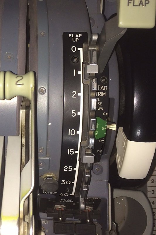
In the example (left) the aircraft has CWS engaged during climb following flaps retraction.  The FMA displays CWS R & CWS P, the vertical speed is 2650 and pitch mode is V/S after changing from TOGA thrust following climb out.  Pitch and roll follows the FD bars and speed is 240 KIAS with altitude set to flight level 20900.  If CWS remains engaged, the aircraft will continue at this attitude. 

Airspeed is not protected when using CWS. 

Following rotation, the Flight Director (FD) bars will be followed maintaining V2+15/20 until Acceleration Height (AH) is reached.  At AH, the MCP speed will be increased to climb speed, or to a speed as required by Air Traffic Control.  As airspeed increases the flaps will be retracted.  When the flaps are retracted, the control column will be placed in a position that correlates to the Flight Director bars and CWS A or B will be engaged – the attitude of the aircraft will now be fixed.  

The aircraft, in TOGA thrust, will maintain the established pitch as it ascends to the altitude set on the MCP.  TOGA thrust is speed protected; therefore, as long as the FD bars are followed there will not be a speed incursion.  If a roll mode is selected, the navigational data provided by this mode is also promulgated to the Flight Director.  Once the desired altitude has been reached, LNAV / VNAV can be engaged.

Whether a flight crew used CWS is personal preference.  Some flight crews use it regularly while others have never used it.

Turbulence (autopilot or CWS)

The Flight Crew Training Manual (FCTM) states:

‘That during times of turbulence the A/P system (CMD A/B) should be disengaged.’

When the aircraft is flying through turbulence, the autopilot is attempting to maintain an attitude (pitch) that is based upon a predefined barometric pocket of air that is present at the altitude you are flying at.   In severe turbulence this pocket of air may not be stable and the autopilot will try to change altitude to match the changing barometric pressure.  At its worse, the autopilot may unexpectedly disconnect.

CWS provides a stable buffer in which the aircraft will maintain its position when flying through turbulence.  When CWS is engaged, it will maintain a preset attitude rather than the A/P attempting to match the attitude to changing barometric pressure.

Flight Crew Training Manuals differ in their content; each manual has been written with a particular airline.  Many virtual flyers duplicate the procedures followed by Ryanair.  This is because the documentation for Ryanair is relatively easy to find, and the policy of this airline is reasonably conservative.  As such, I have transcribed from the Ryanair FCTM the segment on the use of CWS during turbulence.

The Ryanair FCTM states:

‘Flight through severe turbulence should be avoided, if possible.  When flying at 30,000 feet or higher, it is not advisable to avoid a turbulent area by climbing over it unless it is obvious that it can be over flown.  For turbulence of the same intensity, greater buffet margins are achieved by flying the recommended speeds at reduced altitudes.  Selection of the autopilot Control Wheel Steering (CWS) is recommended for operation in severe turbulence’.

The recommended Ryanair procedures for flight in severe turbulence is:

  • Do not use Altitude Hold (ALT HLD) mode.

  • Target the airspeed to approximately 280 KIAS or 0.76 MACH, whichever is lower.

  • During severe turbulence there often will be large and often rapid variations in indicated airspeed.  Do not chase the airspeed.

  • Engage the Yaw Damper.

  • If the autopilot is engaged, use CWS position, do not use ALT HLD mode.

  • Disengage the Autothrottle (stops the autothrottle from hunting a desired airspeed)

  • Maintain wings level and the desired pitch attitude. Use the attitude indicator as the primary instrument. In extreme down and updraft conditions extreme attitude changes may occur.  Therefore, do not use sudden and excessive control inputs.  After establishing the trim setting for penetration speed, do not change the stabilizer trim.

Autothrottle Use

When CSW is engaged, the autothrottle should not be engaged.  The reason for this is because the autothrottle is coupled to the automation, and if there is a change in the aircraft's attitude there will be a corresponding change in engine thrust.

This said, I have spoken with several pilots who claim that they leave the autothrottle on when using CWS.  In some respects it depends on the severity of the turbulence encountered. 

Lazy Flying

Although not sanctioned by Boeing, some pilots use CWS as a 'lazy way' of flying, whereby they may establish the aircraft at a specific attitude and vertical speed with the autothrottle engaged.  As CWS is a sub-set of the autopilot system, trim control will still be controlled by the system and the aircraft will maintain the desired attitude until CWS is cancelled.

A Virgin First Officer has stated that, after takeoff and flaps retraction, she will often use engage CWS to climb to a specific altitude, then she will engage LNAV, VNAV and the autopilot. 

It's important to realise there are many ways, (although not sanctioned by Boeing or a specific airline policy) to fly the Boeing 737 aircraft.

Important Point:

  • There is no speed protection when CWS is engaged, except when the aircraft is in TOGA mode.

Technical Data (general)

The Flight Crew Training Manual states:

‘After autopilot engagement, the airplane may be manoeuvred using the control wheel steering (CWS) pitch mode, roll mode, or both using the control wheel and column. Manual inputs by the pilot using CWS are the same as those required for manual flight. Climbs and descents may be made using CWS pitch while the roll mode is in HDG SEL, LNAV or VOR/LOC. Autopilot system feel control is designed to simulate control input resistance similar to manual flight.'

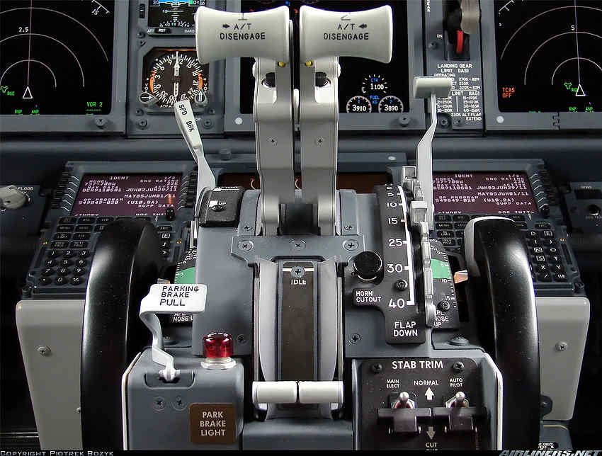
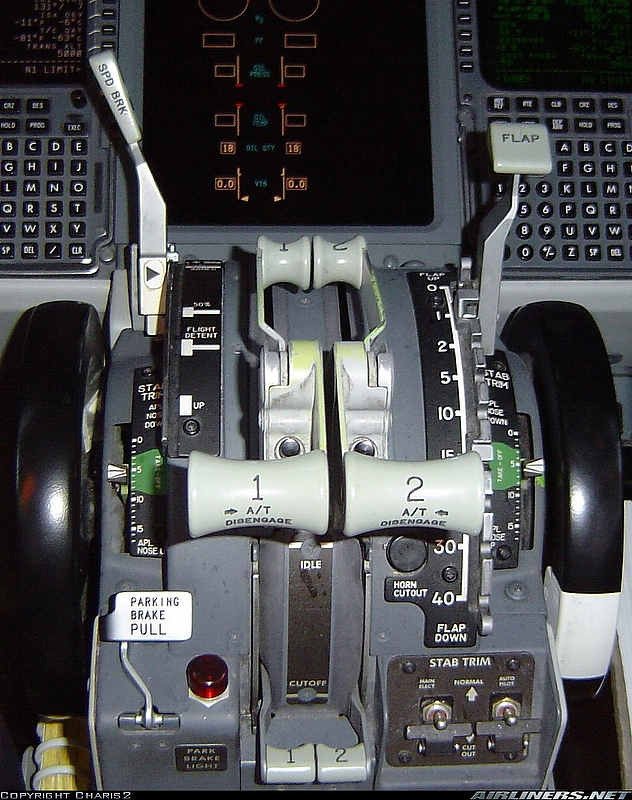
The Mode Control Panel (MCP) has two CWS buttons located on the First Officer side of the MCP beneath the two CMD buttons (CMD A/B).  Like the autopilot, CWS has a redundancy system (system A or system B).  By default the CWS system is off (annunciator is not illuminated). 

The CWS system has been designed so it can be used with or without the autopilot.

To engage the CWS system, either of the two CWS buttons must be pressed.  When engaged, the CWS annunciator will illuminate green and the Flight Mode Annunciator (FMA) on the Primary Flight Display (PFD) will annunciate CWS P and/or CWS R.

CWS cannot be engaged when any of the following conditions are met:

  • Below 400 feet.

  • Below 150 feet RA with the landing gear in the down position.

  • After VOR capture with TAS 250 kt or less.

  • After LOC capture in the APP mode.

Important Points:

  • CWS can only be engaged when there is no pressure on the flight controls. 

  • CWS can be engaged with the autopilot engaged or not engaged.

Operation - What CWS Does

As mentioned, the CWS system can be used with or without the autopilot being engaged. 

CWS can be engaged two ways.  Either by moving the control column when the autopilot is engaged, or by pressing the CWS button on the MCP.

To use CWS in its own right, the autopilot must be disengaged.  This can be done manually by pressing the CMD button or by pressing CWS; the later will disconnect the autopilot (the CMD annunciation will extinguish and the CWS annunciation will illuminate).   To access the CWS system partially, and still use the autopilot, the control column is moved (pitch/roll) while the autopilot is engaged.

Although the CWS concept is easy to understand, documenting exactly what it does is difficult and this can cause confusion.  I wouldn't become too concerned with the 'technical jargon' below, as CWS is easy to master by using the function and remembering what it does:

The following information has been edited from documentation acquired from Smart Cockpit Airline Training.

1:  CWS selected - PITCH and ROLL   (autopilot not engaged)

  • Depressing the CWS button on the MCP engages the autopilot pitch and roll axes in the CWS mode.  It also displays CWS-P and CWS-R on the FMA on both the Captain and First Officer Primary Flight Displays (PFD).  (Note that CMD is not selected and the CMD annunciation is extinguished on the MCP).

  • With CWS engaged, the autopilot maneuvers the aircraft in response to control pressures applied to the control wheel or column.  The control pressure is similar to that required for manual flight.  When control pressure is released, the autopilot holds existing attitude and roll.

•    If the column pressure is released with a bank angle 6 degrees or less, the autopilot rolls the wings level and holds existing heading. This feature is inhibited when any of the following conditions are met:

(i)     Below 150 ft RA with the landing gear down;

(ii)    After F/D VOR capture with TAS 250 kt or less; and,

(iii)   After F/D LOC capture in the APP mode.

2:  Moving control column - PITCH  (autopilot engaged)

  • The FMA will display CWS-P.

The pitch axis engages in CWS while the roll axis is in CMD when:

(i)     The autopilot pitch has been manually overridden with control column force and the  force required for override is greater than normal CWS control column force.  Note that manual pitch override is inhibited in the APP mode with both autopilots are engaged (autoland).

Important Points:

  • When approaching a selected altitude in CWS-P with the A/P in CMD, CWS-P changes to ALT ACQ and, when at the selected altitude, ALT HOLD engages.

  • If pitch is manually overridden while in ALT HOLD at the selected altitude, ALT HOLD changes to CWS-R If control force is released within 250 ft of the selected altitude, CWS-P changes to ALT ACQ and the autopilot returns to the selected altitude and ALT HOLD engages.  If the elevator force is held until more than 250 ft from the selected altitude, pitch remains in CWS PITCH.

3:  Moving control column - ROLL  (autopilot engaged)

•    The FMA will display CWS-R.

The roll axis engages in CWS while the pitch axis is in CMD when:

(i)     The pitch has been manually overridden with control column force and the force required for override is greater than normal CWS control column force.  

Important Point:

  • With CWS-R selected and the autopilot engaged, the aircraft will capture a selected radio course while the VOR/LOC or APP mode is armed. Upon intercepting the radial or localizer, the F/D and autopilot annunciation changes from CWS-R to VOR/LOC engaged and the autopilot tracks the selected course.

Using CWS (with the autopilot engaged) - Simplified

This segment has been added in response to some readers who stated they had difficulty in understanding some of the above content.  I hope it explains, in easier terms, how the CWS system can be used when the autopilot is engaged.

Moving the flight controls (pitch/roll) during automated flight will cause the CWS system to engage.  However, the autopilot (CMD) will remain selected and the CMD annunciator will remain illuminated on the MCP. 

Flying the aircraft in this manner can be useful when hand flying an approach, but wishing to follow the automated inputs from the ILS and/or FMC.

During such a procedure the following will be noted:

Moving flight controls left or right (roll):

(i)      The autopilot annunciation will remain illuminated;

(ii)     The FMA on the PFD will alter from CMD to CWS-R;

(iii)    The AFDS will illuminate A/P P/RST; and,

(iv)    The heading annunciation on the MCP will extinguish, as will the LNAV annunciation if engaged.

The aircraft can now be flown using control wheel steering.  To return to fully automated flight, press the heading button on the MCP.  LNAV, if used, will also need selecting.

Moving flight controls up or down (pitch):

(i)      The autopilot (CMD A/B) annunciation will remain illuminated;

(ii)     The FMA on the PFD will alter from CMD to CWS-P;

(iii)    The AFDS will illuminate A/P P/RST; and,

(iv)    The heading annunciation on the MCP will extinguish, as will LNAV annunciation if engaged.

Important Point:

  • If the pitch is altered to cause the aircraft to ascend, the altitude window in the MCP must be changed to the new altitude prior to moving the flight controls (altitude capture is automatic).  This is not required if the pitch is changed to cause the aircraft to descend.

Final Call

The use of CWS is very much underused and under-appreciated - whether used as a stand-alone system, or in conjunction with the autopilot.

Although surface control loading in a simulator rarely matches that of a real aircraft, the use of CWS in a simulator environment can still have positive benefits equating to better aircraft handling, especially when flying circuits and flying in turbulence.

  • NOTE:   This article has been rewritten to aid in clarity (28 November 2021).

MIP Improvement - Non-Reflective Displays

Currently the simulator is installed in a spare room in the house.  The room is well lit during the day and has windows on two sides opening to the garden.  Until a dedicated room is constructed in a windowless room in basement, this will be the home of the simulator.

Reflections - Mirror Mirror On The Wall.......

One aspect that was problematic (at least to me) was that the MIP comes standard with 1.5 mm thick reflective perspex to cover each display.  Reflections were a problem in the well lit room during the day and only eased somewhat during the evening hours.  From the left hand seat it was almost impossible to read the FO's MPD or ND display.  I also tired of seeing my reflection on the Captain's display.

Three Options

I investigated the option of non-reflective glass, however, 1.5 mm thick glass is very thin and the chance of glass breakage during installation or use quite real.  Further, non-reflective glass does not work optimally if there is more than a few millimeters gap between the display screen and the glass.  The next option was either an adhesive-type material, which I discarded as I dislike applying "sticky" things to glass or perspex. or non-reflective acrylic.

The only clear acrylic I could find locally that was non-reflective and 3 mm in thickness; a little thick as the standard perspex used by FDS  is 1.5 mm thickness.  I experimented with the  3mm acrylic on the smaller gauges (flaps, yaw and brake pressure).  The thickness didn't appear to present a problem, however, the thickness when used on the main displays and EICAS did present an issue; the screws were now to short to attach the display frame correctly.

The Solution

The solution is obviously to purchase thinner acrylic, however, this is not obtainable at the moment.  I solved the situation by using a beveling machine and cutting the lip edge of the acrylic that sits on the MIP (the area covered by the display frame) to 1.5 mm.  Therefore, the edge of the frame is 1.5 mm in thickness whilst the the actual display portion in front of the display has a thickness of 3 mm.

The Outcome

The reflections are now gone, the displays are bright and readable across the MIP, and I finally can fly during the day without seeing myself in a mirror.

B737 NG Display Unit Bezels By Fly Engravity

The bezels that have replaced the acrylic bezels made by FDS. The landing gear, clock annunciators (korrys) and brake pressure gauge are OEM parts converted for flight simulator use - First Officer side. Note OEM Korrys and clock

I recently upgraded the display unit bezels (frames) on the Main Instrument Panel (MIP).  

The previous bezels, manufactured by Flight Deck Solutions (FDS), lacked the detail I was wanting.  Increasingly, I found myself being fixated by glaringly incorrect hallmarks that did not conform to the original equipment manufacturer (OEM) – in particular, the use of incorrectly positioned attachment screws, the lack of a well-defined hinge mechanism, and the use of acrylic rather than aluminum.

Although it is not necessary to have replicated items that conform to a real part, it does add to the immersion level, especially if you are using predominately OEM parts.  The MIP in my case is a skeleton on which to hang the various real aircraft parts that have been converted for flight simulator use. 

This is not a review, but more a reason to why sometimes there is a need to change from one product to another.

The OEM display is a solid unit that incorporates the avionics, display and bezel in the one unit.  This unit has the protective plastic attached to the screen

OEM Display Units

The OEM display units used in the Boeing Next Generation airframes comprise a large rectangular box that houses the necessary avionics and glass screen for the display.   

The display unit is mounted by sliding the box into the MIP along two purpose-built sliding rails.  The unit is then locked into the MIP by closing the hinge lever and tightening the thumb screw on the lower right hand side of the bezel.  The hinge mechanism is unique to the OEM unit in that once the thumb screw is loosened; one side of the lower display adjacent to the hinge becomes a lever in which to pull the unit free of its locking points in the MIP.

The units are usually manufactured by Honeywell.

The display unit is one piece which incorporates the bezel as part of the assembly; therefore, it is not possible to obtain just the bezel – this is why a reproduction is necessary.

Reproduction Bezels

Reproduction bezels are manufactured by several companies – Open Cockpits, SimWorld, Fly Engravity and Flight Deck Solutions to name a few.  As with all replica parts, each company makes their products to differing levels of accuracy, detail and quality.

I looked at several companies and the closest to the  OEM item appeared to be the bezels manufactured by Fly Engravity and CP Flight (CP Flight are a reseller of Fly Gravity products).  

The main reasons for changing-out the FDS bezels were as follows:

  • FDS bezels have two Philips head screws in the upper left and right hand side of the bezel.  These are used to attach the bezel to the MIP.  The real bezel does not have these screws.

  • FDS bezels are made from acrylic.  The bezels in the real B737, although part of a larger unit, are made from aluminum.  Fly Engravity make their bezels from aluminum which are professionally painted with the correct Boeing grey.  

  • FDS have not replicated the hinge in the lower section of the bezel.  Rather, they have lightly engraved into the acrylic a facsimile of the hinge .   Fly Engravity fabricate a hinge mechanism, and although it does not function (there is absolutely no need for it to function) it replicates the appearance of the real hinge.

  • FDS use 1mm thick clear Perspex whereby the real aircraft uses smoke grey-tinted glass.  Fly Engravity bezels use 3 mm smoke grey-tinted Perspex.

  • The Perspex used by FDS is very thin and is attached to the inside of the bezel by double-side tape.  The thinness of the material means that when cleaning the display it is quite easy to push the material inwards which in turn breaks the sticky seal between the Perspex and the inside of the bezel.  Fly Engravity use thicker Perspex that is attached to the inside of the bezel by four screws.  It is very solid and will not come loose.

Table 1 provides a quick reference to the assailant points.

Detail showing the hinge mechanism in the Fly Engravity bezel.  Although the hinge is non-functional, the detail and depth of the cut in the aluminium frame provides the illusion of a functioning hinge mechanism

Attaching the Bezels to the FDS MIP

The FDS and Fly Engravity bezels are identical in size; therefore, there is not an issue with the alignment of the bezels with MIP – they fit perfectly.

Attaching the Fly Engravity bezels to the FDS MIP is not difficult.  The Fly Engravity bezels are secured to the MIP using the same holes in the MIP that were used to secure the FDS bezels. However, the screws used by Fly Engravity are a larger diameter; therefore, you will have to enlarge the holes in the MIP.  

Detail of the hinge thumb knob on the Fly Engravity bezel.  Although the internal screw is missing from the knob, the cross-hatched pattern on the knob compensates.  The knob is screwed directly into the aluminium frame and can be loosened or tightened as desired.  The circular device is a facsimile of the ambient light sensor (

For the most part the holes align correctly, although with my set-up I had to drill two new holes in the MIP.

The Fly Engravity bezels, unlike the FDS bezels, are secured from the rear of the bezel via the backside of the MIP.  The bezel and Perspex have precut and threaded holes for easy installation of the thumb screws.

Cross section of the Fly Engravity bezel showing the detail of the Perspex and attachment screw

Upgrade Benefits - Advantages and Disadvantages

It depends – if you are wishing to replicate the real B737 MIP as much as possible, then the benefits of upgrading to a Fly Engravity bezel are obvious.  However, the downside is that the aluminum bezels, in comparison to acrylic-made bezels are not inexpensive.

The smoke grey-tinted Perspex has definite advantages in that the computer monitor screens that simulate the PFD, ND and EICAS appear a lot sharper and easier to see.  But a disadvantage is that the computer monitors colour calibration alters a tad when using the tinted Perplex.  This is easily rectified by calibrating your monitors to the correct colour gamut.  I was concerned about glare and reflections, however, there is no more using the tinted Perspex than there is using the clear Perspex.

The Fly Engravity bezels have one minor inaccuracy in that the small screw located in the middle of the hinge thumb knob is not simulated.  This is a small oversight, which can be remedied by having a screw fitted to the knob.

Improvements

A possible improvement to the Fly Engravity bezels could be to use flat-headed screws, or to design a recessed head area into the rear of the Perspex (see above photograph which shows the height of the screw-head).  A recessed area would allow the screw head to sit flush enabling the monitor screen to be flush with the rear of the Perspex. 

The inability of the monitor screen to sit flush with the Perspex does not present a problem, but it is good engineering for items to fit correctly.

Final Call

Although the bezels made by FDS do not replicate the OEM item, they are still of good quality and are functional.  However, if you are seeking authenticity and prefer an aluminum bezel then those produced by Fly Engravity are superior.

Endorsement and Transparency

I have not been paid by Fly Engravity or any other reseller to write this post.  The review is not endorsed and I paid full price for the products discussed.

Glossary

  • EICAS – Engine Indicator Crew Alert system.

  • MIP – Main Instrument Panel.

  • ND – Navigation Display.

  • OEM – Original Equipment Manufacturer (aka real aircraft part).

  • Perspex - Poly(methyl methacrylate), also known as acrylic or acrylic glass as well as by the trade names Plexiglas, Acrylite, Lucite, and Perspex among several others.

  • PFD – Primary Flight Display.