Assembly of Forward Overhead Panel

Forward overhead using OEM parts

Construction of the simulator began in 2011.  It is now 2016 and I am perplexed to why the build has taken so long to complete.   Of course, opting to try and use OEM (Original Equipment Manufacture) parts whenever possible has added significant time to the project - especially the procurement of parts.

Most of the parts that make up the forward overhead have now been obtained and assembly of the components is well advanced.   Very soon the wiring from the panels to the Phidgets cards will begin.  This will be followed by several hours of testing to check correct functionality and to ensure perfect harmony between components and systems. 

A basic frame has been constructed to enable the overhead to be easily positioned to enable the wiring to be done with a little more ease.  After the forward overhead is completed, work on the aft overhead will commence.  Rome, it seems, was not built in a day.

Certainly, completion of the forward overhead will be the major project over the next few months.

FS-FlightControl Instructor Operating Station (IOS) - Review

Opening screen for FS-FlightControl IOSon the server computer.  IOS can be easily configured to automatically open after Windows start-up

Virtual flyers can be grouped into three broad groups.  Those that are satisfied using a desktop simulator, those that gravitate toward a professional simulator, and those that strive to replicate, as close as possible, a Level D simulation.  No matter which group you belong, there is a requirement for a feature-rich, reliable, and stable Instructor Operator Station (IOS).

This post will introduce the Instructor Station FS-FlightControl, developed by AB-Tools GmbH, a company located in Germany.  The review is not meant to be comprehensive as such a document would be as long as the product’s operating manual.  Rather, we will examine some of the product’s features prior to making an assessment of the software’s reliability and ease of use.

What is IOS - Do I need It

IOS is an acronym for Instructor Operating Station.  At its simplest, it's the menu system in Flight Simulator that enables you to choose from several parameters to create a pre-programmed flight scenario. 

A dedicated instructor station is far more than a few options to alter the time, place, and scenario in the simulator.  A good instructor station should enable you to set basic flight scenarios, in addition to being able to monitor set tasks and parameters.  The software should provide clear and readable displays, be set out logically, be easy to operate, and also be able to initiate system failures.  Furthermore, the software must be stable, reliable and consistent in its output.

There are several Instructor Operating Stations available on the market and most high-level avionics suites come with a ready-made IOS as part of their software.  Therefore, the question must be asked - why is there a need to purchase a stand-alone IOS.  

Put bluntly, many generic instructor stations have been added at the back-end of an avionics suite.  These instructor stations can lack functionality, features, and ease of use.  Furthermore, their layout is often not optimal or configurable.

Screen shot showing the POSITION page display of IOS.  Note the easy to navigate menu at the bottom area of the screen (twelve modules).  This menu system is available on allIOS pages and enables quick and easy navigation between modules

IOS Features - FS-FlightControl

The features and functionality that are supported by IOS are extensive, however, bear in mind that the instructor station has been designed to operate across different simulator platforms and avionics suites; not every feature may operate with the intended avionics suite.  For example, flight plans can be generated and sent to FSX in the standard .pln format, but they cannot be send directly to ProSim-AR in the correct format (as at the time of writing).

I have purposely not duplicated what has already been written on the FS-FlightControl website.  The website provides a well detailed description of the features and functionality of the software and includes numerous screen shots.

Broadly speaking, IOS has been developed around 12 main modules.  Like-minded themes have been grouped into whatever module is specific to the subject.  If the information exceeds what can be displayed on one page, then one or more sub-pages (sub-tabs) are provided.  There is a gamut of features

Main Modules

Position:   Aircraft re-position, runway preference, aircraft scenario, approach presets, airport selection and re-position options.

Map:   Street map, satellite map and height map.   Navaids, AI aircraft, weather, aircraft location, compass and route/flight plan overlay.

Flight Planing: Route and flight plan generation with load tool.  Importing and exporting of data with flight plan generated onto roving MAP.

Conditions:   Environmental conditions relating to weather (artificial and real-time), visibility (CAT presets), winds, clouds, precipitation, altitude levels, barometric pressure, presets, time and season, accelerated time, and user-generated conditions.  This section is very detailed and is examined in several sub-tabs.  Many of the presets are as easy as clicking a button on the screen.  For example, ILS visibility conditions can be generated by clicking one of the CAT buttons (CAT I, II, III, IIIa/b/c).

Push back:   Graphical interface enabling push back of aircraft at any angle and distance.

Fuel/Load:   Fuel volume, passenger, crew and cargo weights, aircraft weights (ZFW), center of gravity (%CG) and load tool.

View/Slew:   Alters external camera views of aircraft and enables the slewing of aircraft.

Failures:   Aircraft system failure conditions that can be triggered immediately, at pre-defined times, or at random.

Statistics:   Approach statistics - Graphical representation of aircraft in relation to vertical and lateral position, aircraft position, ground altitude, vertical speed, pitch, and bank angle.  Results can be exported to Google Earth for further analysis.

Network:   Module to control all computers and software within your simulation network (server and any number of client computers).

Aircraft:   Selectable list of aircraft options re: altitude, speed, direction, radios, TCAS alert status, engine parameter outputs, throttle outputs, autopilot, light and switches, etc. 

Settings:   Customization of all aircraft, map, and program parameters: colours, fonts, map layouts, etc.  Additionally, other variables can be customised such as CAT visibilities and decision heights.

Favoured Features

I’ll be honest, the more I use IOS the more I enjoy my simulation experience.  At the very least, IOS provides a reliable way to store various approach scenarios to numerous airports at different times, seasons and weather conditions.   Granted, that this can be done from the flight simulator menu, however, it cannot be done as cleanly nor as quickly as it can from the IOS module.

Although I do not use all the features available in the program, there are several that I continually use.  It is these I will discuss in further detail.

POSITION:  Position refers to the position of the aircraft whether it be on the ground or in the air.  IOS enables the user to select from several ground positions such as the gate, runway, terminal, base approach, straight-in approach, etc. A click of the mouse will position your aircraft to any of several preset locations. 

I find this to be a very good time saver, especially if you do not want to simulate a long taxi or some other part of the flight but wish to concentrate only on one aspect – such as the approach phase.  In addition to various presets, this page also allows customized approaches to be generated and saved.

Another aspect of this page deserves mention; the ability to select a chosen aircraft livery, parameter list (fuel state, trim, radio frequencies, etc) and save this to custom-named 'slot'.  This is another time-saving feature and easy method to choose a pre-saved livery of an aircraft type.

STATISTICS:   For those who fly by the numbers and want to improve their approach techniques, the statistics section provides a graphical interface that records the vertical and lateral deviation of the approach.  It also records airspeed, vertical speed and several other characteristics.

CONDITIONS:   Conditions broadly refers to environmental and weather conditions at the airport selected, or at various pre-selected waypoints or weather stations.  Changing weather conditions, visibility, season and time is as easy as clicking a button.

This page is exceptionally feature-rich and the instructor station can generate live weather, weather from an imported METAR string or any number of pre-saved weather themes.  For those interested in setting up specific weather events, for flight training, it is very easy to do so.  

Screenshot showing MAP display page.  Many advanced features that can be displayed as a map overlay.  The tabs along the sides of the page can be clicked to turn features on or off

MAP:  The map is a hidden gem that enables you to overlay a wealth of information onto a street or satellite map of the area of operation. 

For example, the user aircraft and AI aircraft are graphically represented along with all navigation aids which includes VORS, NDBs, high and low jetways, ILS feathers and waypoints.  Wind direction and current barometric pressure can also be displayed along with the current SID, STAR or route.  Whilst on the ground all aprons, runways and taxiways are shown.  Navigating to an assigned runway could not be easier as the user aircraft icon shows the position of the aircraft at all times. 

As with all windows, the MAP can be displayed as a separate screen on another monitor.  Therefore, it is possible to have IOS open on two monitors with one monitor showing the MAP view while the other monitor displays a different view.

An added advantage is the ability to position your aircraft anywhere on the map and create a position fix along with altitude, direction, pitch, bank, airspeed and radio frequencies.  This information can be saved for future activation from the POSITION page.  This enables you to quickly and easily set-up an approach and save this approach for future use.

For those that fly on-line, VATSIM, IVAO and PilotEdge are supported.

NETWORK: IOS enables the user to program the software to control what programs open or close on any computer that is connected to the network.

For example, I use a batch file  to open and close flight simulator, ProSim-AR and other FS related programs (weather, flight analysis, etc).  IOS when turned on from the client will automatically execute the opening of the batch file on the server computer.  Likewise, when triggered, IOS will engage the batch file I use to close flight simulator and other ancillary programs.  Additionally, a time delay can be configured to cause a delay between the closure of programs and the turning off of the server computer.  

Screenshot showing the PUSH BACK display page

Installation of IOS - Server and Client

The software package is downloaded from the developer’s website and consists of a self-extracting .exe file. 

As IOS has networking capability, it's not necessary to install IOS to the computer that has flight simulator installed; it will operate on a client computer.  Additionally, a wizard is used to direct you through the installation process and configuration.  Networking to a client is done via SimConnect.  FSUPIC and WideFS are not required.

Although networking is achieved through the use of SimConnect which can, at times, be problematic, I did not experience any issues.

Configuration

Configuring the program to suit your requirements is done from the SETTINGS page.  Variables can be altered for each aircraft, and aircraft profiles can easily be created that save particular parameters or conditions.  Likewise, the software can be altered to enable a particular font style and colour to be displayed along with a zoom value and size.  The process is straightforward.

Pretty much everything in IOS is able to be configured to your liking.

One aspect of IOS I found to be very handy, was that when you close the instructor station it will keep the last known settings.  This means the parameters for the next flight session (if not altered) will be identical to the last.

Ease of Use

Screenshot showing the FAILURES display page.  Note the open conditions call-out box.  There are several sub-pages (sub-tabs) that deal with failures.  Failures are an important asset to enthusiasts striving for realism

The IOS program is set-out intuitively and the various pages (modules) follow a logical sequence with like-minded themes bundled together on the same page.  The twelve page main menu located at the bottom of each page is promulgated across all pages and enables quick access to various features. 

Unlike other instructor stations, all information relating to a specific theme is located on the one main page (for example, failures or position page); it is not necessary to navigate between several pages trying to find the information.  Furthermore, the screen display can resized to either fill your display or only part fill it.

Another advantage is the implementation of large-style buttons that enable quick and accurate identification of a module.  Everything is easy to find and access.

Program Administration

Program administration encapsulates the opening and closing of programs from one or multiple computers. 

Without an instructor station or the use of batch files, several programs must be opened on the client and server computer to begin a flight.  This takes time and the process can be unwieldy.

If the instructor station is configured correctly, it is a two-step process to begin a flight.  First the computers must be turned on.  Second, from the client the FS-ControlControl IOS icon is depressed.  Once IOS opens on the client computer it will communicate with the server computer (via SimConnect) and open any number of programs on the server (assuming they have been configured correctly in the IOS NETWORK page).  

Once Flight Simulator opens and you are on the flight line it’s only a matter of using the instructor station to alter any variables particular to the flight (airport, aircraft position, weather, fuel, weight, etc).  All changes are automatically promulgated across the network to Flight Simulator.

The important aspect to note, is that other than turning on the server and client computers, everything is done from the one screen on the client computer using the one mouse/keyboard.  Likewise, when closing the simulator session everything can be done, including turning off the server computer, from the instructor station.

Cross-Platform Operations

The IOS operates with Microsoft Flight Simulator X (FSX/FS10) including Steam Edition, and with Lockheed Martin Prepar3D® 1.x, 2.x and 3.x. in a Windows environment.  A separate APP is available for Android and Apple (iOS).  The software works traditionally using the keyboard and mouse in addition to being optimized for touch screens.  IOS can be run either on the computer that has Flight Simulator installed or from a networked client computer.

Stability and Speed

The last thing anyone wants is a crash to desktop caused by a bug-ridden piece of software that exhibits stability issues, poor performance, and does not operate consistently.  

The stability of the instructor station is excellent.  In my simulator set-up the IOS is installed on a client computer and networked to Flight Simulator located on a server computer.  The software loads quickly and interacts with the simulator seamlessly.  

The speed at which software interacts with Flight Simulator is important and it’s pleasing to note that IOS commands do not exhibit any significant time lag between the client and server computers.  There is no time lag when switching between any of the interface screens on the instructor station.  Surprisingly, this includes the MAP mode.  Often a high definition map with several overlays cannot generate its resultant map within an acceptable time. 

This said, internet connection speed may cause users to experience different speeds.

The time taken to open the instructor station from the icon on the client computer is approximately 10-15 seconds.

Screenshot showing the CONDITIONS display page.  This page has several sub-pages that deal with conditions.  For example, real weather, presets, season, ILS visibility and accelerated time.  Note the display box in the lower left side that shows the frame rates

Updates to IOS (Annual Fee)

The software developer is very proactive and software updates with improvements, minor fixes and new features are regularly provided free of charge.  

However, the update period is only for one year following purchase.  After this period has lapsed, an annual fee will need to be paid to enable future updates to be used.  The annual fee is only for updates, the original software will still function.

Do you need to update ?  If you are happy with what you have, then no.  However, if you are seeking specific functionality then an update may have this functionality.  A list showing the updates can be read in the INFO section of the software. 

The developer realizes that each person’s requirements for an instructor station is different, and as such, entertains ideas and suggestions for additional features or improvements from end-users.

Support

FS-FlightControl does not have a dedicated forum, however the developer replies promptly to all e-mails sent via the software help page.  

A benefit of sending e-mail directly from the software is that the log files from your system are automatically attached to any outgoing message.  This enables the developer to easily understand the issue, saves time in asking for further information, and leads to a faster resolution.

Dedicated Manual

A manual for any in-depth software is an absolute necessity.  It is pleasing to note that the developer has written a manual and does not rely on a forum to provide answers to common questions.

The manual, which reflects the latest software build, is accessed from the FS-FlightControl IOS website.  If necessary a .pdf is available on request.  

Additionally, the manual can also be accessed directly from the software.  Each page has several small question marks (?) that when clicked navigate the user to the appropriate help section in the manual.  If you find the questions marks unsightly, then they can be turned off from the SETTINGS page.

Software Trial

This review has only examined several of the features that the instructor station is capable of.  To enable a comprehensive examination of the software, IOS can be installed with full functionality (including any prospective updates) for a period of 14 days.  After this time has elapsed, the software will need to be purchased.

Final Call

Considering the scope of what an instructor station does and how it can be used to enhance the effectiveness of a simulator, there is little doubt that a good IOS is essential.    

I've spent considerable time using the FS-FlightControl IOS and although this review touches on but a few of the features of IOS, I believe this software to be superior to other contemporary products.   It certainly has enhanced how I use the simulator leading to a more enjoyable experience.

The IOS software and further information can be downloaded at FS-FlightControl IOS.

  • Please note I have no affiliation with FS-FlightControl.  I have not been provided with ‘free’ software, nor did I receive a discount in return for a favourable review.  The comments and recommendations I have made are my own.

  • Flight Simulator, in this article, refers to the use FSX/FS10.  I use the B737 avionics suite developed by ProSim-AR.

Update

Since this review there have been several updated releases that have implemented a number of new ideas and rectified shortcomings.

ProSim-AR users will be pleased that an update includes the ability to import and export flight plans to the ProSim-AR database as an .xml file (10 character file name).  The update also enables synchronisation with the FMS, and display of the flight plan on the IOS map.

VNAV 'Gotchas' - Avoiding Unwanted Level-Offs

One aspect of using VNAV during published instrument departures, arrivals, and approaches is that it can cause unnecessary level-offs. 

These level-offs can cause engines to spool needlessly, increase fuel cost and stagger a Continuous Descent Final Approach (CDFA) such as when executing  an RNAV approach. 

It is not only domestic airliners that must meet altitude constraints; military aircraft also  must meet the same requirements when landing at a non-military airport (click to enlarge).  Image is copyright xairforces.net.  For those interested in flying the Wedgetail, there is a model available for ProSim-AR users on their forum page.

To avoid this, and ensure that minimum altitude constraints are met, two techniques can be used.

METHOD 1Constraints Are Not Closely Spaced.

This technique is normally used when waypoints with altitude constraints are not closely spaced (in other words, there is a moderate distance between altitude constraints).

During climbs, the maximum or hard altitude constraints should be set in the Mode Control Panel (MCP).

Minimum crossing altitudes need not be set in the MCP as the FMC message function will alert the crew if these constraints cannot be satisfied.

During descent, the MCP altitude is set to the next constraint or clearance altitude, whichever will be reached first.

Immediately prior to reaching the constraint, when compliance with the constraint is assured, and when cleared to the next constraint, the MCP altitude is reset to the next constraint/altitude level.

METHOD 2: Constraints Are Closely Spaced.

Where constraints are closely spaced to the extent that crew workload is adversely affected, and unwanted level-offs maybe a concern, the following is approved:

For departures, set the highest of the closely-spaced constraints.

For arrivals, initially set the lowest of the closely-spaced altitude constraints or the Final Approach Fix (FAF) altitude, whichever is higher.

IMPORTANT: When using either technique, the FMS generated path should be checked against each altitude constraint displayed in the CDU to ensure that the path complies with all constraints.  Furthermore, the selection of a pitch mode other than VNAV PTH or VNAV SPD should be avoided, as this will result in the potential violation of altitude constraints.

To enlarge more on VNAV is beyond the scope of this post.  A future post will address this topic in more detail.

Crew Controls Automation - Not Vice Versa

However, the system is only as good as the knowledge of the person pushing the buttons.  It is very important that a flight crew control the automation rather than the automation control the flight crew. 

If VNAV begins to do something that is unplanned or unexpected, do not spend precious time ‘thinking about the reasons why’ – disconnect VNAV and use a more traditional method or hand fly the aircraft.  Then, determine why VNAV did what it did.  The most common comment heard in today's modern cockpits is ‘What is it doing now…

Final Call

VNAV is an easy concept to understand, but it can be confusing due to innumerable variables associated with vertical navigation.  VNAV is probably one of the more complicated systems that virtual and real pilots alike have to understand.  When using VNAV it is paramount to maintain vigilance on what it is doing at any one time, especially during descent and final approach.     Furthermore, it is good airmanship to always have a redundancy plan in place – a ‘what if’ should VNAV fail to do what was anticipated. 

The below article also discuss VNAV:

An interesting article concerning VNAV:

Acronyms and Glossary

  • CDU - Control Display Unit (aka FMC)

  • FAF – Final Approach Fix

  • FMC - Flight Management Computer

  • FMS - Flight Management System.  Supply of data to the FMC and CDU

  • Gotcha - An annoying or unfavourable feature of a product or item that has not been fully disclosed or is not obvious.

  • LNAV – Lateral Navigation

  • MCP – Mode Control Panel

  • NPA - Non Precision Approach

  • VNAV – Vertical Navigation

  • VNAV PTH – Vertical Navigation Path

  • VNAV SPD – Vertical Navigation Speed

RNAV Approaches

RNAV 07 L - one of several RNAV approach charts for Los Angeles International Airport (LAX).  The most important aspect of an RNAV approach is that it is a Non-Precision Approach (NPA).  Note the word GPS is written in the title of the approach plate

My previous post provided of overview on RNAV and RNP navigation.  This article will explain what a RNAV approach is, provide incite to the operational requirements, and discuss the approach.  I will also briefly discuss Approach Procedures and Vertical Guidance (APV) and RNP/ANP values.

The operational criteria for RNAV approaches is complicated and not easy to explain.  There are a number of RNAV approaches (often different for differing areas of the globe) and each is defined by the accuracy of the equipment used in the execution of the approach.  As such, this article is not all encompassing and I encourage you to read other technical articles available on this website and elsewhere.

RNAV Approaches - Background Information

The Global Positioning System (GPS) is the brand name owned by the US military.  Initially all RNAV approaches were GPS orientated, however, in recent years this has changed to include Global Navigation Satellite System (GNSS) applications.  GNSS applications are not owned (or controlled) by the US military.  As such, an RNAV approach chart uses the words GPS and GNSS interchangeably.

What is an RNAV Approach

The definition for an RNAV approach is 'an instrument approach procedure that relies on the aircraft's area navigation equipment for navigational purposes'.  In other words, a RNAV approach is any non ILS instrument-style approach that does not require the use of terrestrial navigation aids such as VOR, NDB, DME, etc. 

Rather than obtain navigational information directly from  land-based navigational applications, the aids for the approach are obtained from a published route contained within the aircraft's Flight Management System (FMS) and accessible to the crew through the Control Display Unit (CDU).   Broadly speaking, the  approach uses signals, that are beamed from navigational satellites orbiting the Earth, and compares this data with the information from the FMC navigation database.

All Boeing Flight Management Systems (FMS) are RNAV compliant and have the ability to execute an RNAV approach.

Important Point:

  • An RNAV approach is classified as a Non-Precision Approach (NPA).

Non-Precision Approaches (NPA)

Before writing further, a very brief overview of Non-Precision Approaches is warranted.

There are three ways to execute a Non-Precision Approach.

(i)   IAN (integrated Approach Navigation).   IAN is a airline customer option and makes a NPA similar to an ILS approach.  A separate article has been written that addresses IAN.

(ii)   Vertical Speed (V/S).  V/S is not normally used when flying a RNAV approach that uses positional information from the aircraft's database.  However, V/S can be used for other Non-Precision Approaches and to transition to a RNAV approach.

(iii)   VNAV (Vertical Navigation).  VNAV is the preferred method to execute an NPA (provided the approach is part of the FMS database). 

(iv)   LNAV (Lateral Navigation).  LNAV is mandatory for all approaches that are GPS/GNSS/RNP based.

RNAV Approach Types

The following are RNAV approaches:

(i)    RNAV (GPS) approach;

(ii)   RVAV (RNP) approach;

(iii)  RVAV (RNP) AR approach; and,

(iv)  RNAV (GNSS) approach.

The RNAV (GNSS) approach can further be sub-divided into an additional three possible types of approach, each identified by a different minima.  These approaches are:

(i)    RNAV (GNSS) LNAV;

(ii)   APV Baro VNAV approach;

(iii)  APV SBAS approach.

It's easy to become confused by the various types of RNAV approaches, however, the actual flying of a RNAV approach does not differ greatly between each approach type.  The main difference lies in the level of accuracy required for the approach to be flown.

Approach Procedures with Vertical Guidance (APV)

APV refers to any approach which has been designed to provide vertical guidance to a Decision Height (DH).  An APV approach is characterised by a constant descent flight path, a stable airspeed, and a stable rate of descent.  This type of approach rely upon Performance Based Navigation (PBN).

The difference between the two APV approaches (ii and iii mentioned above) is that an APV Baro VNAV approach uses barometric altitude information and data from the FMS database to compute vertical guidance.  in contrast the APV SBAS approach uses satellite based augmentation systems, such as WAAS in the US and Canada and EGNOS in Europe, to determine lateral and vertical guidance. 

I will now discuss the RNAV (GNSS & RNP) approach.

Flying The RNAV (GNSS) Approach

The RNAV (GNSS) approach is designed to be flown with the autopilot engaged.  The recommended roll mode is LNAV or HDG SEL.  The preferred method for pitch is VNAV.  If LNAV and VNAV are engaged, the aircraft will fly the lateral and vertical path as determined by the FMS database; the route is displayed in the LEGS page of the CDU.

The aircraft uses the FMS database to determine its lateral and vertical path.  As such, it is very important that the RAW data published in the navigational database is not altered by the flight crew.  Furthermore, the data presented in the CDU should be cross-checked with the data on the approach chart to ensure it is identical.

As discussed previously, an RNAV (GNSS) approach is classified as a Non-Precision Approach.  Therefore, minima is at the Minimum Descent Altitude (MDA).   It is good airmanship to add +50 feet to the MDA to reduce the chance of descending through the MDA.  If a RNAV (RNP) or APV approach is being flown, the minima changes from a MDA to a Decision Height (DH). Whatever the requirement, the minima will be annotated on the approach chart.

LIDO chart (Lufthansa Systems) depicting the RNAV (RNP) 01 approach into BNE-YBBN (Brisbane Australia).  Note that this chart has a Decision Altitude (DA) rather than a Minimum Descent Altitude (MDA).  Chart courtesy of NaviGraph

RNAV (RNP) Approaches

RNP stands for Required Navigation Performance which means that specific navigational requirements must be met prior to and during the execution of the approach.

There are two types of RNAV (RNP) approaches:

(i)   RNAV (RNP) approach; and,

(ii)  RNAV (RNP) AR approach.

Both approaches are similar to a RNAV (GNSS) approach, however, a RNAV (RNP) approach, through the use of various sensors and equipment, achieves far greater accuracy through the use of Performance Based Navigation (PBN), and can therefore be flown to a DA rather than a MDA.

RNP/ANP - How It Works

An RNAV (RNP) approach compares the position that the aircraft should be in with the actual position of the aircraft.  If this value exceeds the prescribed distance (RNP exceeds ANP), the approach must be aborted.    The use of RNP/ANP enables greater accuracy in determining the position of the aircraft.

RNP/ANP Alerts

If an anomaly occurs between RNP and ANP one of two RNP alerts will be generated:

(i)    VERIFY POSITION - displayed in the scratchpad of the CDU; or,

(ii)   UNABLE REQD NAV PERF-RNP - displayed on the Navigation Display (ND) (if EFIS is set to MAP). 

It should be noted that different versions of CDU software will generate different alerts.  This is because newer software takes into account advances in PBN.  To determine which software version is in use, press IDENT from the CDU main page (LSK1L) and check OP PROGRAM.  ProSim-AR uses U10-8a.

The variables for RNP/ANP can be viewed in the CDU in the POS REF page (page 3), the LEGS page when a route is active, and also on the Navigation Display (ND).

A second type of RNP approach is the RNAV (RNP) AR approach.  This approach enables you to have curved flight paths into airports surrounded by terrain and other obstacles. Hence why special aircraft and aircrew authorization (AR) is required for these approaches.  Other than AR and additional flight crew training, the approach is identical to the RNAV (RNP) approach.

Advantages of RNAV and RNAV (RNP) Approaches

The benefit of using an RNAV approach over a traditional step-down approach is that the aircraft can maintain a constant angle (Continuous Descent Final Approach (CDFA)) until reaching minima.  This has positive benefits to fuel savings, engine life, passenger comfort, situational awareness, and also lowers flight crew stress (no step-downs to be followed).   Additionally, it also minimises Flight Into Terrain (CFIT) events.

A further advantage is that the minimas for an RNAV approach are more flexible than those published for a standard Non-Precision Approach not using RNAV.  RNAV approach charts have differing descent minima depending upon the type of RNAV approach.

For example, if flying a RNAV (RNP) approach the MDA is replaced by a DH.  This enables a lower altitude to be flown prior to a mandatory go-around if the runway threshold is not in sight.  The reason that a RNAV (RNP) approach has a DH rather than a MDA (and its resulting lower altitude constraint) is the far greater accuracy achieved through the use of Performance Based Navigation (PBN).

Approach To Land Using RNAV

The following addresses the basics of what is required to execute an RNAV approach.

Prior to beginning the approach, the crew must brief for the approach and complete ant required preparation. This includes, but is not limited to, the following items:

(i)     Equipment must be operational prior to starting the approach;

(ii)    Selection of the approach procedure, normally without modifications from the aircraft's navigation database (CDU);

(iii)    For airplanes without Navigation Performance Scales (NPS), the map display should be set to the 10 NM or less range.  This is to monitor path tracking during the final approach Segment and provide greater navigational awareness;

(iv)    For airplanes with NPS, the map display range may be set to whatever distance is desired;

(v)     TERR display must be selected on either the Captain or First Officer side of the ND;

(vi)     For airplanes without Navigation Performance Scales (NPS), the RNP progress page on the CDU should be displayed. For airplanes equipped with NPS, selection of the CDU page is at the crew's discretion;

(vii)    The navigation radios must be set according to the type of approach; and,

(viii)   There must be no alerts generated (UNABLE REQD NAV PERF and/or VERIFY POSITION).

In addition to the above, airline Standard Operational Procedures (SOPs) may require additional caveats.  For example, the setting of range rings on the ND to provide enhanced situational awareness at specific points (range rings can be set on the FIX page in the CDU).

Important Points:

  • Select the approach procedure from the arrivals page of the CDU and cross-check this data with that published on the approach chart, especially the altitude constraints and the Glide Path (GP).

  • If the Initial Approach Fix (IAF) in the CDU has an ‘at or above’ altitude restriction, this may be changed to an ‘at’ altitude restriction that uses the same altitude. Speed modifications (using speed intervention) are allowed as long as the maximum published speed is not exceeded. No other lateral or vertical modifications should be made at or after the IAF.

Beginning the Approach

Select LNAV no later than the IAF. If on radar vectors, select LNAV when established on an intercept heading to the final approach course. VNAV PTH must be engaged and annotated in the Flight Mode Annunciator (FMA) for all segments that contain a Glide Path (GP) angle, as shown on the LEGS page, and must be selected no later than the Final Approach Fix (FAF) or published glide path intercept point.

Speed Intervention (INTV), if desired, can be used prior to the GP.  Good airmanship directs that the next lower altitude constraint is dialled into the MCP altitude window as the aircraft passes through the previous constraint.  When 300 feet below the Missed Approach Altitude (MAA) re-set the altitude window in the MCP to the MAA.

Final Approach using RNAV

When initiating descent on the final approach path (the GP), select landing flaps, slow to final approach speed, and do the landing checklist. Speed limits published on the approach chart must be complied with to enable adequate bank angle margins. 

At minima, or as directed by the airline's SOP, the autopilot followed by the autothrottle is disconnected and a visual 'hands on' approach made to the runway threshold.

Once established on final approach, a RNAV approach is flown like any other approach.

Final Call

The Boeing aircraft is capable of several types of Non-Precision Approaches, however, outside the use of ILS and possibly IAN, the RNAV approach enables an accurate glide path to be followed to minima.  While it's true that the differing types of RNAV approaches can be confusing due to their close relationship, the approach is straightforward to fly.

This short article is but a primer to understanding an RNAV approach.  Further information can be found in the FCTM, FCOM and airlines SOP.

In my next article we will look some of the possible 'gotchas' that can occur when using VNAV.

References

Flight Crew Training Manual (FCTM), Flight Crew Operations Manual (FCOM) and airline SOP.

Acronyms and Glossary

  • Annunciator – Often called a korry, it is a light that illuminates when a specific condition is met

  • ANP - Actual Navigation Position

  • APV - Approach Procedure with Vertical Guidance

  • CFIT - Continuous Flight Into Terrain

  • DME – Distance Measuring Equipment

  • FAF - Final Approach Fix

  • FCOM - Flight Crew Operations Manual (Boeing)

  • FCTM - Flight Crew Training Manual (Boeing)

  • FMA - Flight Mode Annunciator

  • FMC – Flight Management Computer

  • FMS – Flight Management System

  • Gotcha- An unfavorable feature of a product or item that has not been fully disclosed or is not obvious.

  • GPS – Global Positioning System

  • GNSS - Global Navigation Satellite System

  • IAF - Initial Approach Fix

  • Korry - See annunciator

  • LNAV – Lateral Navigation

  • LPV - Localizer Performance with Vertical Guidance

  • MAA - Missed Approach Altitude

  • MCP – Mode Control Panel

  • ND – Navigation Display

  • NPA - Non Precision Approach

  • PBN - Performance Based Navigation

  • RNAV – Area Navigation

  • RNP - Required Navigation Performance

  • SOP - Airline Standard Operational Procedure.  A manual that provides additional information to the FCTM and FCOM

  • SBAS - Satellite based augmentation systems.  In the U.S. called WAAS and Europe called EGNOS.

  • VNAV – Vertical Navigation

  • VNAV PTH – Vertical Navigation Path

  • VNAV SPD – Vertical Navigation Speed

  • VOR – VHF Omni Directional Radio Range

  • Updated 11 November 2021

RNAV, RNP, LNAV and VNAV Operations - Overview

Collins Mode Control Panel (MCP) showing lnav and vnav buttons

New flyers to the Boeing 737NG often become confused understanding the various terminology used with modern on-board navigational systems.

Although the concepts are easy to understand, the inter-relationship between systems can become blurred when the various types of approaches and departures are incorporated into the navigational system.

This post will not provide an in-depth review of these systems; such a review would be lengthy, confusing and counterproductive to a new virtual flyer.  Rather, this post will be a ‘grass-roots’ introduction to the concept of RNAV, RNP, LNAV and VNAV.  I will also touch on the concept of Performance Based Navigation (PBN).

In the Beginning there was RNAV

RNAV is an acronym for Area Navigation (aRea NAVigation). 

Prior to complex computers, pilots were required to use established on-the-ground navigational aids and would fly directly over the navaid.  Such a navaid may be a VOR, NDB or similar device.  Flying over the various navaids was to ensure that the flight was on the correct route.  Often this entailed a zigzag course as navaids could not be perfectly aligned with each other in a straight line - airport to airport. 

When computers entered the aviation world it became possible for the computer to 'create' an imaginary navigation aid based on a direction and distance from a ground-based navaid.  Therefore, a straight line could be virtually drawn from your origin to destination and several waypoints could be generated along this line.   The waypoints were calculated by the computer based on ground VORs and positioned in such a way to ensure more or less straight-line navigation.

In essence, RNAV can be loosely defined as any 'straight line' navigation method similar to GPS that allows the aircraft to fly on any desired path within the coverage of referenced NAVAIDS.

Required Navigation Performance (RNP) and Performance Based Navigation (PBN)

Simply explained, Required Navigation Performance (RNP) is a term that encompasses the practical application of advanced RNAV concepts using Global Navigation Satellite Systems (GNSS).

However, there is a slight difference between RNP and RNAV although the principles of both systems are very similar. 

RNAV airspace generally mandates a certain level of equipment and assumes you have a 95% chance of keeping to a stated level of navigation accuracy.  On the other hand, RNP is performance based and requires a level of on-board performance monitoring and alerting.  This concept is called Performance Based Navigation (PBN).

RNAV and RNP both state a 0.95 probability of staying within 1 nm of course.  But RNP (through PBN) will let you know when the probability of you staying within 2 nm of that position goes below 0.99999.  In essence, RNP and PBN enable an aircraft to fly through airspace with a higher degree of positional accuracy for a consistently greater period of time. 

To achieve this level of accuracy a selection of navigation sensors and equipment is used to meet the performance requirements.  A further enhancement of this concept is the use of RNP/ANP (Required Navigation Performance and Actual Navigation Performance.  Advanced RNAV concepts use this comparative analysis to determine the level or error between the required navigation (the expected path of the aircraft) and the actual navigation (what path the aircraft is flying.)  This information is then displayed to the flight crew.

LNAV and VNAV

LNAV and VNAV are parts of the Flight Guidance System, and are acronyms for Lateral Navigation and Vertical Navigation'.  Both these functions form part of the automation package that the B737NG is fitted with.

LNAV is the route you fly over the ground. The plane may be using VORs, GPS, DME, or any combination of the above. It's all transparent to the pilot, as the route specified in the clearance and flight plan is loaded into the Flight Management System (FMS), of which the Flight Management Computer (FMC) is the interface.

The route shows up as a magenta line on the Navigation Display (ND), and as long as the LNAV mode on the Mode Control Panel (MCP) is engaged and the autopilot activated, the aircraft will follow that line across the ground. LNAV however, does not tell the plane what altitude to fly, VNAV does this.

VNAV is where the specified altitudes at particular waypoints are entered into the FMS, and the computer determines the best way to accomplish what you want.  The inputs from VNAV are followed whenever the autopilot is engaged (assuming VNAV is also engaged).  

The flight crew can, if necessary alter the VNAV constraints by changing the descent speed and the altitude that the aircraft will cross a particular waypoint, and the computer will re-calculate where to bring the throttles to idle thrust and begin the descent, to allow the aircraft to cross the waypoint, usually in the most economical manner.

VNAV will also function in climb and take into account airspeed restrictions at various altitudes and will fly the aircraft at the desired power setting and angle (angle of attack) to achieve the speed (and efficiency) desired.

There is not a fast rule to whether a flight crew will fly with LNAV and VNAV engaged or not; however, with LNAV and VNAV engaged and the autopilot not engaged, LNAV and VNAV will send their signals to the Flight Director (F/D) allowing the crew to follow the F/D cue display and hand fly the aircraft the way the autopilot would if it were engaged.

Reliance on MCP Annunciators

Flight Mode Annunciator (FMA) showing LNAV and VNAV Path Mode engaged.  The Flight Director provides a visual cue to the attitude of the aircraft while the speed is controlled by the FMC.  CMD indicates that the autopilot is engaged (ProSim737 avionics suite)

LNAV and VNAV have dedicated annunciators located on the Mode Control Panel (MCP).  These annunciators illuminate to indicate whether  a particular mode is engaged. 

However, reliance on the MCP annunciators to inform you of a mode’s status is not recommended.  Rather, the Flight Mode Annunciator (FMA) which forms part of the upper area of the Primary Flight Display (PFD) should be used to determine which modes are engaged.  Using the FMA will eliminate any confusion to whether VNAV (or any other function) is engaged or not.

This post explains the Flight Mode Annunciators (FMA) in more detail.

Final Call

RNAV is a method of area navigation that was derived from the use of VOR, NDBs and other navaids.  RNP through it use of GNSS systems has enabled Area Navigation to evolve to include LNAV and VNAV which are sub-systems of the Flight Guidance System -  LNAV is the course across the ground, and VNAV is the flight path vertically. 

Historically, navigation has been achieved successfully by other methods, however, the computer can almost always do things better, smoother and a little easier – this translates to less workload on a flight crew.  

In my next post, we will discuss RNAV approaches and how they relate to what has been discussed above.

References

The information for this article came from an online reference for real-world pilots.

Acronyms and Glossary

  • Annunciator – Often called a korry, it is a light that illuminates when a specific condition is met

  • DME – Distance Measuring Equipment

  • FMA - Flight Mode Annunciator

  • FMC – Flight Management Computer

  • FMS – Flight Management System

  • GPS – Global Positioning System

  • GNSS - Global Navigation Satellite System

  • LNAV – Lateral Navigation

  • MCP – Mode Control Panel

  • ND – Navigation Display

  • NPA - Non Precision Approach

  • PBN - Performance-based Navigation

  • RNAV – Area Navigation

  • RNP - Required Navigation Performance

  • VNAV – Vertical Navigation

  • VNAV PTH – Vertical Navigation Path

  • VNAV SPD – Vertical Navigation Speed

  • VOR – VHF Omni Directional Radio Range

Trim Wheel Nut Tool - New Design

The redesigned Trim Wheel Nut Tool. Fabricated from a solid piece of aluminium

A potential problem when using an OEM Boeing throttle unit, is removing the nut that secures the trim wheels to the side of the throttle.  The nut has been designed in such a way that loosening it can only be done with a specialised tool.  Attempting to use a screwdriver or pliers may burr the nut, or slip causing damage to the trim wheel.

In an earlier post I examined how a simple tool had been designed to easily remove the nut from the spline shaft that holds the trim wheels in place.   Although this tool was functional there was room for improvement in its design and manufacture.

New Design and Improved Engineering

The tool, has been redesigned and incorporates an aluminium cylinder that has been produced from a solid block of aluminium using a milling machine.  The inside of the cylinder has been milled and a set screw securely inserted.  The set screw mates with the screw that holds the spline shaft in place.

The outer flange, adjacent to the set screw has then been machined so that two ridges, approximately 1mm in height are either side of the set screw.  The set screw mates with the female located on the end of the spline shaft while the ridge provides extra purchase by mating with the indents in the nut. 

In addition, a circular hole 8mm in diameter has been drilled through the upper portion of the cylinder enabling a similar sized piece of metal, or the shaft of a screwdriver to be inserted.  This allows additional purchase and leverage should the nuts be difficult to loosen.   Finally, the aluminium on the outside of cylinder has been slightly scoured to facilitate better grip.

New design has easier mating which enables greater purchasing power for removing tight spline nuts

Round and Round

The trim wheels are continually rotating back and forth as the aircraft is trimmed.  This rotation causes the nut, that secures the trim wheels to the spline shaft to, over time, become tighter and therefore more difficult to loosen.  This firmness is often exacerbated if working on a throttle unit removed from a real aircraft, that has not had the spline nuts removed for several years; corrosion and caked grease can easily cement the nuts in place.

This tool, although not an OEM part, is more than adequate to loosen the most determined trim wheel nut.

Knobs Aren't Knobs - Striving for the Perfect Knob

The real item – a Boeing Type 1 General Purpose Knob (GPK) and issue packet.  There can be nothing more superior to an OEM part, but be prepared to shell out a lot of clams

In Australia during the early 1980s there was a slogan ‘Oils Ain't Oils’ which was used by the Castrol Oil Company.   The meaning was simple – their oil was better than oil sold by their competitors.  Similarly, the term ‘Knobs aren’t Knobs’, can be coined when we discuss the manufacture of reproduction knobs; there are the very good, the bad, and the downright ugly.

Boeing Knobs

As a primer, there are several knob styles used on the Main Instrument Panel, forward and aft overhead, various avionics panels, and the side walls in the 737-800 Next Generation. 

If you search the Internet you will discover that there are several manufacturers of reproduction parts that claim their knobs and switches are exactly identical to the OEM knobs used on Boeing aircraft – don’t believe them, as more often than not they are only close facsimiles.

In this article, I will primarily refer to the General Purpose Knobs (GPK) which reside for the most part on the Main Instrument Panel (MIP).  Boeing call these knobs Boeing Type 1 knobs.

oem 737 -800 next generation knob. note different location of set screw. knob used on overhead

Why Original Equipment Manufacturer (OEM) Knobs Are Expensive

Knobs are expensive, but there are reasons, be they not be very good ones.  

The average Boeing style knob is made from painted clear acrylic resin with a metal insert. On a production basis, the materials involved in their manufacture are minimal, so why do OEM knobs cost so much…   Read on.

There are two manufacturers that have long-term contracts to manufacture and supply Boeing and Airbus with various knobs, and both these companies have a policy to keep the prices set at an artificially high level.

Not all flight decks are identical, and the requirements of some airlines and cockpits are such that they require knobs that are unique to that aircraft model; therefore, the product run for knobs for this airframe will be relatively low, meaning that to make a profit the company must charge an inordinate amount of money to cover the initial design and production costs.

A high-end plastic moulding machine is used to produce a knob, and while there is nothing fancy about this type of technology and the process is automated, each knob still requires additional work after production.  This work is usually done by hand.

Cross section of a Boeing Type 1 General Purpose Knob

Once a knob has been produced, it must be hand striped and finished individually to produce a knob that is translucent and meets very strict quality assurance standards.  Hand striping is a complex, time consuming task. 

Additionally, each knob must undergo a relatively complex paint spraying procedure which includes several coats of primer and paint, and a final clear protective coating.  Spray too much paint and the translucent area (called the pointer) inside the twin parallel lines will not transmit light correctly.  Spray too little paint and the knob can suffer from light bleed.  There is a fine line during production when it is easy to ruin an otherwise good knob with a coat of thickly applied paint. 

Finally, any part made for and used by the aviation industry must undergo rigorous quality assurance, and be tested to be certified by the countries Aviation Authority.  Certifying a commercial part is not straightforward and the process of certification takes considerable time and expense.  This expense is passed onto the customer.

Often disregarded during the manufacture of reproduction knobs is the inner metal sleeve.  The sleeve protects the material from being worn out from continual use

Replicating Knobs - OEM Verses Reproduction

It’s not an easy process to replicate a knob to a level that is indiscernible from the real item.  Aside from the design and manufacture of the knob, there are several other aspects that need to be considered: functionality, painting, backlighting, robustness and appearance to name but a few. 

Backlighting and Translucency

To enable the knob to be back lit calls for the knob to be made from a translucent material.  Unfortunately many reproduction knobs fall short in this area as they are made from an opaque material.

The knob must also be painted in the correct colour, and have several coats of paint applied in addition to a final protective layer.  The protective layer safeguards against the paint flaking or peeling from the knob during normal use.  In the photograph below, you can see where extended use has begun to wear away part of the knob's paint work revealing the base material.

Detail of the grip and metal set screw.  The set screw is important as it enables the knob to be secured against the shaft of the rotary.  This knob previously was used in a Boeing 737-500

Set Screws and Metal Inserts

Often lacking in reproduction knobs is a solid metal set screw (grub screw).

The task of the set screw to secure the knob against the shaft of the rotary so that when you  turn/twist the knob it does not rotate freely around the shaft.  Plastic set screws can be easily worn away causing the knob to freely rotate on the shaft of the rotary encoder. 

The position of the set screws on the knob also deserves attention.  Correctly positioned set screws will minimize the chance of rotational stress on the shaft when the knob is turned.

Of equal concern is the hole on the underside of the knob where the rotary shaft is inserted.  The hole should be sheathed in metal.  This will increase the knob’s service life.  If the hole does not have a metal sheath, it will eventually suffer from wear (disambiguation) caused by the knob being continually being turned on its axis.   Finally, the knob must function (turn/twist) exactly as it does in the real aircraft.

Reproduction knobs may fail in several areas:

(i)    The knob has various flaws ranging from injection holes in the molded plastic to being the incorrect size or made from an inferior plastic material;

(ii)    The knob does not use metal set screws, and the set screws are not located in the correct position on the knob;

(iii)    The knob has a poorly applied decal that does not replicate the double black line on Next Generation General Purpose Knobs.  The adhesive may not be aligned correctly and may peel away from the knob;

(iv)    The knob is made from a material that does not have the ability to transfer light (translucent pointer);

(v)    The knob does not appear identical in shape to the OEM part (straight edge rather than curved);

(vi)    The paint is poorly applied to the knob and peels off.  OEM knobs have several thin coats of paint followed by hard clear coating of lacquer to ensure a long service life;

(vii)    The colour (hue) of the knob does not match the same hue of the OEM product; and,

(viii)    The circular hole in the rear of the knob, that connects with the shaft of the rotary encoder does not have inner metal sleeve.  

The time it takes to manufacture a knob is time consuming, and to produce a quality product, there must be a high level of quality assurance throughout the manufacturing process.

Older Classic-style Knobs

It's common knowledge that many parts from the classic series airframe (300 through 500) are very similar, if not identical to the parts used in the Next Generation airframe.  Unfortunately, while some knobs are identical most are not.

The knobs may function identically and be similarly designed and shaped, but their appearance differs.  Knobs used in the Next Generation sport a twin black-coloured line that abuts a translucent central line called the pointer, classic series knobs have only a central white line.

Rotary Encoders

Although not part of the knob, the rotary encoder that the knob is attached deserves mention.

An often quoted quib is that an OEM knob will feel much firmer than a reproduction - this is not quite true.  Whilst it is true that an OEM knob does has a certain tactile feel, more often than knot the firmness is caused by the rotary that the knob is attached to.

Low-end rotary encoders that are designed for the toy market are flimsy, have a plastic shaft, and are easy to turn.  In contrast, rotaries made for the commercial market are made from stainless steel and are firmer to turn.

Also, low end rotaries and knobs are made from plastic and with continual use the plastic will wear out prematurely resulting in the knob becoming loose.

Many reproduction knobs fit the bill, and for the most part look and feel as they should. It's easy to criticize the injected plastic being a little uneven along the edge, but this is unseen unless you are using a magnifying glass

Final Call

Whether you use reproduction or OEM knobs in your simulator is a personal choice; It doesn't play a huge part in the operation of a simulator.  After all, the knobs on a flight deck are exactly that – knobs.  No one will know you have used a reproduction knob (unless low end reproductions have been chosen).

However, the benefit of using a real aircraft part is that there is no second guessing or searching for a superior-produced knob.  Nor is there concern to whether the paint is the correct colour and shade, or the knob is the correct shape and design – it is a real aircraft part and it is what it is.  But, using OEM knobs does have a major set-back - the amount of money that must be outlaid.  

But, second-hand OEM NG style knobs are not easy to find and often there is little choice but to choose ‘the best of the second best’.

Increasing Paint Longevity - Avionics Panels

Testers Dullcote.  Although it can be applied by a brush, a better approach is to use an airbrush and spray a thin coat onto the panel. When applying Dullcote to a panel, it is best to spray an even thin coat

One of the most important items in a simulator is the panel; after all, you spend a lot of time looking at panels, and a scratch or major blemish can be rather off-putting.  

It is unfortunate, that the final grey-coloured coat of paint on many reproduction panels does not conform to the same level of quality assurance that Gables or Smiths provide on an OEM item. 

Some reproduction panels can easily be scratched and chipped, and after installing and removing a panel several times, or using it for a few months, the panel quickly can appear to look like a well-used item. 

Quality assurance is a term frequently used to discuss the quality of an item.  Many manufacturers of reproduction panels only apply one or two coats of paint which may or may not be applied over a primer.  The strength and longevity of the paint depends upon whether a primer has been used, the thickness of the paint, the quality of the paint and the number of applications.  Three thinly applied coats of grey-coloured paint over primer base is far better than one or two thick coats of paint without a primer. 

The final paint finish should not be shiny but be non-reflective.

So how can you improve the durability of paint after it has been applied? 

A product called Testers DullCote has been used in the modelling arena for many years.  Modelers apply a layer of Dullcoat to their models prior to applying other painting effects which may be damaging to the underlying base coat.   Dullcote dries to a clear matt texture that adds a layer of protection to the base coat of paint.  

The application of Dullcote can be either by rattle spray can, airbrush or by a standard modelling brush.  Whatever application method is chosen, always trial the product on a lesser item prior to applying to an expensive avionics panel.

If applied correctly, Dullcote will minimize the chance of a panel being scratched or blemished and provide a clear, durable, and flat texture that can easily be cleaned.  Additionally, if Dullcoat is applied to an OEM annunciator, the application will enhance the appearance of the annunciator making it appear clearer than possibly what it is.

Glossary

  • Gables and Smiths – Two manufacturers of OEM Boeing 737 avionics panels

  • Light Plate – The actual plate that contains the lighting array to backlight the cut-out sections on a panel

  • OEM – Original Equipment Manufacture aka real aircraft part

  • Panel – Used loosely to mean a avionics panel or module (for example Fire Suppression Panel or radio panel)

BRT / DIM Functionality - Lights Test Switch

Lights Test switch.  The three way switch located on the Main Instrument Panel (MIP) Captain-side is used to toggle the intensity of connected annunciators.  The panel label reads TEST, BRT and DIM.  The switch in the photograph is an OEM switch which has been retrofitted to a Flight Deck Solutions (FDS) MIP

The annunciators in the Boeing 737 are very bright when illuminated, and the reason for the high intensity is justified - the designers want to ensure that any system warnings or cautions are quickly noted by a flight crew.

However, when flying at night for extended periods of time the bright lights can be tiring on your eyes.  Also, during critical flight phases such as during a night-time approach, the bright lights can become distracting.  At this time, the flight deck is usually dimmed in an attempt to conserve night vision. 

For example, the three green landing annunciators (Christmas tree lights), speed brake and flaps extension annunciators are all illuminated during the final segment of the approach.  At full intensity these annunciators can, at the very least, be distracting.

To help minimize eye strain and to enable night vision to be maintained as much as possible, pilots can select from two light intensity levels to control the brightness output of the annunciators. 

Anatomy of the Lights Test Switch (also called a toggle)

The switch (a three-way toggle) which controls the light intensity (brightness level) is called the Lights Test switch.  The switch is located on the Main Instrument Panel (MIP).  The switch is not a momentary switch and whatever position the switch is left at it will stay at until toggled to another position.  The switch has three labelled positions: Lights Test, BRT and DIM. 

(i)           UP controls the lights test (labeled Lights Test);

(ii)          CENTER is the normal position which enables the annunciators to illuminate at full intensity (labeled BRT); and,

(iii)         DOWN lowers the brightness level of the annunciators (labeled DIM).

OEM annunciators have a built-in Push-To-Test function, and each annunciator will illuminate when pushed.  The brightness level, when pushed, is determined by the position the Lights Test switch (DIM or BRT). 

The Lights Test will always illuminate all the annunciators at their full intensity (maximum brightness). An earlier article explains the Lights Test switch in more detail.

Selecting the BRT / DIM switch to dim will lower the brightness of all the korrys on the MIP, fire suppression panel, and the forward and aft overhead, with the exception of those korrys that are deemed safety essential (special conditions).

Special Conditions

When the Light Test switch is set to DIM, all the annunciators will be illuminated at their minimum brightness.  The exception is the annunciators belonging to the Master Caution System (MCS), which are the master warning, fire bell and six packs, and the Autopilot Flight Director System (AFDS).  These annunciators will always illuminate at their full intensity because they are construed as primary caution and warning lights.

Variable Voltage

There is nothing magical about the design Boeing has used to allow DIM functionality; it is very simplistic.

In the real aircraft, the DIM functionality (and Light Test) is controlled by a semi-mechanical system comprising relays and zener-type diodes that vary the voltage.  The various Korrys require 28 volts to illuminate at full intensity while in DIM the voltage drops to 16.7 volts. This said, diodes are not necessary when replicating this system in the simulator environment.

Annunciators for the most part are powered by 28 volts; therefore, when the Lights Test switch is in the neutral position (center position labeled BRT) the bulbs are receiving 28 volts and will illuminate at full intensity.  Moving the switch to the DIM position reduces the voltage from 28 volts to 16.5 volts with a correspondingly lower output. 

Two Controlling Systems - your choice

The DIM and Lights Test functionality can be achieved in the simulator by using one of two systems - software or mechanical.

Software Controlled

The avionics suites developed by Prosim-AR, Project Magenta and Sim Avionics have the ability to conduct a full Lights Test in addition to allowing DIM functionality.  However, depending upon the hardware used, the individual Push-To-Test function of each annunciator may not be functional.  The DIM functionality is controlled directly by the avionics suite software; it is not a mechanical system as used in the real aircraft.

In ProSim737 the DIM function can be assigned to any switch from the configuration/switches and indicators menu.  In Sim Avionics the function is assigned and controlled by FSUIPC offsets within the IT interface software.

Mechanically Controlled

I have chosen to replicate the Lights Test and DIM functionality in a similar way to how it is done in the real aircraft. 

There are no benefits or advantages to either system – they are just different methods to achieve the same result.

Power Supplies, Relays and Amperage

Two Meanwell power supplies are used to provide the voltage required to illuminate the annunciators during the lights test.  A 28 volt 14.6 amp power supply enables the annunciators to be illuminated at their brightest intensity, while the less bright DIM functionality is powered by a 15 volt 10 amp power supply (or whatever voltage power supply you wish to use).

To obtain the voltage that best corresponds to the brightness of the annunciators, the V-ADJ (voltage adjustment) screw located on each power supply will need to be adjusted accordingly. Meanwell power supplies enable you to increase or decrease the output voltage to fine tune the power supplies output to your specific circumstances. In this instance, the 15 volt power supply is adjusted upwards so that the voltage output is 16.7 amps.

The two power supplies are linked in series (daisy chained) to other power supplies in the power supply rack. This facilitates the use of one power cable to the mains power. Additionally, a wire connects the two power supplies on the -DC side. This connection enables the ground (earth) to be part of the circuit no matter whether the lights test switch is set to BRT or DIM.

A heavy duty 20 amp 12 volt relay enables selection of either 28 volt or 16.5 volts (depended on position of lights test toggle).

The relay is powered by the 15 volt power supply, which when the lights are set to DIM is 16.7 volts. This overamps the relay by 4.7 amps. This is why it is recommended to use a quality high end 12 volt relay as they are usually rated to around 20 amps before they fail. If you prefer to remain within the established amperage range of the relay, either adjust the voltage on the power supply for the DIM to 12 volts or connect the relay to a 12 volt power supply. The difference in brightness between 12 volts and 16.7 volts is minimal, but is noticeable.

Second Option

If not wanting to use 2 power supplies, a single 28 volt power supply can be used if voltage reducers are connected to the power supply. In this option, two voltage reducers are attached to the 28 volt power supply each reducing the 28 volts to 16.7 volts and 12 volts respectively. Therefore, the korrys are powered by 28 volts when at full brightness (BRT - normal), 16.7 volts at DIM, and the 12 volt relay is powered by 12 volts.

The downside of this method is that it uses two voltage reducers which adds a small amount of complexity in contrast to a only using an additional power supply.

Amperage

Prior to purchasing a power supply (in this case 28 volts) it’s important to determine what amperage the power supply should be rated. If the amperage is too low, the annunciators will not illuminate as the amperage draw from the korrys will be greater than what the power supply can generate. If the amperage of the power supply is not high enough, options are to purchase a larger amperage power supply or link two power supplies of the same type and amperage in parallel. Linking two identical power supplies in parallel will effectively double the amperage.

Important Point:

  • Bear in mind that the Lights Test and BRT/DIM functionality affect all the korrys in the MIP, fire suppression panel, and in the forward and aft overheads. Depending upon the age of the korrys used (and their bulbs) the amperage draw maybe quite high. If this is the case, a higher rated (amperage) 28 volt power supply may be needed.

The DIM Board is surprisingly simple and comprises a single terminal block and a heavy duty 12 volt relay.  Wires are coloured and tagged to ensure that each wire is connected to the correct terminal

DIM Board

A small board has been constructed from ABS plastic on which is mounted a 20 amp 12 volt relay and a terminal block. The board, called DIM is mounted behind and beneath the MIP. This facilitates easy access to the required power supplies mounted within the Power Supply Rack (PSR)

An important function of the DIM board is that it helps to minimise the number of wires required to connect the DIM functionality to the various annunciators and to the Lights Test switch.   

Interfacing and Connections

Prior to proceeding further, a very brief explanation is required to how the various panels receive power. 

Rather than connect several panels directly to a power supply, I have connected the power supplies to two 28 volt busbars - one busbar is located in the center pedestal and other is attached to the rear of the MIP.  The busbars act a centralised point from which power is distributed to any connected panels.  This allows the wiring to be more manageable, neater, and easily traceable if troubleshooting is required.

Similarly, there is a lights test busbar located in the center pedestal that provides a central area to connect any panel that is lights test compliant.  Without this busbar, any panel that was lights test compliant would require a separate wire to be connected to the Lights Test switch in the MIP. 

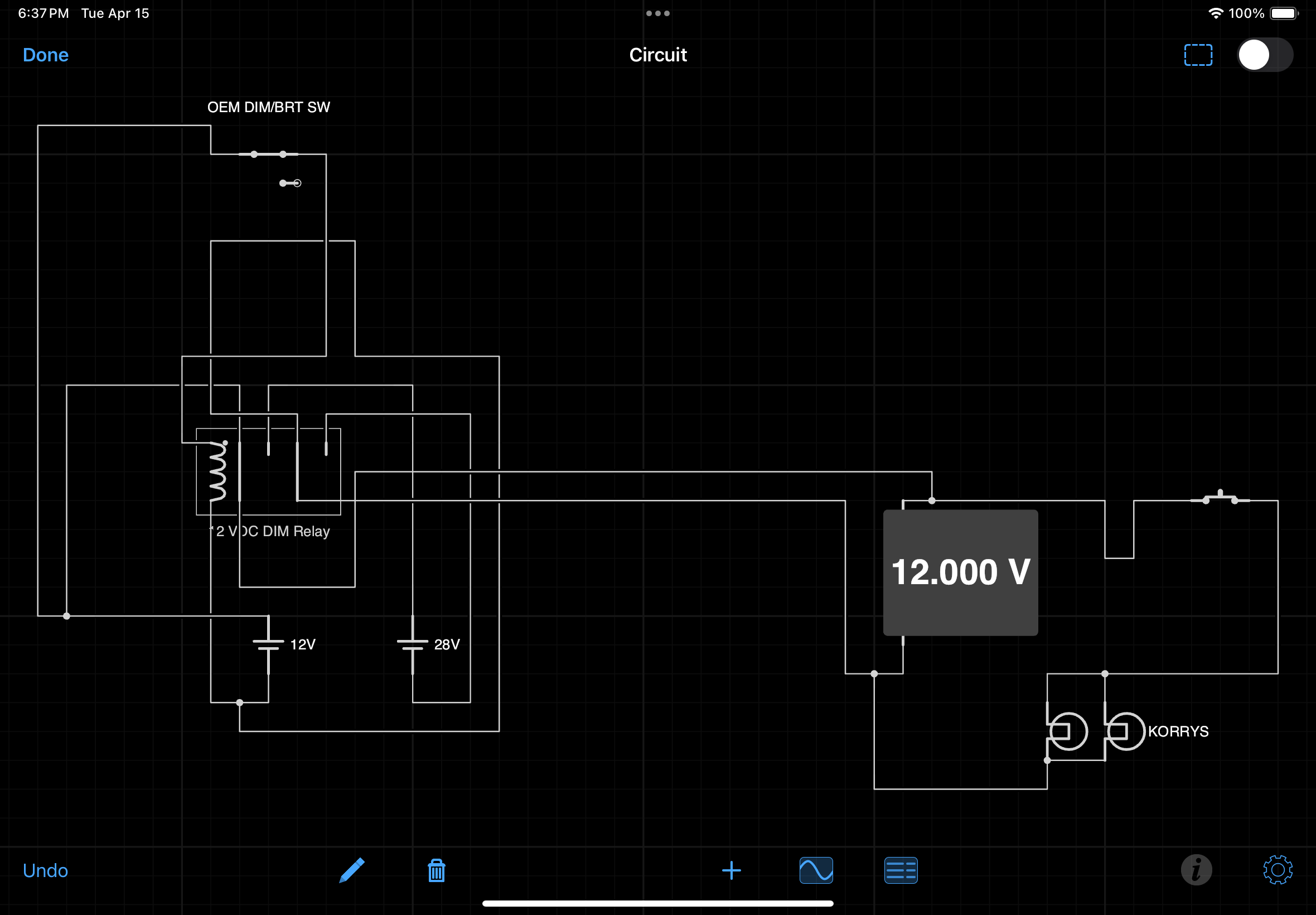
The below mud schematic may make it easier to understand.  To view the schematic at full size click the image.

Mud Schematic.  Note that grey box should say 12 Volts - not 28 Volts

A 28 volt busbar located in the center pedestal is used as a central point from which to connect various panels to (lower pale blue box).  

The busbar is connected to the terminal block located on the DIM board.  Wires from the terminal block then connect to a 16.5 and 28 volt power supply located in the PSR (orange boxes). 

The relay is also wired directly to the terminal block on the DIM board and a single wire connects the relay with the Lights Test switch located in the MIP (green box). 

From the Lights Test switch, a single wire connects with the lights test busbar located in the center pedestal (pale blue box in diagram).  The purple box represents any panel that is Lights Test compliant - a single wire connects between a panel and the lights test busbar.

Although this appears very convoluted, the principle is comparatively simplistic.

How it Works

When the Lights Test switch is toggled to the DIM position the relay is closed.  This inhibits 28 volts from entering the circuit, but allowing 16.5 volts to reach the 28 volt busbar (located in the center pedestal); any annunciators connected to this busbar will now only receive 16.5 volts and the annunciators will glow at their lowest brightness level.  Conversely, when the switch is toggled  to BRT or to Lights Test, the relay opens and the busbar once again receives 28 volts.

Which Annunciators are Connected to DIM Functionality

The annunciators that connect with the DIM board are those in the fire suppression panel, various panels in the center pedestal (that use 28 volt korrys), the forward and aft overhead, and in the MIP.  If further annunciators in other systems require dimming, then it is a matter of connecting the appropriate wires from the annunciator to the 28 volt busbar, and to the lights test busbar, both of which are located in the center pedestal.

  • The nomenclature for the 12 Volt relay is: 12 V DC coil non-latching relay part number 92S7D22D-12 (Schneider Electric).

BELOW:  A rather poorly produced video showing the two brightness levels.  The example shows the annunciators in the OEM Fire Suppression Panel (FSP).  The clicking sound in the background is the Lights Test switch being toggled from BRT to DIM and back again.  Note that the colour of the annunciator does not alter - only the brightness.  The colour change in the video, as the lights alter intensity, is caused by a colour temperature shift which is not visible to the naked eye but is recorded by the video.


Diagram showing passage of electricity through the circuit as the BRT/DIM toggle is selected (allow to video to play lead in)


A rather poorly produced video showing the two brightness levels.  The example shows the annunciators in the OEM Fire Suppression Panel (FSP).  The clicking sound in the background is the Lights Test switch being toggled from BRT to DIM and back again.  Note that the colour of the annunciator does not alter - only the intensity (brightness).  The colour change in the video, as the lights alter intensity, is caused by a colour temperature shift which is not visible to the naked eye but is recorded by the video.


Glossary

  • Annunciator - A light that illuminates under set conditions.  Often called a Korry.

  • Busbar - A bar that enables power to distributed to several items from a centralised point.

  • Mud Schematic - Australian colloquialism meaning a very simplistic diagram (often used in geological mapping / mud map).

  • Push-To-Test Function - All annunciators have the ability to be pushed inwards to test the circuit and to check if the globe/LED is operational.

  • OEM - Original Equipment Manufacturer aka real aircraft part.

  • Panel/Module - Used interchangeably and meaning an avionics panel that incorporates annunciators.

  • Toggled- A verb in English meaning to toggle, change or switch from one effect, feature, or state to another by using a toggle or switch.

  • UPDATED: 17 April 2025, 05 May 2025

Flight Testing The SimWorld MCP and EFIS

SimWorld MCP retrofitted into a Flight Deck Solutions (FDS) MIP.  Initial impressions exceed expectations, especially when comparing the appearance of the MCP to the OEM item

I have been using the Mode Control Panel (MCP) and Electronic Flight Instrument System (EFIS) produced by CP Flight.  These units have been the mainstay in the flight simulation community for several years and for the most part they are robust, reliable, and more or less look similar to the OEM units. 

Recently, other companies have begun to manufacture MCP and EFIS units to replicate the real aircraft part as closely as possible in both appearance and functionality. 

SimWorld, located in Poland is a relatively new company that is making great leaps forward designing and manufacturing reproduction 737 Next Generation panels and other components.  One of SimWorld's premier items is their 'plug and play' MCP and EFIS.

I am currently in possession of a SimWorld MCP and two EFIS units.  These units have been retrofitted into a Flight Deck Solutions (FDS) MIP and flight testing has begun.  In due course a detailed review will be published.  I also will be, at the same time, reviewing the CANBUS system that SimWorld use to connect their various panels to the computer and Flight Simulator.

To test and evaluate the unit will take some time as the protocols I use are very thorough.  In the next few months (depending upon time) I should have enough data to enable a detailed review to be written.  The review will address at the minimum the following:

  • Manufacturing technique (materials, painting, laser cutting, etc);

  • Accuracy and scale to the OEM MCP/EFIS

  • Robustness and longevity;

  • Functionality to OEM unit;

  • Quality assurance;

  • SimWorld pre-sales and after-sales support;

  • Reliability and consistency in operation; and,

  • An overview of the CANBUS system.

Note that I have no affiliation with SimWorld, or any other manufacturer.  This review will be a balanced opinion based on my use and the use and opinion of other users of the MCP and EFIS unit.

Glossary

  • EFIS - Electronic Flight Instrument System.

  • MCP - Mode Control Panel.

  • MIP - Main Instrument Panel.

  • OEM - Original Equipment Manufacturer (aka real aircraft parts).

Update

UPDATE 07-03-2017 by FLAPS 2 APPROACH: There have been a few problems that needed to be sorted out on the MCP that was sent to me for evaluation.  After considerable testing by myself and SimWorld, it was determined the problem stemmed from a number of unreliable potentiometers.  These potentiometers were part of a bad batch delivered by the supplier.  Filip at SimWorld decided the best option was to manufacture a new MCP and this has only just been received via UPS.

Interestingly, the replacement MCP has a number of improvements over the old-style model which includes the use of Swiss-made commercial-grade potentiometers.

Over the next few weeks I will flight test the new-style MCP and document the results in a separate post.

Update

on 2017-04-07 07:02 by FLAPS 2 APPROACH

UPDATE 07-04-2017 by FLAPS 2 APPROACH: Finally, after considerable flight testing and editing a review which was very long, the final review of the SimWorld MCP and EFIS has been published.   I hope it answers the questions that many have been asking me in private messages and e-mails.

And to answer the question to whether I am impressed with the panels and will be keeping them in my simulator - Yes I will be - unless an OEM Collins panel appears at a reasonable price :)

Replacement Curtains - B737 OEM Throttle Dust Curtains

OEM dust covers for the Boeing throttle. there are slight colour variation depending upon manufacturer

Interesting items can arrive in the post.  Earlier today I opened a small parcel to find a collection of grey coloured pieces of material.  To anyone else they would appear exactly as they do – pieces of material stamped with numbers.

The throttle quadrant I use is original equipment manufacture (OEM) and once plied the skies above Europe.  As such it is a used item with the usual wear and tear you expect from a well-used aircraft part. 

One item that continually caught my attention was the dust curtains or skirts that sit behind the two thrust levers.  In my throttle, the curtains had been abused at some point and were torn and the edges looked rather ragged in appearance.  Although a replacement curtain could have been made by using vinyl or another similar material it would not be the same. 

The numbered pieces of material now have a home – they are OEM dust curtains that will replace the damaged curtains on the throttle.

Installing the Dust Curtains

The B737 throttle quadrant has three dust curtains.  Two on the outer side of the thrust levers and one double-sided curtain that resides between the thrust levers.  Each curtain comprises three parts sandwiched together and held by three screws. 

The parts are:

(i)     The thin aluminium arc which is the outer face plate;

(ii)    The actual curtain; and,

(iii)   The plastic arc retainer. 

Dust curtains have been removed and the plastic retainer and aluminium arc can be seen along with one of the three attachment screws

The plastic arc retainer is curve-shaped and sits flush against the bare metal of the quadrant.  The dust curtain then lies above the retainer and beneath the outer face plate.

Replacing the curtains is straightforward. Remove the three screws that hold the metal arc in place to the throttle, then gentle pry loose the aluminium strip beneath which are the dust curtain and plastic arc retainer.  It’s wise to ensure that you place the parts anatomically on the workbench as each of the items must be reassembled the same way it was removed.

One aspect of Boeing philosophy which makes building a flight simulator much easier is their reuse of parts from earlier airframes.  Boeing do not always redesign a part from scratch, but add to or change existing parts.  This philosophy can save the company millions of dollars.

For those who study this type of thing, you will know that dust curtains can come in differing colour shades.  In general, the older classic style throttle used a paler grey/cream coloured skirt whilst the Next Generation airframes use a standard light grey colour.  But, I would not get too concerned if the colour does not exactly match.

Why are the Dust Curtains Important

The main purpose of the dust curtains is to minimise the chance of foreign bodies falling into the throttle mechanism.  Think pens, rubbers, straws, paper clips and coke can pull tabs (or anything else pilots play with in the flight deck).  The dust curtains are made from a fire retardant material (not asbestos) which minimises the chance of any fire/sparks from licking up the sides of the thrust levers in the unlikely event that a fire develops inside the throttle quadrant.

For those keen to find replacement OEM dust curtains the stock numbers are: 69-33918-8 REF, 69-33918-9 REF-F and 69-33918-10 REF-F.

Glossary

  • Anatomically – Meaning items removed are placed on a table in the same position as they were when they were in place.

  • Curtain Arc – the semi circular arc that the dust curtains are attached to.

  • OEM – Original Equipment Manufacture (aka real aircraft part).

  • Plastic Arc Retainer – A piece of heavy duty plastic shaped as a curve (arc).

Protection for Interface Cards - USB Isolator

Phidget 3060 USB Isolator mounted on acrylic base

In the first of two previous posts we discussed surge protectors and the need for a protector to secure your simulator system from unwanted power surges.  The second post addressed circuit breakers in more detail and examined the different types of breakers that can be used.  In this final post I will discuss the use of an isolator to protect both your computer and any USB connected interface cards.

Multiple Phidget Card Failure

Recently I had to replace several Phidget interface cards.  The cards failed following failure of the internal power supply on my server computer.  The reason for the power supply failure is unknown, however for whatever reason a surge traveled through the USB port to the SMART module irreparably damaging two Phidget 0/16/16 cards and two Phidget 1066 motor controllers.

I contacted Phidgets in Canada who were very helpful in diagnosing the reason for the card failure.  Apparently it is not unheard of for powered Phidget cards to cease working following the failure of a computer power supply that Phidget cards are attached.

Potential Problem

The discussion with the technician highlighted a potential problem that Phidget cards are susceptible to.

When the internal computer power supply (CPS) fails the circuits are no longer fully operational which may cause unregulated power to briefly travel the shortest route to leave the system.  PCI cards and USB ports are for the most part totally unprotected and act as a first port of call for any unwanted transient power.  The power then travels through the connected USB cable to whatever is attached.  Although the surge (I will call it a surge) may only be a millisecond, it is enough to fatally damage or shorten the life of an attached interface card.  

Bear in mind that not every instance of a power supply failure will result in a surge; it depends on how the power supply failed.  In my case, when the power supply failed 5 volts continued to be distributed.  However, I believe the 5 volts was not clean power meaning that the voltage fluctuated.

The technician commented that it is relatively uncommon for the event described above to occur.  He suggested that a far more common issue is that, following the failure of a powered Phidget card, the unregulated power travels to the computer via the connected USB cable (the opposite direction to what happened in my situation).  In these circumstances, the USB port, PCI card, internal computer power supply, or worse still – the computer’s motherboard can be destroyed.

For a more detailed explanation with examples, I refer you to the Phidget website.

Phidget 3060 isolator – the size of a credit card, the isolator can provide protection for both the computer and the interface cards that are connected to it.  This isolator is installed into the SMART module and provides protection for the two 0/16/16 cards and two 1066 motor controllers

The Solution

Fortunately there is an easy solution to this potential problem: Phidgets 3060 USB isolator.  

The isolator is connected between the USB port and the interface cards.  In this way the cards are protected from the computer and the computer is protected from the cards, wiring and external power supplies used to power the cards.

The 3060 isolator installed into the Throttle Interface Module (TIM).  The isolator has been installed into an acrylic casing.  Although the casing is by no means necessary, it ensures that the isolator card does not become contaminated by dust.  The blue-coloured plastic band is temporary only

The 3060 isolator is a tad smaller than the standard-sized credit card and does not require a power supply.  The isolator has two USB connections, one side has a mini and the other side a standard connection.  This enables in-line connection of the isolator between the computer’s USB port and interface card/power hub.

In addition to the protection already mentioned, the isolator also protects against possible basic wiring errors and different ground voltages.  In some circumstances the isolator can also assist to stabilise a system form untimely USB disconnects.  The isolator achieves this by maintaining the correct voltage.

The interface cards used in the simulator have been mounted in standalone interface modules that in turn connect via USB to the server computer.  To protect the contents of each module, a 3060 isolator has been installed into each interface module.

Computer Power Supplies (CPS)

Although this problem was easily solved by purchasing replacement interface cards and installing isolators, it should not have occurred in the first place and it brings into question the reliability and quality of computer power supplies.

The choice of a CPS is often by chance, being the unit supplied with the computer (probably a inexpensive Chinese model).  However, CPS’s are not identical and you get what you pay for.  

Many manufactures claim a specific output/voltage/wattage from their power supplies, however only a few manufactures check and guarantee these outputs.  The last thing you want is a power supply that has fluctuating voltage or a unit that is rated a particular output but does not meet this requirement.  

The CPS installed in the server computer was not a quality item (it came with the computer and was not upgraded despite the remainder of the computer being re-built to flight simulator specifications).  For a few months I had noted that the CPS appeared to be running quite warm.  In hindsight, I should have realized the tell-tail symptoms of an impending problem.  

The failed CPS has been replaced with a Corsair RM750x Power Supply.  This particular model is used when tight voltage control is needed.  

Other benefits of using a Corsair CPS is that the capacitors are Japanese made and provide consistent and reliable output.  Furthermore, Corsair bench check every unit to ensure that they meet the outputs published.

Final Call

It is your call whether the expenditure and use of a USB isolator is warranted.  Certainly replacing Phidget cards can be expensive, not too mention the time required to install and rewire.  The isolator should be viewed as a type of insurance policy  - a 'just in case' option.

Further Information

The isolator is designed by Phidgets primarily to operate with powered Phidget cards.   The interface modules I use have Phidget, PoKeys and Leo Bodnar cards installed and connecting an isolator did not cause any issues with the operation of these cards.

I do not know if the isolator will cause problems with other USB standalone modules.

This post is but a primer.  For additional information, refer to the Phidgets website.  Note I am not affiliated with Phidgets in anyway.

Glossary

  • CPS – Computer Power Supply.

  • PCI Card – Computer bus for connecting various hardware devices.


UPDATE 2016-01-19 08:25 by FLAPS 2 APPROACH: I have been contacted by another flight simulator builder who has stated that he used a Phidgets isolator and had problems with Open Cockpit modules disconnecting.  He decided that then isolator caused more problems that what it was worth (USB disconnects). 

Although I cannot comment on his situation, the isolator is primarily designed to be used with Phidget cards that are powered, not non Phidget cards or un-powered cards.

Circuit Breakers For Self Preservation

Selection of Eaton Memshield MCB circuit breakers

Following on in the same theme as my earlier post Are You Protected - Power Surges, we discuss in more detail the various circuit breakers that can be used in a simulator setting.  Additionally, it is stressed that electricity can kill and a qualified electrician should be contacted prior to implementing anything suggested below.

My thanks to Dave Egkkman (flight simulator enthusiast based in the United Kingdom) who has written this article.  I think the content adds considerably to my earlier post and I am grateful to Dave for writing and allowing it to be posted here.

Circuit Breakers and Fuses 

It is a common misconception that fuses and circuit breakers are there for personnel protection. It is very important to understand that this is not the case.

It can take as little as 0.03A to kill a human being, that’s 30mA! So, if you have a circuit protected by a 30A fuse/circuit breaker, it will allow 1000 times more current to flow than it takes to kill, before it breaks the circuit and stops the current flow.

Fuses and circuit breakers (protective devices) are there to protect the cabling in an electrical circuit from damage by overload. This is achieved by installing a suitably rated circuit breaker at the beginning of a circuit. The rating of the protective device will be calculated to protect the lowest rated cable in the circuit, by stopping the flow of current in an overload situation before the current flow exceeds the current rating of the cable.

A common scenario in the UK is the use of 13A fuses in plugs. In domestic plugs in UK, the plug can take a variety of fuses rated from 1A to 13A. Often loose plugs are supplied fitted with a 13A fuse or, if a fuse ‘blows’ the user will commonly fit a 13A fuse as a replacement. However, if the appliance is a lamp standard, the cable from the plug to the electrical appliance could be rated at 6A or less.

So, in the event of a fault developing that allows 10A to flow, the fuse will not break the circuit, but the cable could well overheat and catch fire, and still the fuse may not break the circuit.

Fuses

A fuse is simply a piece of small wire designed to melt and break the circuit if more current flows than the fuse wire is designed to allow to flow.

In some cases, faults can occur in which the current may not be large enough to melt the fuse but enough to seriously harm the user of the electrical appliance. Circuit breakers generally offer better protection

Circuit Breakers

For domestic installations there are three main types of circuit-breakers:

  1. Miniature Circuit Breaker (MCB);

  2. Residual Current Circuit Breaker (RCCB) or Residual Current Device (RCD); and,

  3. Residual Circuit Breaker with overload (RCBO).

Protec 63A 363-2C-6kA Triple Pole MCB circuit breaker

Miniature Circuit Breaker (MCB)

The MCB is a protective device typically used where a fuse would have been. MCBs are quicker to respond than fuses, are more reliable, more sensitive and can be reset once the fault has been cleared, the problem identified and fixed.

There are many different configurations of MCBs, which we won’t go into here. We should however consider the three different ‘Types’ that are available. All 3 MCB types use a magnetic fault protection, which trips the MCB within one tenth of a second when the overload reaches a set level.

How a MCB Works

Basically, the live input cable is wound around an iron core. As current flows a magnetic Field is generated. If the magnetic field reaches a pre-set level, an iron latch is pulled towards the iron core (magnet) and breaks the circuit.

In normal domestic use a Type B MCB will be used. A Type B breaker will trip between 3 and 5 times full load current.

For electrical loads that have a high inrush current when they are switched on, a Type B breaker is likely to trip as it ‘sees’ the inrush current as an overload.

A Type C breaker trips between 5 and 10 times full load current. This allows the MCB to withstand the initial inrush current, whilst still providing overload protection in normal use.

A Type D breaker trips between 10 and 20 times full load current, typically used where high inductive loads are present such as motors and transformers.

For those with problems of an MCB (or a fuse) tripping when turning on equipment, a Type C breaker may be the answer. Selecting the correct Type and rating of breaker is not an arbitrary decision. An electrically qualified person should make this decision.

Whichever MCB type is used, it is extremely dangerous to cut corners by using inferior quality devices, therefore they should only be bought from a reputable supplier. Copy and cheap MCBs have been found to have no copper/nickel/silver contacts within them, just steel. Upon introducing a fault, the contacts simply weld together, the consequences are obvious. Don’t go cheap.

ETI 25A 30mA RCD 2 throw circuit breaker

Residual Current Device

A residual current device IS designed to offer personnel protection. RCDs are used in combination with fuses and MCBs.

Residual current circuit breakers work by comparing the current entering the appliance via the live input with the current leaving the appliance through the neutral.

How a RCD Works

The live wire and neutral wire within the device, are wound around iron cores in opposite directions. When the appliance is working correctly ALL the electrical current entering the appliance via the live wire, exits the appliance through the neutral wire. The magnetic fields generated around the iron cores cancel out.

In the event of a fault some of the electric current will flow through the earth wire, casing of the appliance or in the absence of proper earthing through the body of the user. This results in an imbalance between the current entering the appliance through the live wire and the current exiting through the neutral wire.

This difference in electrical current is called the residual current and it is what causes the device to break the circuit.

Residual Current Circuit Breakers have the advantage of being highly sensitive with a very quick response time.

There are various ratings of RCDs. Typically, in domestic use a 30mA RCD will be used, but 10mA is also common. Selecting the correct Type and rating of RCD is not an arbitrary decision. A qualified person should make this decision.

It is not unusual for people to complain that RCDs suffer from nuisance tripping. If an RCD is tripping there is a problem, the problem should be identified and corrected. If an upstream RCD is tripping, rather than the local RCD, for example the RCD in the house trips and the one in the out building does not, then the configuration of the circuit is incorrect. These issues should be addressed by, yes you guessed it, a suitably electrically qualified person. Issues of disconnection times, voltage drop, resistance of the earth path all need to be considered.

Residual Circuit Breaker with overload

A residual circuit breaker with overload (RCBO) protection is a device that combines overload and personnel protection.

They are often used where there is not enough space for an MCB and RCD in one consumer unit / fuse board.

Disclaimer

This information is provided to offer guidance only and hopefully to suggest when an electrically qualified person should be approached for guidance. It is not comprehensive and only scrapes the surface of the subject of electrical protection.

I don’t want to come across as ‘holier than thou’ but, I really don't wish to be drawn into offering guidance to people about which and what protective devices should be used for their particular installation. I don't even agree with DIY companies selling fuse boards, MCBs etc. I'm hoping my words will encourage folks to seek professional advice from a local engineer/electrician who can assess their own situation. It's not the same as deciding which interface card to use for TQ servo activation!

All electrical work must be carried out by a qualified engineer/electrician and this post is not suggesting otherwise.

Glossary

A - Amp

mA - Milliamp