Are You Protected - Power Surges

The power requirement, or more to the point the regulation of the power is often overlooked when building a functional flight deck. 

A basic desktop-style simulator controlled by a single computer and displayed on two computer monitors will draw very little power and can easily be connected to a single household wall socket.  However, as a simulator build becomes more complex and incorporates multi-displays and various other pieces of equipment the power requirements become more complex.  

In this post, I will discuss the basics surrounding the distribution of power, in particular amperage draw.  I will also address the need for surge protection. 

This post is an introduction into the somewhat confusing and complicating world of electricity and power quality; it is not intended to be a definitive work.

Amperage Draw

The biggest issue with many simulators is amperage draw, with many builds drawing close to, if not over 10 amps.  Drawing in excess of 10 amps can cause a standard household circuit breaker (or fuse) to be triggered cutting off the electricity supply to the simulator.

Although a power shut down from the triggering of a circuit breaker can be annoying, especially if part way through a simulator flight, a bigger problem is that many interface cards including Phidget cards may lose important configuration and calibration parameters if they are ‘murdered1by a power shutdown.

Amperage Draw, Circuit Breakers and Zones

The power distribution in a modern house is distributed into zones (circuits).  

A zone will have any number of power points attached to it, and will be protected by a dedicated circuit breaker of specific amperage.  For example, water and heat is one zone, while lighting and power points can be spread across one, two or more zones (depending on the number of lights and their respective amperage draw). 

In Australia, all standard household power points (except heat and water) are rated at 10 amps while the wire that runs from the power point to the circuit board is rated at a higher capacity; usually 15 amps.  

If the power requirements exceed 10 amps within a zone, then the circuit breaker on the circuit board will be triggered and the electricity will cease to flow into that zone.

Many will be accustomed to this inconvenience, when they have a number of heaters plugged into various power points within one zone.  Turning on the kettle to boil water, will then be enough to exceed the power amperage for that zone and the circuit breaker will be triggered.

  • My next post will take a more detailed look at circuit breakers and the types that can be used in various situations, so more more on this later.

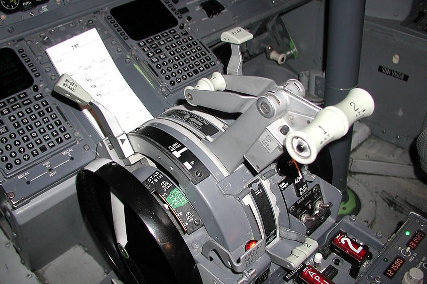
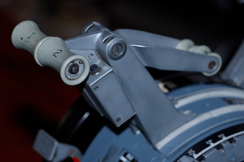
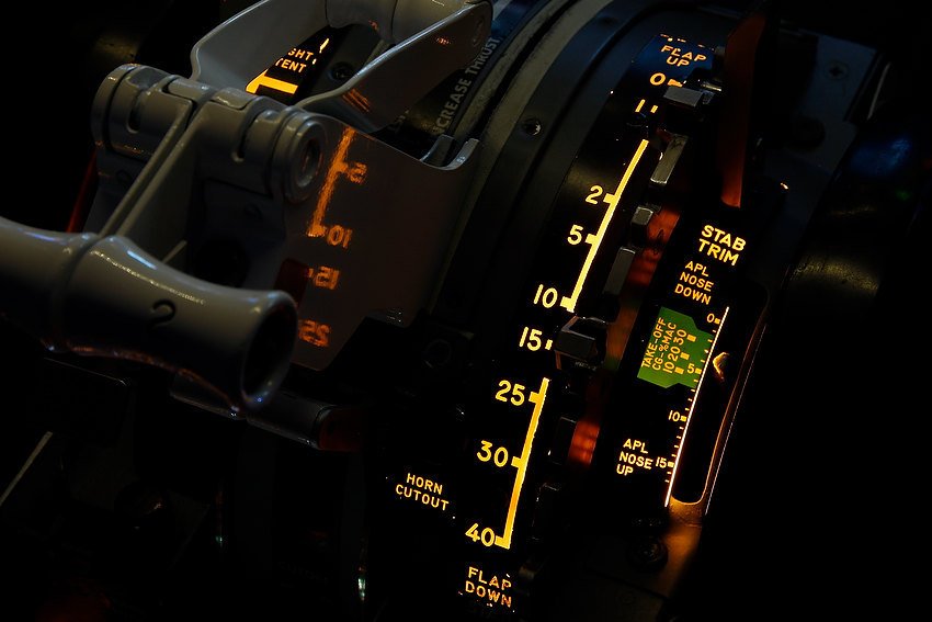
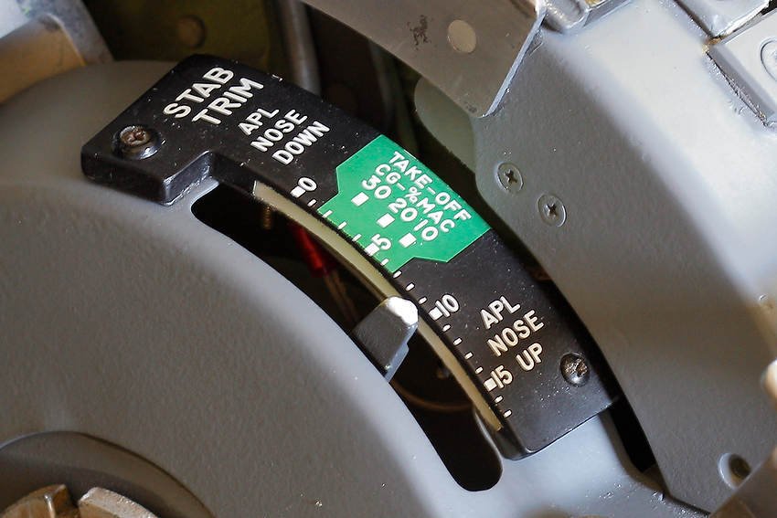
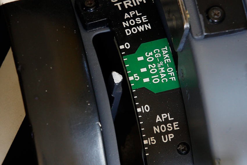
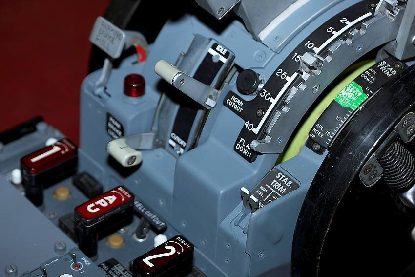
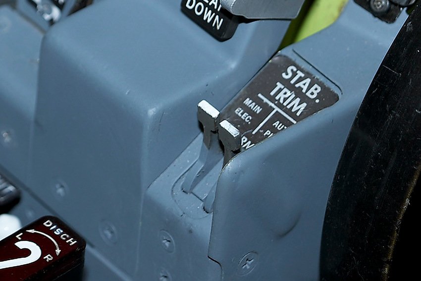
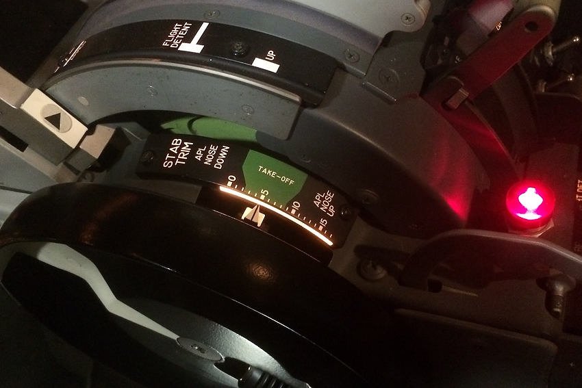
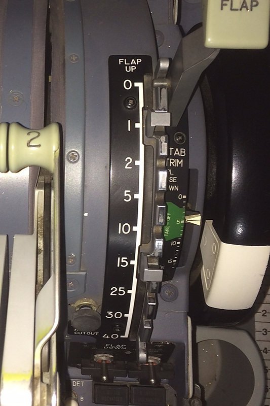
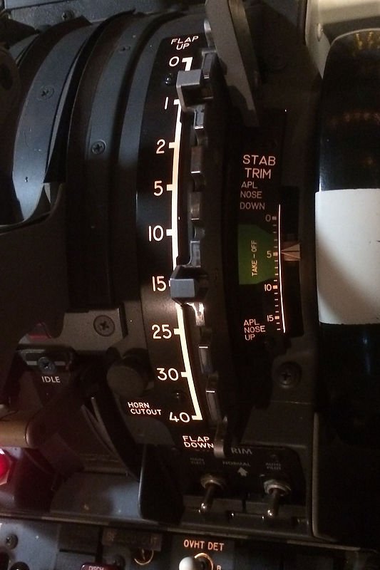
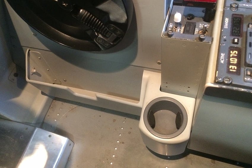
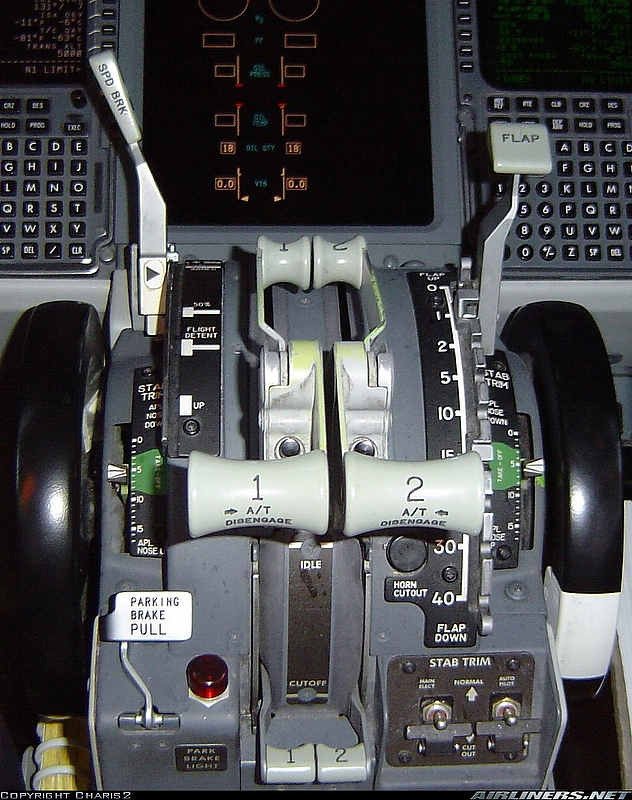
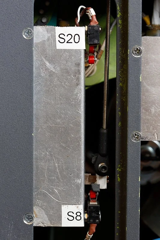
Amperage draw and status can be measured if an appropriate gauge is installed and the wiring connected correctly.  The gauges in the picture are measuring amperage status of different sectors (5 & 12 volt sectors) in the Throttle Interface Module

Amperage Draw and Heat

An easy method to enable a greater amperage draw is to replace the 10 amp circuit breaker with one rated at a higher capacity.  This will alleviate the situation of the circuit being tripped every time you exceed 10 amps.  Whilst this is feasible, after all the wire running between the board and the power point is 15 amps, it is not recommended.  

A by-product of drawing too many amps along one wire is heat, and although the wire may be rated at 15 amps, the heat may cause electrical wrapping to begin to melt.  Furthermore, if the amperage draw is maintained the power point may begin to melt and burn due to the exceeded amperage draw.

Calculating Amperage Draw

Calculating the amperage draw can be complicated as equipment can draw different amperage at different times.  For example, a computer when turned on will initially draw more amperage; however, this draw will lower after the initial start cycle has been completed.

Often, you can cause an over-amperage draw that triggers a circuit breaker by starting everything simultaneously.  To minimise this occurring, it is best to start different systems sequentially keeping the amperage draw to a minimum and below the 10 amp rating of the circuit breaker.

Upgrading the Amperage

If the simulator (or any number of electrical appliances) draws more than 10 amps, and the circuit breaker continuously is triggered, there are two methods in which to solve the problem.  

First, is to have an electrician replace the wire for the zone that the simulator is connected to.  This involves replacing the 10 amp power point with a power point rated at 15 amps, running higher capacity wire between the power point and circuit breaker, and using a higher amperage circuit breaker in the circuit board.  A 15 amp power point also incorporates a larger blade assembly (earth) on the plug..

The second method is to spread the power requirements over two or more zones.  This way, if the simulator operates across two 10 amp zones you will have 20 amps of power available.

The downside of the second method is that you will need to have power points in close proximity to each other that connect to two zones; otherwise, an extension cable may need to be run between the simulator and the designated power point.

Sine wave data read-out showing the tell-tail spike of a power surge

Power Surges, Noise and Clean Power

Unfortunately, power is not clean and everyone will experience at sometime or another voltage fluctuations (power surges).  The severity and frequency of the fluctuations will depend  upon the ability of the power grid to obtain, store and distribute power.  

The power requirements of a large industrial complex powering on in the morning maybe enough to cause a fluctuation (surge) as it draws initial power from the grid.  Furthermore, surges in power can often occur when the electrical company adjusts the grid to take into account the day and night-time power requirements of the surrounding region.  

Whilst these are standard day to day activities, a major disruption in power, with resultant surges and spikes, can occur during severe storm events.  During such events, power disruptions can be common as poles and wires are damaged due to high wind and torrential rain.  In the most extreme case, an electrical discharge from lightening can occur directly on your home or in an area nearby.  If your house is struck by lightning, then there is very high chance that permanent damage will result to any plugged in equipment.

Is this problematic – yes and no.  An odd low level minor surge will probably not cause too much grief; however, a high volume power surge or a constant surge can damage equipment.  

A high-end simulator usually incorporates numerous interface cards, system boards and other delicate components which, more often than not, are not amiable to power surges.  

A high volume or constant power surge may destroy the motherboard, power supply and USB PCI cards in the computer, in addition to destroying interface cards attached to the computer.  However, minor power surges may not enlist any observable damage (other than the lights flickering or dimming briefly), but they may shorten the effective life of attached components leading to premature burnout.

Six plug power surge protection board with internal circuit breaker manufactured by Belkin.  Two LED lights indicate on/off and earth leakage while the circular black pop out switch is a standard-type circuit breaker.  The Belkin is probably one of the more popular boards and provides average protection with a rating of around 600 Joules (depends on model)

Surge Protection and How It Works

There are several pieces of equipment that can be used to protect electronic equipment; the most common being a surge protector board.  

In essence, a surge protector board is a glorified power board with some type of mechanical mechanism that is either destroyed or partly destroyed when a power surge occurs.  Higher end protectors may also provide noise filtering and a internal circuit breaker.

The level of protection provided by a surge protector is, at its bare minimum, determined by the level of Joules the board is rated at.    Joules (J) is a derived unit of energy as defined by the International System of Units and should be thought of as a reservoir of protection.  

Simply put, a board rated with a high number of Joules has a larger reservoir and therefore provides greater protection for a longer period of time.   For example, if a board is rated at 525 Joules, the board will provide protection for either one power surge rated at 525 Joules or any number of smaller power surges below 525 Joules until the rating is exceeded.  

The design of the board is such that once the level of protection (Joules) has been exceeded, the board will need to be replaced.  

Many minor power surges go completely unnoticed, and although you did not notice the surge, the surge protector will have filtered the power imbalance and lost a portion of its own protection (Joule reservoir).  This can lead to a false sense of security as many protector boards will still function, albeit without any form of available protection.  Inexpensive surge protectors often do not have any type of indicator to warn when their Joule reservoir is about to, or has been exceeded.

Re-set Buttons

Many surge protector and extension boards have a reset button.  The reset button has nothing to do with surge protection or resetting the board after a power surge has occurred.  Rather, the button is the reset for the circuit breaker which is for protection against a short circuit or over-load condition that could otherwise cause the wiring to melt with the board.

Main Types Of Power Surge

The following is an excerpt from Electrosafe, a company based in New Zealand.

Dropout

This is where a portion of the sine wave has a lower than expected value or is missing entirely, usually for a portion of a cycle. These types of problems can be caused when large motors are started, spot welders are operated, during lightning strikes, or when electrical equipment fails. Dropouts can lead to failures in computers and electronic equipment, reduced the life of motors and causing lights to flicker.

Power Failure

When the duration of a dropout exceeds 1 cycle it is usually referred to as a power failure, or blackout. This problem is usually the easiest to recognise.

Sag or Brownout

A power sag (or low line voltage) is a decrease in line voltage of at least 10% of the average line voltage for half a cycle or longer. The power sag is often caused by large inductive equipment, e.g. photocopy, bank of fluorescent lights.  Sags can be caused by external factors as well, such as large power draining equipment used in other buildings.

Sags can be particularly detrimental to electronic equipment because of the malfunctions caused by the sudden decrease of available voltage to the power supply. Relays and solenoids can chatter generating spikes. Complete failure rarely occurs, however equipment lockup or lockout can occur requiring a resetting process.

Often equipment continues to operate, with the user, unaware of any problems that may have occurred.

Surge

A power surge is the opposite of a sag and is often referred to as ‘High Line Voltage’.   A surge is defined as an increase in line voltage above 253 volts (on a 230V Line) for a half cycle or longer. Like the sag, the power surge is often caused by large inductive loads being applied on the same line. Power surges can cause some of the most dangerous situations, and their resulting damage is most difficult to repair.

Direct Relationship

There is a direct relationship between the amount of protection provided, the cost for that level of protection, and the price it is to replace the items destroyed.  Furthermore, there is a convenience factor.  How easy is it to replace and rewire the damaged component verses the cost of protection.

A generic extension board featuring back lit on/off button and a red LED, that when illuminated, instills confidence in the words 'surge protected'.  This particular board does not have any form of surge protection and is not protected by a internal circuit breaker

Almost 'Spiritual' Protection

Some manufacturers of surge protectors often claim almost ‘spiritual’ protection; however, not every board is identical in the level of protection offered.

Inexpensive surge boards may only work once, and then not provide any indication to whether they have been damaged.  Recall that many surges are invisible and only the surge protector will know a surge has occurred.  

Other protectors do not provide high level protection, meaning that your equipment will be protected by a minor power surge, but not by a higher or continuous surge.

Many inexpensive power extension boards sport on their faceplate the writing ‘surge protected’.  These boards are nothing more than glorified power boards and are not suitable for the protection of delicate equipment against any form a power surge.

Circuit Breakers Verses Surge Protection

A circuit breaker will provide an initial level of protection against a power surge – provided the circuit breaker trips, does not malfunction, and the intensity of the power surge is great enough to trigger the circuit breaker.  However, a circuit breaker is NOT designed to filter electrical noise or minor power surges – these electrical imbalances will not trigger a circuit breaker and the electricity will travel to the power point and onward to any equipment attached to the power point.  As discussed earlier, minor power surges are responsible for shortening the life of many components.

It should be remembered that although a circuit breaker will probably be triggered during a high volume or continuous power surge, the breaker may not trigger if the power surge is minimal.  It also worth remembering that a circuit breaker does not trip immediately a power surge enteres its circuit.  There is a millisecond or two delay.  This delay can be enough for power to travel through the circuit breaker to any delicate equipment attched to a power point.

A circuit breaker is designed to trigger when there is an over amperage above the circuit breaker's rating.  it protects the wires from over-amperage and overheating and potential for fire to occur.  A surge protector - which may also incorporate a circuit breaker,  is designed to protect/filter against power surges.  Although both pieces of equipment are similar, there end uses are different.

I have used, for several years, surge protectors manufactured by Belkin.  In general they were reliable and each unit provided two LED lights to warn if the device was not working.  However, Belkin protectors have a limited life time based on their Joule reservoir, which in moderately priced units is around 525 Joules.

Novaris PP10A/4 surge filter.  Simple LEDs indicate functionality of the unit while a push to reset circuit breaker button is located on the side of the unit.  4 power points facilitate connection of plugs or extension boards

Novaris Tasmania

Considering the expense and the amount of time that has been expended into building the simulator, I decided to up the ante and purchase a more solid and reliable system to protect against possible unwanted power surges, noise and spikes.  

Novaris Tasmania sounds more in-line with something Stephen Hawkens has recently discovered and named in a far away galaxy; however, the name belongs to a Tasmanian company that develops and manufacturers surge protection equipment explicitly for industries that operate delicate equipment.

Two PP10A(4) surge filters manufactured by Novaris in Tasmania, Australia were commissioned.   For those more technically or theoretically inclined, read the PP10A/4 specification sheet.

The simulator, with everything operational, draws very close to 10 amps; therefore, to stop the possibility of the household circuit breaker tripping if the 10 amp boundary is crossed, various simulator sectors are connected to two power points in two power zones.  At each power point I have installed a PP10A/4.  

The PP10A/4 enables four extension boards to be attached, which between two units, is more than enough to ensure that everything in the simulator is protected.

Complete Protection - Modems and Routers

Often forgotten is the need to also protect against unwanted noise and surges that may be transmitted along copper wires from the telephone line to the router, modem and switch box (assuming the simulator is connected to the Internet).

This may or not be an issue depending upon the type of wiring that has been used – older style copper wires have good conductivity; therefore, these wires will transmit the effects of a power surge; however, modern glass wire has minimal conductivity which lessons the opportunity for electricity to migrate.

Many surge protectors also provide protection in this area; however, as stated earlier the effectiveness of any surge protector to protect against unwanted power surges is dictated by its Joule reservoir.

Final Call

This post has focused, in the simplest terms, on the concept of household power distribution and the need for some type of surge protector.  In a future post, I will discuss other methods of protecting delicate components from unwanted surges in power – in particular how to protect interface cards from damage from internal power spikes caused by computer power supply failures, reverse spiking, and grounding issues.

1 Murdering is a term used in the computer industry to describe when a process is stopped suddenly (such as turning the power off) without allowing the correct closing procedure to be followed.

Major Differences Between Classic and Next Generation Throttle Quadrants

There is little mistaking the tell-tale white-coloured handles and skirts of the Next Generation Throttle

The advent of high quality reproduction parts that marry with advanced avionics suites, such as ProSim-AR and Sim Avionics, has led many flight simulator enthusiasts to strive closer to Microsoft’s claim ‘as real as it gets’.

The availability of OEM parts formally used in classic airframes has never been greater, and many enthusiasts are purchasing various parts and converting them to flight simulator use.

The ‘holy grail’ of conversion has always been the Boeing throttle unit, and depending upon individual requirements, many older style throttle units have been retrofitted to appear very similar, if not near-identical, to their Next Generation counterparts.

This article will compare and contrast the major differences between the Boeing 737 classic throttle and the Next Generation throttle.  The word classic is usually used to refer to airframes belonging to the 200, 300, 400 and 500 series.  The Next Generation (NG) refers to the Boeing 600, 700, 800 and 900 series.

Boeing 727-100 throttle quadrant.  Although there are obvious differences in that the 727 has three engines, the overall design and appearance of the quadrant is very similar to its modern counterpart.  Image copyright to Keven Walchle

Historical Context

The throttle quadrant observed in a modern airliner has relatively old roots. 

The fore bearer of the Next Generation throttle was designed in the late 50's and early 60's and was initially used in the Boeing 707 airframe.  As aircraft types evolved, throttle design remained relatively static with similar-designed throttles being used in the Boeing 727, 717 and 737 series aircraft.

The B737-100 made its debut in April 1968, to be followed shortly by the 200 series with a slightly longer fuselage.  During the 1980’s Boeing released the classic series of airframes (300 through to 500 series). 

During this time, the technology altered little and the design of the throttle quadrant reflected the ability of Boeing to reuse existing technology with minimal alterations.  This principle of reuse can save a company millions of dollars in redesign and development costs.

This Goes With That (Compare and Contrast)

The Boeing 737-800 Next Generation is the airframe that many enthusiasts strive to duplicate in a flight simulator.  The reason for this two-fold.  First, the Next Generation is the most umbilicus aircraft flown today, and second, the availability of software that mimics the avionics suite in this aircraft.

However, Next Generation parts are difficult to find, and when found are expensive to procure.  Fortunately for the simulation community, a throttle will function correctly in flight simulator no matter what airframe the throttle originated.

Many of the nuances between a classic and Next Generation throttle quadrant are subtle, and for the most part only the more knowledgeable will notice.  

The more obvious highlights of the Next Generation are the white-coloured thrust lever shrouds, TOGA button assembly, détentes flaps arc, speedbrake lever knob, and the moulded white-coloured side panels and panniers of the lower part of the throttle unit.  Whilst it's possible to alter many of the attributes of a classic throttle to conform with those of an Next Generation, not every part can be easily transformed.  For example, the flaps détentes arc between the classic and Next Generation is very different in design and appearance, and cannot be altered.

TABLE 1: Overview to the main visual differences between the classic and Next Generation throttle quadrants (courtesy Karl Penrose who kindly allowed the use of photographs taken of his 600 series throttle).  Note that there may be other subtle differences, some visual and others in design/operation. 

The table doesn't address the center pedestal as pedestals vary greatly between airframes. 

Retrofit refers to the level of difficulty it is to make the classic throttle appear similar to the Next Generation. Yes meaning it is possible and no, for the most part, meaning it is not possible.


TABLE 1: an overview to the main visual differences between the classic and Next Generation throttle quadrants


1Erratum:  The trim wheels on the Next Generation are slightly smaller in circumference to those of the Classic series.

2  The words 'level of difficulty' is subjective; it depends on numerous factors such as experience and knowledge – neither of which is identical between individuals.

Important Point:

  • By far the most challenging hurdle during a Next Generation refit is the the alteration of the throttle lever shrouds and the TOGA button assembly.

Final Call

The differences between a classic and Next Generation throttles are largely cosmetic with some subtle design and operational differences.  Retrofitting a classic throttle to appear similar to a Next Generation throttle is possible.  However, there will be some things that probably won't be altered, such as the speedbrake lever handle, stab trim indicator tabs, side mouldings, panniers and flap détentes arc.  

This said, the ability to use an OEM throttle, no matter from which airframe, far supersedes any reproduction unit on the market.  OEM throttles are sturdy, robust and well-built.  Unless you do something particularly foolish, you won't damage an OEM throttle.

BELOW:  Two image galleries showing the various differences between the classic and Next Generation throttle quadrants.  Thanks to Karl Penrose who kindly allowed the use of photographs taken of his 600 series throttle.  To stop the slideshow, click the image and navigate by the numbered squares beneath the image.

Boeing 737 Classic Series Throttle Quadrant


Boeing 737 Next Generation Series Throttle Quadrant


  • Updated 21 June 2020.

Control Wheel Steering (CWS) Explained

Collins 737 Mode Control Panel (MCP) showing location of CWS buttons on Collins MCP.  The CMD and CWS buttons are located on the First Officer side of the MCP.  Each of the four press to engage buttons has a green annunciator which illuminates when the mode is engage

CWS is an acronym for Control Wheel Steering.  Broadly speaking, it is a sub-set of the autopilot system which can used on either System A or B.  When engaged, CWS maneuvers the aircraft in response to control pressures applied to the control wheel or column.

The control pressure is similar to that required for manual flight. When control pressure is released, the autopilot holds the existing attitude until CWS is disengaged, or the autopilot is engaged. 

The Flight Crew Training Manual (FCTM) states:

‘Control Wheel Steering (CWS) may be used to reduce pilot workload. Follow the manually flown procedure but instead of disengaging the autopilot, engage CWS.’

CWS is a similar system to the ‘Fly By Wire’ system utilised by Airbus.

Advantages of CWS

The control pressures on the flight controls are in the order of 37 pounds push/pull value +- 3 pounds and continually applying this pressure for a protracted period of time can be tiring.  As such, an obvious advantage of using CWS is that you do not have to continually apply positive pressure to the flight controls to maintain a set pitch or roll attitude. 

CWS enables you to fly the aircraft using the flight controls rather than turning the heading knob on the Mode Control Panel (MCP) or configuring other modes such as Level Change, Vertical Speed, VNAV, etc.  Being able to ‘feel’ the control surfaces through the yoke and column has obvious benefits that flying using the MCP cannot convey.

CWS is also advantageous when flying in turbulent conditions (additional information below) as it results in smoother transitions than when the autopilot is used.  Furthermore, CWS also allows for greater control of the aircraft when performing touch and goes and circuits at lower altitudes.

CWS engaged during climb following flaps retraction.  The FMA displays CWS R & CWS P, the vertical speed is 2650 and pitch mode is V/S after changing from TOGA thrust following climb out

Practical Example

CWS is often used during the climb to altitude with the autopilot being engaged at 10,000 feet.  

In the example (left) the aircraft has CWS engaged during climb following flaps retraction.  The FMA displays CWS R & CWS P, the vertical speed is 2650 and pitch mode is V/S after changing from TOGA thrust following climb out.  Pitch and roll follows the FD bars and speed is 240 KIAS with altitude set to flight level 20900.  If CWS remains engaged, the aircraft will continue at this attitude. 

Airspeed is not protected when using CWS. 

Following rotation, the Flight Director (FD) bars will be followed maintaining V2+15/20 until Acceleration Height (AH) is reached.  At AH, the MCP speed will be increased to climb speed, or to a speed as required by Air Traffic Control.  As airspeed increases the flaps will be retracted.  When the flaps are retracted, the control column will be placed in a position that correlates to the Flight Director bars and CWS A or B will be engaged – the attitude of the aircraft will now be fixed.  

The aircraft, in TOGA thrust, will maintain the established pitch as it ascends to the altitude set on the MCP.  TOGA thrust is speed protected; therefore, as long as the FD bars are followed there will not be a speed incursion.  If a roll mode is selected, the navigational data provided by this mode is also promulgated to the Flight Director.  Once the desired altitude has been reached, LNAV / VNAV can be engaged.

Whether a flight crew used CWS is personal preference.  Some flight crews use it regularly while others have never used it.

Turbulence (autopilot or CWS)

The Flight Crew Training Manual (FCTM) states:

‘That during times of turbulence the A/P system (CMD A/B) should be disengaged.’

When the aircraft is flying through turbulence, the autopilot is attempting to maintain an attitude (pitch) that is based upon a predefined barometric pocket of air that is present at the altitude you are flying at.   In severe turbulence this pocket of air may not be stable and the autopilot will try to change altitude to match the changing barometric pressure.  At its worse, the autopilot may unexpectedly disconnect.

CWS provides a stable buffer in which the aircraft will maintain its position when flying through turbulence.  When CWS is engaged, it will maintain a preset attitude rather than the A/P attempting to match the attitude to changing barometric pressure.

Flight Crew Training Manuals differ in their content; each manual has been written with a particular airline.  Many virtual flyers duplicate the procedures followed by Ryanair.  This is because the documentation for Ryanair is relatively easy to find, and the policy of this airline is reasonably conservative.  As such, I have transcribed from the Ryanair FCTM the segment on the use of CWS during turbulence.

The Ryanair FCTM states:

‘Flight through severe turbulence should be avoided, if possible.  When flying at 30,000 feet or higher, it is not advisable to avoid a turbulent area by climbing over it unless it is obvious that it can be over flown.  For turbulence of the same intensity, greater buffet margins are achieved by flying the recommended speeds at reduced altitudes.  Selection of the autopilot Control Wheel Steering (CWS) is recommended for operation in severe turbulence’.

The recommended Ryanair procedures for flight in severe turbulence is:

  • Do not use Altitude Hold (ALT HLD) mode.

  • Target the airspeed to approximately 280 KIAS or 0.76 MACH, whichever is lower.

  • During severe turbulence there often will be large and often rapid variations in indicated airspeed.  Do not chase the airspeed.

  • Engage the Yaw Damper.

  • If the autopilot is engaged, use CWS position, do not use ALT HLD mode.

  • Disengage the Autothrottle (stops the autothrottle from hunting a desired airspeed)

  • Maintain wings level and the desired pitch attitude. Use the attitude indicator as the primary instrument. In extreme down and updraft conditions extreme attitude changes may occur.  Therefore, do not use sudden and excessive control inputs.  After establishing the trim setting for penetration speed, do not change the stabilizer trim.

Autothrottle Use

When CSW is engaged, the autothrottle should not be engaged.  The reason for this is because the autothrottle is coupled to the automation, and if there is a change in the aircraft's attitude there will be a corresponding change in engine thrust.

This said, I have spoken with several pilots who claim that they leave the autothrottle on when using CWS.  In some respects it depends on the severity of the turbulence encountered. 

Lazy Flying

Although not sanctioned by Boeing, some pilots use CWS as a 'lazy way' of flying, whereby they may establish the aircraft at a specific attitude and vertical speed with the autothrottle engaged.  As CWS is a sub-set of the autopilot system, trim control will still be controlled by the system and the aircraft will maintain the desired attitude until CWS is cancelled.

A Virgin First Officer has stated that, after takeoff and flaps retraction, she will often use engage CWS to climb to a specific altitude, then she will engage LNAV, VNAV and the autopilot. 

It's important to realise there are many ways, (although not sanctioned by Boeing or a specific airline policy) to fly the Boeing 737 aircraft.

Important Point:

  • There is no speed protection when CWS is engaged, except when the aircraft is in TOGA mode.

Technical Data (general)

The Flight Crew Training Manual states:

‘After autopilot engagement, the airplane may be manoeuvred using the control wheel steering (CWS) pitch mode, roll mode, or both using the control wheel and column. Manual inputs by the pilot using CWS are the same as those required for manual flight. Climbs and descents may be made using CWS pitch while the roll mode is in HDG SEL, LNAV or VOR/LOC. Autopilot system feel control is designed to simulate control input resistance similar to manual flight.'

The Mode Control Panel (MCP) has two CWS buttons located on the First Officer side of the MCP beneath the two CMD buttons (CMD A/B).  Like the autopilot, CWS has a redundancy system (system A or system B).  By default the CWS system is off (annunciator is not illuminated). 

The CWS system has been designed so it can be used with or without the autopilot.

To engage the CWS system, either of the two CWS buttons must be pressed.  When engaged, the CWS annunciator will illuminate green and the Flight Mode Annunciator (FMA) on the Primary Flight Display (PFD) will annunciate CWS P and/or CWS R.

CWS cannot be engaged when any of the following conditions are met:

  • Below 400 feet.

  • Below 150 feet RA with the landing gear in the down position.

  • After VOR capture with TAS 250 kt or less.

  • After LOC capture in the APP mode.

Important Points:

  • CWS can only be engaged when there is no pressure on the flight controls. 

  • CWS can be engaged with the autopilot engaged or not engaged.

Operation - What CWS Does

As mentioned, the CWS system can be used with or without the autopilot being engaged. 

CWS can be engaged two ways.  Either by moving the control column when the autopilot is engaged, or by pressing the CWS button on the MCP.

To use CWS in its own right, the autopilot must be disengaged.  This can be done manually by pressing the CMD button or by pressing CWS; the later will disconnect the autopilot (the CMD annunciation will extinguish and the CWS annunciation will illuminate).   To access the CWS system partially, and still use the autopilot, the control column is moved (pitch/roll) while the autopilot is engaged.

Although the CWS concept is easy to understand, documenting exactly what it does is difficult and this can cause confusion.  I wouldn't become too concerned with the 'technical jargon' below, as CWS is easy to master by using the function and remembering what it does:

The following information has been edited from documentation acquired from Smart Cockpit Airline Training.

1:  CWS selected - PITCH and ROLL   (autopilot not engaged)

  • Depressing the CWS button on the MCP engages the autopilot pitch and roll axes in the CWS mode.  It also displays CWS-P and CWS-R on the FMA on both the Captain and First Officer Primary Flight Displays (PFD).  (Note that CMD is not selected and the CMD annunciation is extinguished on the MCP).

  • With CWS engaged, the autopilot maneuvers the aircraft in response to control pressures applied to the control wheel or column.  The control pressure is similar to that required for manual flight.  When control pressure is released, the autopilot holds existing attitude and roll.

•    If the column pressure is released with a bank angle 6 degrees or less, the autopilot rolls the wings level and holds existing heading. This feature is inhibited when any of the following conditions are met:

(i)     Below 150 ft RA with the landing gear down;

(ii)    After F/D VOR capture with TAS 250 kt or less; and,

(iii)   After F/D LOC capture in the APP mode.

2:  Moving control column - PITCH  (autopilot engaged)

  • The FMA will display CWS-P.

The pitch axis engages in CWS while the roll axis is in CMD when:

(i)     The autopilot pitch has been manually overridden with control column force and the  force required for override is greater than normal CWS control column force.  Note that manual pitch override is inhibited in the APP mode with both autopilots are engaged (autoland).

Important Points:

  • When approaching a selected altitude in CWS-P with the A/P in CMD, CWS-P changes to ALT ACQ and, when at the selected altitude, ALT HOLD engages.

  • If pitch is manually overridden while in ALT HOLD at the selected altitude, ALT HOLD changes to CWS-R If control force is released within 250 ft of the selected altitude, CWS-P changes to ALT ACQ and the autopilot returns to the selected altitude and ALT HOLD engages.  If the elevator force is held until more than 250 ft from the selected altitude, pitch remains in CWS PITCH.

3:  Moving control column - ROLL  (autopilot engaged)

•    The FMA will display CWS-R.

The roll axis engages in CWS while the pitch axis is in CMD when:

(i)     The pitch has been manually overridden with control column force and the force required for override is greater than normal CWS control column force.  

Important Point:

  • With CWS-R selected and the autopilot engaged, the aircraft will capture a selected radio course while the VOR/LOC or APP mode is armed. Upon intercepting the radial or localizer, the F/D and autopilot annunciation changes from CWS-R to VOR/LOC engaged and the autopilot tracks the selected course.

Using CWS (with the autopilot engaged) - Simplified

This segment has been added in response to some readers who stated they had difficulty in understanding some of the above content.  I hope it explains, in easier terms, how the CWS system can be used when the autopilot is engaged.

Moving the flight controls (pitch/roll) during automated flight will cause the CWS system to engage.  However, the autopilot (CMD) will remain selected and the CMD annunciator will remain illuminated on the MCP. 

Flying the aircraft in this manner can be useful when hand flying an approach, but wishing to follow the automated inputs from the ILS and/or FMC.

During such a procedure the following will be noted:

Moving flight controls left or right (roll):

(i)      The autopilot annunciation will remain illuminated;

(ii)     The FMA on the PFD will alter from CMD to CWS-R;

(iii)    The AFDS will illuminate A/P P/RST; and,

(iv)    The heading annunciation on the MCP will extinguish, as will the LNAV annunciation if engaged.

The aircraft can now be flown using control wheel steering.  To return to fully automated flight, press the heading button on the MCP.  LNAV, if used, will also need selecting.

Moving flight controls up or down (pitch):

(i)      The autopilot (CMD A/B) annunciation will remain illuminated;

(ii)     The FMA on the PFD will alter from CMD to CWS-P;

(iii)    The AFDS will illuminate A/P P/RST; and,

(iv)    The heading annunciation on the MCP will extinguish, as will LNAV annunciation if engaged.

Important Point:

  • If the pitch is altered to cause the aircraft to ascend, the altitude window in the MCP must be changed to the new altitude prior to moving the flight controls (altitude capture is automatic).  This is not required if the pitch is changed to cause the aircraft to descend.

Final Call

The use of CWS is very much underused and under-appreciated - whether used as a stand-alone system, or in conjunction with the autopilot.

Although surface control loading in a simulator rarely matches that of a real aircraft, the use of CWS in a simulator environment can still have positive benefits equating to better aircraft handling, especially when flying circuits and flying in turbulence.

  • NOTE:   This article has been rewritten to aid in clarity (28 November 2021).

B737 NG Display Unit Bezels By Fly Engravity

The bezels that have replaced the acrylic bezels made by FDS. The landing gear, clock annunciators (korrys) and brake pressure gauge are OEM parts converted for flight simulator use - First Officer side. Note OEM Korrys and clock

I recently upgraded the display unit bezels (frames) on the Main Instrument Panel (MIP).  

The previous bezels, manufactured by Flight Deck Solutions (FDS), lacked the detail I was wanting.  Increasingly, I found myself being fixated by glaringly incorrect hallmarks that did not conform to the original equipment manufacturer (OEM) – in particular, the use of incorrectly positioned attachment screws, the lack of a well-defined hinge mechanism, and the use of acrylic rather than aluminum.

Although it is not necessary to have replicated items that conform to a real part, it does add to the immersion level, especially if you are using predominately OEM parts.  The MIP in my case is a skeleton on which to hang the various real aircraft parts that have been converted for flight simulator use. 

This is not a review, but more a reason to why sometimes there is a need to change from one product to another.

The OEM display is a solid unit that incorporates the avionics, display and bezel in the one unit.  This unit has the protective plastic attached to the screen

OEM Display Units

The OEM display units used in the Boeing Next Generation airframes comprise a large rectangular box that houses the necessary avionics and glass screen for the display.   

The display unit is mounted by sliding the box into the MIP along two purpose-built sliding rails.  The unit is then locked into the MIP by closing the hinge lever and tightening the thumb screw on the lower right hand side of the bezel.  The hinge mechanism is unique to the OEM unit in that once the thumb screw is loosened; one side of the lower display adjacent to the hinge becomes a lever in which to pull the unit free of its locking points in the MIP.

The units are usually manufactured by Honeywell.

The display unit is one piece which incorporates the bezel as part of the assembly; therefore, it is not possible to obtain just the bezel – this is why a reproduction is necessary.

Reproduction Bezels

Reproduction bezels are manufactured by several companies – Open Cockpits, SimWorld, Fly Engravity and Flight Deck Solutions to name a few.  As with all replica parts, each company makes their products to differing levels of accuracy, detail and quality.

I looked at several companies and the closest to the  OEM item appeared to be the bezels manufactured by Fly Engravity and CP Flight (CP Flight are a reseller of Fly Gravity products).  

The main reasons for changing-out the FDS bezels were as follows:

  • FDS bezels have two Philips head screws in the upper left and right hand side of the bezel.  These are used to attach the bezel to the MIP.  The real bezel does not have these screws.

  • FDS bezels are made from acrylic.  The bezels in the real B737, although part of a larger unit, are made from aluminum.  Fly Engravity make their bezels from aluminum which are professionally painted with the correct Boeing grey.  

  • FDS have not replicated the hinge in the lower section of the bezel.  Rather, they have lightly engraved into the acrylic a facsimile of the hinge .   Fly Engravity fabricate a hinge mechanism, and although it does not function (there is absolutely no need for it to function) it replicates the appearance of the real hinge.

  • FDS use 1mm thick clear Perspex whereby the real aircraft uses smoke grey-tinted glass.  Fly Engravity bezels use 3 mm smoke grey-tinted Perspex.

  • The Perspex used by FDS is very thin and is attached to the inside of the bezel by double-side tape.  The thinness of the material means that when cleaning the display it is quite easy to push the material inwards which in turn breaks the sticky seal between the Perspex and the inside of the bezel.  Fly Engravity use thicker Perspex that is attached to the inside of the bezel by four screws.  It is very solid and will not come loose.

Table 1 provides a quick reference to the assailant points.

Detail showing the hinge mechanism in the Fly Engravity bezel.  Although the hinge is non-functional, the detail and depth of the cut in the aluminium frame provides the illusion of a functioning hinge mechanism

Attaching the Bezels to the FDS MIP

The FDS and Fly Engravity bezels are identical in size; therefore, there is not an issue with the alignment of the bezels with MIP – they fit perfectly.

Attaching the Fly Engravity bezels to the FDS MIP is not difficult.  The Fly Engravity bezels are secured to the MIP using the same holes in the MIP that were used to secure the FDS bezels. However, the screws used by Fly Engravity are a larger diameter; therefore, you will have to enlarge the holes in the MIP.  

Detail of the hinge thumb knob on the Fly Engravity bezel.  Although the internal screw is missing from the knob, the cross-hatched pattern on the knob compensates.  The knob is screwed directly into the aluminium frame and can be loosened or tightened as desired.  The circular device is a facsimile of the ambient light sensor (

For the most part the holes align correctly, although with my set-up I had to drill two new holes in the MIP.

The Fly Engravity bezels, unlike the FDS bezels, are secured from the rear of the bezel via the backside of the MIP.  The bezel and Perspex have precut and threaded holes for easy installation of the thumb screws.

Cross section of the Fly Engravity bezel showing the detail of the Perspex and attachment screw

Upgrade Benefits - Advantages and Disadvantages

It depends – if you are wishing to replicate the real B737 MIP as much as possible, then the benefits of upgrading to a Fly Engravity bezel are obvious.  However, the downside is that the aluminum bezels, in comparison to acrylic-made bezels are not inexpensive.

The smoke grey-tinted Perspex has definite advantages in that the computer monitor screens that simulate the PFD, ND and EICAS appear a lot sharper and easier to see.  But a disadvantage is that the computer monitors colour calibration alters a tad when using the tinted Perplex.  This is easily rectified by calibrating your monitors to the correct colour gamut.  I was concerned about glare and reflections, however, there is no more using the tinted Perspex than there is using the clear Perspex.

The Fly Engravity bezels have one minor inaccuracy in that the small screw located in the middle of the hinge thumb knob is not simulated.  This is a small oversight, which can be remedied by having a screw fitted to the knob.

Improvements

A possible improvement to the Fly Engravity bezels could be to use flat-headed screws, or to design a recessed head area into the rear of the Perspex (see above photograph which shows the height of the screw-head).  A recessed area would allow the screw head to sit flush enabling the monitor screen to be flush with the rear of the Perspex. 

The inability of the monitor screen to sit flush with the Perspex does not present a problem, but it is good engineering for items to fit correctly.

Final Call

Although the bezels made by FDS do not replicate the OEM item, they are still of good quality and are functional.  However, if you are seeking authenticity and prefer an aluminum bezel then those produced by Fly Engravity are superior.

Endorsement and Transparency

I have not been paid by Fly Engravity or any other reseller to write this post.  The review is not endorsed and I paid full price for the products discussed.

Glossary

  • EICAS – Engine Indicator Crew Alert system.

  • MIP – Main Instrument Panel.

  • ND – Navigation Display.

  • OEM – Original Equipment Manufacturer (aka real aircraft part).

  • Perspex - Poly(methyl methacrylate), also known as acrylic or acrylic glass as well as by the trade names Plexiglas, Acrylite, Lucite, and Perspex among several others.

  • PFD – Primary Flight Display. 

New Interface Module Installed - SMART

737-800 OEM flaps gauge. A new interface module was designed to incorporate the 400 hertz needed to power the gauge

The installation of an OEM flaps gauge to the simulator was the catalyst to the design and development of an additional interface module. 

The module, called SMART is a platform to primarily accommodate the various components necessary to configure and drive the flaps gauge.

SMART has also been used to accommodate the interface cards needed to operate the following;

The SMART module has been discussed in a separate section as a subset to the Interface Module section.

10 Mile ARC to VOR 30 Approach - Hobart, Tasmania Australia (YMHB)

Approach chart depicting VOR 30 Approach to YMHB.  Important points to note are: initial approach courses to intercept the arc (295 & 334), the D10 HB arc, the altitude increments of 4000, 3000 and at 7 miles, 2400, and the Initial Approach Fix (IAF) and speed of 210 kias

Recently, I flew from Brisbane to Hobart and the pilot flying made a different style of approach to what normally is made at this airport.  After landing, I approached the pilots and queried the approach.  The Captain stated that he had decided to fly a semi-automated VOR approach along an arc to land at runway 30. 

The reason being, that Air Traffic Control (ATC) had warned them of turbulent conditions near the airport.  He commented that in such conditions, he felt more confident using the older style arc approach using LNAV/VNAV with Speed Intervention (SPD INTV) engaged, with a transition to Vertical Speed and VOR once on final.

The First Officer stated that this was the first time he had seen an arc being used to set-up for a VOR approach.  He said that usually they use ILS into RWY 12 or RNAV into RWY 30.  He commented that the only time he had made a VOR approach was during simulator training, and then he would probably only use such an approach, if the ILS was inoperative or there was an issue with RNAV.

The use of this approach is a prime example of the variation offered to pilots in relation to how they fly and land the Boeing 737. 

Screen Images

Several screen captures from the Instructor Station, CDU and Navigation Display (ND) which I hope will make it easier to understand this post.  The avionics suite used is ProSim737 distributed by ProSim-AR.  Note that some of the mages are not sequential as I captured the images over two simulator sessions.

How To Set-Up An Arc

To set-up an approach using an arc is very easy.  

The following example is for Hobart, Tasmania Australia (YMHB).  The instructions assume that you are conversant with operating the CDU and have a basic understanding of its use.  

Essentially, an arc is using a Place/Bearing/Waypoint to define an arc around a point at a set distance.  The distance between each of the generated waypoints along the arc, is at the discretion of the flight crew.

Approach Charts

To determine the correct distance to create the arc, the approach chart for the airport should be consulted.  The chart, in addition to providing this information, will also aid you in decided where to place the final waypoint (if wanted) along the approach course.

In this example, the YMHB VOR 30 approach states that the aircraft must fly an arc 10 miles from the airport between an altitude of 4000 and 3000 feet before descending to be at 2400 feet 7 miles from the runway  threshold.

The approach chart depicted is provided by Lufthansa Systems (LIDO/FMS) distributed by Navigraph

CDU Instructions

(i)    Open the FIX page and type in the scratchpad the airport code (YMHB).  After uploading, type the distance (/10 miles).  This will create a green-dotted citcle around YMHB with a radius of 10 miles.

(ii)    Open the LEGS page and type into the scratchpad the airport code (YMHB).  Immediately following YMHB, type the required radial1 (in degrees) from the airport that you wish the initial waypoint to be generated.  Follow this with a slash and type in the distance from the airport (YMHB340/10).  

This will generate a waypoint 10 miles from YMHB on the 340 radial.  This is the waypoint from which you will begin to build your arc.  

Obviously, the radial you use to define the location of your first waypoint will depend upon the bearing that you are flying toward the airport.

(iii)    To Generate the ARC you must repeat the above process (ii) changing the radial by 10 degrees (or whatever you believe is needed) to generate the required waypoints around the arc at 10 miles from the airport.  As an example: YMHB320/10, YMHB340/10, YMHB000/10 and so forth until the arc is built.

As you upload each of the radials you will note that the name for the waypoint is changed to a sequential number specific to each waypoint.  As an example; the above waypoints will each be named YMH01, YMH02 and YMH03.

If you make a mistake, you can delete a waypoint and start again; however, realize that the sequential numbers will not be in order.  This is not an issue (it is only a number) but it is something be aware of.

In our example, the VOR approach is for runway 30.  Therefore; your final waypoint on the arc will be YMHB121/10.  Prior to reaching this waypoint, if flying manually, begin the right hand turn to intercept the approach on the 121 radial (bearing 300 degrees).

A Note About /-+

The more observant will note that the distances in the example above do not utilise the /+ key before the distance (YMHB340/+10).  When entering the distance it can be with or without the + key.  

Variation

Before going further, there are many ways to fly the B737.  The method selected is at the discretion of the pilot in command and is dependent upon airline preferences, environmental conditions, and pilot experience.  This statement was stressed to me when I spoke with the Captain of the aircraft.

Often an approach will incorporate a number of automated systems including VNAV, LNAV, Vertical Speed, Level Change, VOR Localizer and old fashioned manual VFR flying.  In most cases the particular approach will be programmed into the CDU, at the very least for situational awareness.  However, the CDU does not have to be used and often a step down approach is a good way to maintain flying skills and airmanship.

Handy Hints

The following hints will assist with situational awareness and in allowing the aircraft to be guided by the autopilot to a point to which manual flight can commence.

If you carefully study the approach chart for YMHB VOR 30, you will note that the altitude the aircraft should be at when at 7 miles from the threshold should be 2000 feet.  The chart also depicts the letter D at this point meaning that a continuous descent can be made this point.

Hint One - visual descent point (VDP)

To make the transition from the arc to the approach easier, create a waypoint at the 7 mile point from the airport along the radial used for the approach (YMHB121/7).  Using a waypoint allows the aircraft’s Lateral Navigation (LNAV) to be used.  This type of waypoint is usually referred to as a Visual Descent Point (VDP).

When the waypoint at 7 miles from the threshold is reached, a transition to manual flying can commence, or Vertical Speed can be used to maintain a 3 degree glidepath (GP) while following the VOR.  Remember to change the EFIS from MAP to VOR so you can use the VOR indicator during the approach.

Hint Two - extend runway line

Assuming you have not inserted an approach into the CDU, an aid to increase situational awareness is to select the correct runway from the CDU and enter a distance that the runway line is to be extended from the threshold.

To do this, select runway 30 from the ARRIVALS (ARR) page in the CDU (RWY30) and type the numeral 7 (or whatever distance you require) into the scratchpad and upload.  This will extend the green line from the runway threshold to the previously generated waypoint at 7 miles.  Ensure you clean up any discontinuity (if observed) in the LEGS page.

This enables three things:

  1. The generation of a 3 degree glidepath (GP) from the distance entered (example is 7 miles) to the runway threshold.

  2. It enables LNAV (even if the autopilot is not engaged) to continue to provide the Flight Director (FD) with heading information during the approach, and 

  3. It enables the Navigation Performance Scales (NPL) on the Pilots Flight Display (PFD) to provide glidepath (GP) guidance (assuming that the correct runway or approach is selected in the CDU and NPL is enabled within the ProSim737 avionics suite).

UPPER LEFT: Screen capture from the instructor station PFD and ND for the approach into YMHB.  The aircraft, after turning right from the 10 mile arc, is aligned with the 121 radial approaching the waypoint YMH07 (the WP entered at the 7 mile point).  LNAV is engaged and the aircraft is being controlled by the autopilot.  As RWY 30 was inserted into the route, the Navigation Performance Scales (NPS) show Glidepath (GP) data in the Primary Flight Display (PFD).  Note that the EFIS is still on MAP and is yet to be turned to VOR.  In real life, VOR would have been selected earlier (click to enlarge).

LOWER LEFT:  The transition from LNAV to VOR has occurred and the autopilot and autothrottle are not controlling the aircraft. The aircraft is on short final with gear down, flaps 30 and the airspeed is slowly decaying to VREF+5. 

The EFIS has been changed from MAP to VOR to allow manual tracking using the VOR needle. The NPS show good vertical alignment with a lateral left offset; the VOR indicator confirms this.  The Flight Mode Annunciator (FMA) displays LNAV (although the autopilot is disengaged) and the Flight Director (FD) and NPS show glidepath (GP) data.  The Flight Path Vector (FPV) symbol shows a continuous descent at roughly 3 degrees.  The altitude window and heading on the MCP has been set to the appropriate missed approach (4200/300).  Click image to enlarge.

Do Not Alter Constraints

As alluded earlier, there are many ways to accomplish the same task.  However, DO NOT alter any constraints indicated in the CDU if an approach is selected and executed.  CDU generated approaches have been standardised for a reason.

Finding the Correct Radial/Bearing to Build Your Arc

Finding the correct bearing to use on the arc can be challenging for those less mathematically inclined.  An easy method is to use one of the two MCP course selector knobs.  

Rotate the knob until the green dotted line on he Navigation Display (ND) lies over the area of the arc that you wish the waypoint to be created.  Consult the MCP course selector window - this is the figure you place in the CDU.  Next, rotate the knob a set number of degrees and repeat the process.  You can also consult the data displayed along the course indicator line on the Navigation Display (ND). 

When you build the arc, ensure you have set the EFIS to PLN (plan).  PLN provides more real estate to visualize the approach on the Navigation Display (ND).  You can use STEP in the LEGS page to cycle through the waypoints to ensure you have an appropriate view of the surrounding area.

Important Points

  • Always double check the Place/Bearing/Waypoint entries in the CDU and in the ND (PLN) before executing.  It is amazing how easy discrepancies can occur.

  • Always check the approach plate for the approach type you are intending to make.  Once again, mistakes are easy to make.

  • If using VNAV, double check all speed and altitude constraints to ensure compliance with the approach chart and situation (some airlines promote the use of the speed intervention button (SPD INTV) to ensure that appropriate speeds are maintained).

  • If need be, select the approach (ARR) in the CDU to provide added situational awareness.

Images

The following are screen captures from the instructor station CDU and Navigation Display (ND).  Ignore altitude and speed constraints as these were not set-up for the example. Click each images to enlarge.

LEFT: Circular FIX ring has been generated around YMHB at 10 mile point.  The arc waypoints will be constructed along this line.

LEFT:  Various waypoints have been generated along the 10 mile fix line creating an arc.  The arc ends at the intersection with the 212 radial for the VOR 30 approach into YMHB.  The route is in plan (PLN) view and is yet to be executed.

LEFT:  The constructed arc as seen in MAP view.  From this view it is easy to establish that the aircraft is approaching TTR and once reaching the 10 mile limit  defined by the 10 mile FIX (green-coloured dotted circle), the aircraft will turn to the left to follow the arc waypoints until it intersects with the 121 radial.

LEFT:  This image depicts the waypoint generated at 7 mile from the threshold (YMHB121/7).  This waypoint marks the point at which the aircraft should be on the 121 radial to VOR 30 and at 2400 feet altitude (according to the VOR 30 approach plate.

LEFT:  RWY 30 has been selected from the arrivals (ARR) page.  This displays the guidepath (GP) assistance. it also generates a runway line extending from the threshold to 7 miles out; the same distance out from the threshold that the final waypoint was generated.

The course line is coloured pink indicating that LNAV is enabled and the aircraft is following the programmed route. 

At the final waypoint (YM10) the autopilot (if used) will be disengaged and the aircraft will be flown manually to the runways using the VOR approach instrumentation and visual flight rules (VFR).  The EFIS will be changed from MAP to VOR.  LNAV will remain engaged on the MCP to ensure that the NPL indications are shown on the PFD.  The NDL indicators provide glidepath (GP) guidance that is otherwise lacking on a VOR approach.

Final Call

I rarely use automated systems during landing, unless environmental conditions otherwise dictate.  I prefer to hand fly the aircraft where possible during the approach phase, and often disengage the autopilot at 5000 feet.  If flying a STAR and when VNAV/LNAV is used, I always disengage the autopilot no later than 1500 feet.  This enables a safe envelope in which to transition from automated flight to manual flight.

Using an arc to fly a VOR approach is enjoyable, with the added advantage that it provides a good refresher for using the Place/Bearing/Waypoint functionality of the CDU.

Additional articles that address similar subjects are:

Glossary

  • CDU – Control Display Unit (aka Flight Management Computer (FMC).

  • EFIS – Electronic Flight Instrument System.

  • LNAV – Lateral navigation.

  • RADIAL/BEARING – A radial radiates FROM a point such as a VOR, whilst a bearing is the bearing in degrees TO a point.  The bearing is the direction that the nose of the aircraft is pointing.

  • VNAV – Vertical Navigation.

Below G/S P-Inhibit Annunciator (korry)

OEM Captain-side G/S P-Inhibit korry illuminated during daylight operations.  All OEM korrys can easily be seen during the day, as they are powered by 28 volts that power two incandescent bulbs.  This korry came from a 737-500

The Below Glideslope (G/S) P-Inhibit annunciator (korry) is located on the Main Instrument Panel (MIP).  There are two identical korrys; one on the Captain and the other on the First Officer side.

All korrys have a push to test functionality and the G/S P-Inhibit korry is no different in this regard; however, what makes this korry different is its additional ability to inhibit an aural warning and extinguish an annunciator, when the light plate is depressed.  This is what the P of P-Inhibit stands for (P=push).

The korry 318 indicator operates by a dry set of momentary contacts, which are controlled by pressing the annunciator light plate.  The part number for this korry is 318-630-1012-002.

Below G/S P-Inhibit Annunciator - Function

The Below G/S P-Inhibit korry is a radio altitude alert and is displayed (annunciates) when there is deviation in the glideslope during an ILS approach.  If the aircraft deviates more than 1.3 dots below the glideslope, the korry will illuminate amber, followed shortly thereafter by an aural warning ‘glideslope’.

This alerts the flight crew to a deviation in glideslope and a possible fly into terrain situation.  The volume and repetition rate of the aural and visual warning will increase as the deviation from glide slope increases.

However, at times the aural warning is not necessary; therefore, a flight crew can silence the aural warning by pressing the korry.  This will cancel or inhibit the alert if the aircraft is at or below 1000 feet Radio Altitude, but is above 50 feet Radio Altitude (RA).

Warning Lights - GPWS and MCS

The korry is part of the Ground Proximity Warning System (GPWS) which provides for several ground proximity alerts for potentially hazardous flight conditions (modes) involving imminent impact with the ground.  The G/S P-Inhibit korry is addressed in MODE 5 of the GPWS modes.

The GPWS loosely falls within the Master Caution System (MCS) in which various coloured warning lights and aural warnings are generated to reflect certain conditions.  The key to the condition colours are as follows:

  • Red lights – Warning:  Indicate a critical condition that requires immediate action.

  • Amber lights – Caution:  Require a timely corrective action.

  • Blue Lights – Advisory:  Do not require any action by flight crew.

  • Green lights – OK: Indicate a satisfactory or on condition.

The Below G/S P-Inhibit korry is amber coloured; therefore, the caution condition generates a priority of 18 (according to the MCS).

Triggering

The Below G/S P-Inhibit korry is armed / triggered when the following conditions are met:

  • Armed when number 1 glideslope receiver has a valid signal and the aircraft is less than 1000 feet RA.

  • Excessive deviation below the glideslope.

  • Excessive deviation (1.3 dots) below of an ILS Glideslope between 1000 feet and 150 feet.

Simulation and Configuration

The 318 korry is an OEM aircraft part and must be connected to an interface card that supports 28 volts to enable illumination of the korry.  I have used a Phidget 0/16/16 interface card. 

There are four aspects that need to be addressed when configuring this korry to operate in the flight simulator.

  • The initial connection of the OEM annunciator to a interface card and power supply;

  • The illumination of the annunciator (amber warning);

  • The playing of the aural call-out (glideslope); and,

  • The cancellation (inhibit) of the illumination and the aural call-out.

Whether the korry operates as intended in the simulator depends primarily upon the avionics suite used.  Certainly, ProSim-AR (using User-Offsets) and Sim Avioincs (using FSUIPC offsets) can be configured to allow the korry to illuminate.  The the push to test and push to inhibit function can also be configured.

However, there is a high probability that only the illumination will work if a reproduction annunciator is used.  The reason being, that stock standard annunciators do not replicate the push to test and push to inhibit functions.

Glideslope Audio File

The glideslope aural call-out is part of the default sound suite that comes with ProSim737.  To ensure you hear the call-out, open the ProSim737 audio program and scroll through the list of available sounds.  Ensure you have the glideslope sound ticked (checked).  The volume of the call-out can be adjusted in the same place.

ProSim-AR Configuration

The following instructions should provide enough information for you to configure the 318 korry in ProSim-AR.  Configuration is done within the config menu of the ProSim737 main module (switches, indicators and audio).  The Phidgets library is accessed to determine digital outputs.

  • config/configuration/combined config/mip/switch/Glideslope (push to inhibit pushed) - Register the output of the korry in ProSim by pressing the annunciator.  This will display the output number.  Either record the number by clicking the A letter, or manually input the Phidget card information and digital output number (*).  Remember to do this for both the Captain and First Officer annunciators.

  • open Phidgets library - Select the correct Phidget card from the displayed list and open the digital outputs.  Find the digital output that corresponds to the glideslope annunciator (work your way through the list of outputs clicking each digital output to you discover the correct entry).  When found, click the Turn On command in the call-out box.  If you have selected the correct digital output, the glideslope annunciator should now illuminate.  Remember the digital output (**).

  • config/configuration/combined config/mip/indicator/Below GS CP & Below GS F/O - From the menu call-out box select the correct Phidget card number (you may have to scroll down) and select the correct output number (from earlier step marked**).

  • config/configuration/combined config/audio/glideslope - From the menu call-out box select the correct Phidget card number and then select the correct output number (from earlier step marked **).

OEM 737 Next Generation Captain-side korry

Classic and NG Differences

The function of the korry used in the classic and NG series airframes is identical.  However, there are differences in appearance.  The classic has a yellow bulb colour when illuminated and the lens displays G/S INHIBIT on two lines.  The NG korry has a more orange coloured hue, and displays BELOW G/S P/INHIBIT on two lines.

Further Information

To read more about OEM annunciators, how to wire them, and the main differences between OEM and reproduction units:

  • Last Update:  October 25, 2021.

Throttle Quadrant Rebuild - New Wiring Design and Rewiring of Center Pedestal

oem 737-500 center pedestal. the panels change as oem components are purchased and converted

Put bluntly, the wiring in the center pedestal was not to a satisfactory standard.  Several panels were daisy chained together, the wires were not colour coded, and the pedestal looked like a rat’s nest of wires.  Likewise, the wiring of the Master Caution System (MCS) required upgrading as several of the original wires showed signs of fraying.  

A word of thanks goes to a friend (you know who you are...) who helped wade through the labyrinth of wires!

This post shares several links to other pages in the website.

Wiring Redesign (pedestal and panels)

The set-out of the inside of the center pedestal was redesigned from the ground up, and several of the pedestal panels re-wired to ensure conformity to the new design standard, which was neater and more logical than its predecessor.  Additionally, the MCS was rewired using colour-coded wire and the wires labeled accordingly.

New Design (panels must be stand-alone)

The new design called for each panel (module) that was installed into the pedestal to be stand-alone.  Stand-alone means that if removal of a panel was necessary, it would be a simple process of unscrewing the DZUS fasteners, lifting the panel out and disconnecting a D-Sub plug and/or 5 volt backlighting wire.   Doing this with panels that were daisy chained together was impossible.

The following panels have been re-wired:

(i)      EVAC panel;

(ii)     Phone panel;

(iii)   ACP units (2);

(iv)    On/off lighting/flood panel; and,

v)      Radar panel.

737-800 EVAC panel, although not a panel that resides in the pedestal, it demonstrates the 'stand-alone' panel philosophy.  One D-Sub plug with labelled and colour-coded wire.  The mate of the D-sub resides inside the pedestal with the wires connected to the appropriate busbar

All the panels have been retrofitted with colour-coded and labeled D-Sub connections.  Removing a panel is a simple as unfastening a DZUS connector, disconnecting a D-Sub connector, and unscrewing the 5 volt backlighting wire from the 5 volt terminal block (if ued).  If a USB cable is needed for the panel, then this must also be disconnected.

A word concerning the ACP units, which were converted some time ago with an interface card located on a separate board outside of the unit.  As part of the rebuild, the two ACP units were completely re-wired to include the interface card within the unit.  Similar to the fire suppression panel, the ACP units are now stand-alone, and only have one USB cable which is used to connect to the computer.  The First Officer side ACP is daisy chained to the Captain-side unit.

Center Pedestal Flat Board

A flat board 1 cm in thickness and constructed from wood was cut to the same dimensions of the pedestal base.  The board was then attached to the inside bottom of the pedestal by screws.  The wood floor has been installed only to the rear two thirds of the pedestal, leaving the forward third open to allow easy access to the platform floor and area beneath the floor structure..

Attached to the flat board are the following items:

(i)       FDS 5 Volt IBL-DIST panel power card (backlighting for FDS panels);

(ii)      28 Volt busbar;

(iii)     5 Volt busbar (backlighting);

(iv)     12 Volt relay (controls backlighting on/off tp panel knob);

(v)      Terminal block (lights test only);

(vi)     Light Test busbar;

(vii)    OEM aircraft relay; and a,

(viii)    Powered USB hub (NAV, M-COM, ACP & Fire Suppression Panel connection).

The 5, 12 and 28 volt busbars (mounted on the flat board) receive power continuously from the power supplies, mounted in the Power Supply Rack (PSR) via the System Interface Module (SIM). Each panel then connects directly to the respective busbar depending upon its voltage requirement.  

In general, 5 volts is used for panel backlighting while 12 and 28 volts is used to power the fire suppression panel, EVAC, throttle unit, phone panel and other OEM components

The flat board has a fair amount of real-estate available; as such, expanding the system is not an issue if additional items need to be mounted to the board.

Lights Test busbar.  Similar in design to the 5 volt busbar, its use centralizes all wires and reduces  the number of connections to a power supply.  Despite the pedestal rewire, there is still a lot of loose wire that cannot be 'cleaned up'.  The grey coloured object is the flat board

Lighting Panel Knob (backlighting on/off)

All the panels in the center pedestal require 5 volt power to illuminate the backlighting.  The general purpose knob located on the pedestal OEM lights panel is used to turn the backlighting on and off.  

Instead of connecting each panel’s wire to the on/off lights panel knob – a process that would consume additional wire and look untidy, each wire has been connected to a 10 terminal 5 volt busbar.  The busbar in turn is connected to a 12 volt relay which is connected directly with the on/off knob.

When panel lights knob is turned from off to on, the relay closes the circuit and the busbar is energised; any panel connected to the busbar will automatically receive power.

The busbar and relay are mounted to the flat board.

This system has the advantage that it minimizes the number of wires that are connected to the lights panel knob.  It also enables one single high capacity wire to connect from the relay to the knob rather than several smaller gauge wires.  This minimises the heat produced from using several thinner wires.  It is also easier to solder one wire to the rear of the panel knob than it is to solder several wires.

Lights Test and DIM Functionality

The center pedestal also accommodates the necessary components (Lights Test busbar) to be able to engage the Lights Test and DIM functionality.  These functions are triggered by the Lights Test Toggle located on the Main Instrument Panel (MIP).  

All wires have been corrected colour coded to various outputs and wire ends use ferrules to connect to the card

Interface Cards

In the previous throttle quadrant, a number of interface cards were mounted within the center pedestal. 

To ensure conformity, all the interface cards have been removed from the pedestal and are now mounted within one of the interface modules located forward of the simulator. 

Furthermore, all the wiring is colour-coded and the wire ends that connect into the I/O cards use ferrules.

The First Officer-side MCS completely rewired.  The MCS has quite a bit of wiring, and making the wire neat and tidy, in addition to being relatively accessible, was a challenge

The use of ferrules improves the longevity of the wiring, makes wire removal easier, and looks neater.

Wiring and Lumens

Needless to say, the alterations have necessitated rewiring on a major scale.  Approximately 80% of the internal wiring has had to be replaced and/or re-routed to a position that is more conducive to the new design.

The majority of the wiring required by the throttle unit now resides in a lumen which navigates from the various interface modules (located forword of the simulator) to the Throttle Communication Module (TCM).  

From the TCM the lumen routes through the throttle firewall, along the Captain-side of the throttle unit before making its way to the flat board in the center pedestal.  

The exception to the above is the cabling required for a powered USB hub located within the center pedestal, the wires required for the Lights Test (from the Lights Test Toggle located in the MIP), and the various power wires navigating to the pedestal from the Power Supply Rack.  These wires have been bundled into a separate lumen, which resides beneath the floor structure.

Identifying the voltage of wires is an important aspect of any simulation build

Wire Management

Building a simulator using OEM parts, requires an inordinate amount of multi-voltage wiring of various gauges, and it can be challenge to maintain the wire in a neat and tidy manner. 

Running the wire through conduits and lumens does help, but in the end, due to the amount of wire, the number of connections, and the very limited space that is available, the wire is going to appear a little messy.  Probably more important, is that the wire conforms to an established design standard – meaning it is colour-coded and labelled accordingly.

A dilemma often facing builders is whether to use electrical tape to secure or bind wires.  Personally, I have a strong dislike for electrical tape - whilst it does have its short-term usages, it becomes sticky very easily, and becomes difficult to remove if left on wires for a considerable time .

My preferred method is to use simple cable ties, snake skin casing, or to protect the wires near terminals of OEM parts. to use electrical shrink tubing (which can be purchased in different colours for easy identification of wires and terminals).

Final Product

The design and rewiring of many parts in the simulator has been time consuming.  But, the result has been:

(i)     That all the wires are now colour-coded and labelled for easy identification;

(ii)     The wiring follows a defined system in which common-themed items have been centralised.  

(iii)    Panels that were daisy chained have been rewired with separate D-Sub plugs so they are now stand-alone;

(iv)    The  frayed wires from the MCS have been replaced with new wires; and,

(v)    The wires in general are neater and more manageable (the rat's nest is cleaner...).

Throttle Quadrant Rebuild - Four Speed Stab Trim and Stab Trim Indicator Tabs

Captain-side stab trim wheel with manual trim handle extended.  The white line on the trim wheel is an aid to indicate that the trim wheels are rotating

This post will document several changes that have been made to enable the stab trim wheels to utilise four speeds.  I will also discuss several problems that were encountered and their solution.  Finally, I will provide some possible reasons for the erratic behavior of the stab trim indicator tabs.

In the previous throttle unit, the power to rotate the trim wheels was from a inexpensive 12 Volt pump motor, and the forward and aft rotation speed of the stab trim wheels was controlled by an I/O card.  The system worked well, but the single speed was far from realistic.

The upgrade to the throttle quadrant enables the stab trim wheels to rotate at four speeds which are identical to the speeds observed in a Boeing aircraft.  The speed is controlled by three adjustable speed controller cards, five relays and a Phidget 0/0/8 interface card – all of which are mounted within the Throttle Interface Module (TIM).  

To generate the torque required to rotate the trim wheels at varying speeds, the pump motor was replaced with an encoder capable 12 volt dual polarity brush motor.  The replacement motor is mounted on a customized bracket attached to the inside frame of the throttle unit.  This style of motor is often used in the robotics industry.

Boeing Rotation Speed

The speed at which the trim wheels rotate is identical to the Boeing specification for the NG series airframe.  Simply written, it is:

(i)     Manual trim  - speed without flaps (slow speed);

(ii)    Manual trim  - speed with flaps extended (very fast speed);

(iii)   Autopilot trim  - speed without flaps extended (very slow speed); and,

(iv)   Autopilot trim - speed with flaps extended (faster speed than iii but not as fast as ii).

To determine the correct number of revolutions, each trim wheel cycle was measured using an electronic tachometer.  Electronic tachometers are often used in the automobile industry to time an engine by measuring the number of revolutions made by the flywheel.

It is important to understand that it is not the rotation speed of the trim wheels which is important, but more the speed at which the aircraft is trimmed.  With flaps extended, the time taken to trim the aircraft is much quicker than the time taken if the flaps were retracted.

Electric stab trim switch on Captain-side yoke.  Whenever the trim is engaged the stab trim wheels will rotate with a corresponding movement in the stab trim indicator tabs

Is There a Noticeable Difference Between the Four Speeds

There is definitely a noticeable difference between the speed that the trim wheels rotate at their slowest speed and fastest speed; however, the difference is subtle when comparing the intermediate speeds.

Design and Perils of Stab Trim

If you speak to any real-world pilot that flies Boeing style aircraft, they all agree upon a dislike for the spinning of the trim wheels.  The wheels as they rotate are noisy, are a distraction, and in some instances can be quite dangerous, especially if your hand is resting on the wheel and the trim is engaged automatically by the autopilot.  This is not to mention the side handle used to manually rotate the trim wheels, which if left extended, can easily damage your knee, during an automatic trimming operation.

If you look at the Airbus which is the primary rival of Boeing, the trim wheels pale by comparison; they are quiet, rotate less often, and are in no way obtrusive.  So why is this case?

Boeing when they deigned the classic and NG series aircraft did not design the throttle unit anew.  Rather, they elected to build upon existing technology which had changed little since the introduction of the Boeing 707.  This saved the company considerable expense.

Airbus, on the other hand, designed their throttle system from the ground-up and incorporated smaller and less obtrusive trim wheels from the onset.

Interestingly, Boeing in their design of the Dreamliner have revamped the design of the stab trim wheels and the new design incorporates smaller, quieter and less obtrusive trim wheels than in the earlier Boeing airframes – no doubt the use of automated and computer controlled systems has removed the need for such a loud and visually orientated system.

Problems Encountered (Teething Issues)

Three problems were encountered when the trim wheels were converted to use four speeds.  They were:

(i)      Excessive vibration when the trim wheels rotate at the fastest speed;

(ii)     Inconsistency with two of the speeds caused when CMD A/B is engaged; and,

(iii)    Fluttering (spiking) of the stab trim indicator tabs when the electric stab trim switch was engaged in the down position.

Point (i) is discussed immediately below while points (ii) and (iii), which are interrelated, have been discussed together.

(i)    Excessive vibration

When the trim wheels rotate at their highest speed there is considerable vibration generated, which causes the throttle quadrant to shake slightly on its mounts.

Stab trim wheel cog and mechanism (before cleaned) from the First Officer side.  The picture shows some of the internal parts that move (and vibrate) when the trim wheels rotate at very high speeds.  The high and narrow shape of the throttle unit is easily noted

One of the reasons for the excessive vibration becomes obvious when you compare the mounting points for the throttle quadrant in a homemade simulator to those found in a real aircraft – the later has several solid attachment points between the throttle unit, the center pedestal, the main instrument panel (CDU Bay), and the rigid floor of the flight deck. 

In a simulator, replicating these attachment points can be difficult.   Also, the throttle is a relatively high yet narrow structure and any vibration will be exacerbated higher in the structure.

Another reason for the cause of the vibrations is the material used to produce the center pedestal.  In the classic airframe the material used was aluminum; however, in the NG carbon fiber is used, which is far more flexible than aluminum.  Any vibration caused by the rotation of the trim wheels has a tendency to become amplified as it travels to the less rigid center pedestal and then to the floor of the flight deck.

Solution

Solving the vibration issue is uncomplicated – provide stronger, additional, and more secure mounting points for the throttle quadrant and the attached center pedestal, or slow the rotation of the trim wheels to a more acceptable speed.  Another option is to replace the platform’s floor with a heavier grade of steel or aluminum.  This would enable the throttle quadrant and center pedestal to be attached to the floor structure more securely.  However, this would add significant weight to the structure.  In my opinion, a heavy steel floor is excessive.

By far the simplest solution, is to reduce the fastest speed at which the trim wheels rotate.  The rotation speed can be altered, by the turn of the screwdriver, on one of three speed controller cards mounted within the Throttle Interface Module (TIM).

For those individuals using a full flight deck including a shell, the excessive vibration is probably not going to be an issue as the shell provides additional holding points in which to secure the throttle quadrant, MIP and floor structure.

(ii)    Inconsistency with two of the speeds caused when CMA A/B is engaged

When the autopilot (CMD A/B) was selected and engaged on the MCP, the rotation of the trim wheels would rotate at an unacceptable very high speed (similar to run-away trim).  

The mechanics of this issue was that when the autopilot was engaged, the electronics was not activating the relay that is responsible for engaging the speed controller card.

(iii)       Fluttering of the stab trim indicators

When the electric stab trim switch was depressed to the down position, it was observed that the stab trim indicator tabs would often flutter.  Although the fluttering was mechanical and had no bearing on the trim accuracy, or speed at which the aircraft was trimmed, it was visually distracting.

A possible cause for the run-away trim was electromagnetic interference (RF) generated by the high torque of the trim motor.  The higher than normal values of RF were being  ‘picked up’ by the relay card, which were causing the relay to not activate when the autopilot was engaged.  Similarly, the fluttering of the stab trim indicator tabs, was thought to have been caused by RF interfering with the servo motor.

There were several possibilities for RF leakage.

(i)     The high torque of the motor was generating and releasing too much RF;

(ii)    The wire lumen that accommodates the cabling for the throttle is mounted proximal to the servo motor.  If the lumen was leaking RF, then this may have interfered with the operation of the servo motor;

(iii)    The servo motor was not digital and did not have an RF shield attached;

(iv)   The straight-through cable from the Throttle Communication Module (TCM) to the Throttle Interface Module (TIM) did not have RF interference nodules attached to the cable.

Solution

To counter the unwanted RF energy several modifications were made:

(i)     Three non-polarized ceramic capacitors were placed across the connections of the trim wheel motor;

(ii)    The analogue servo motor was replaced with a higher-end digital servo with an RF shield;

(iii)   The straight-through cable between the TIM and TCM was replaced with a cable that included high quality RF nodes; and,

(iv)   The wires from the servo motor were re-routed and shielded to ensure they were not lying alongside the wire lumen.

Manual Trimming

Manual trimming (turning the trim wheels by hand) is not implemented in the throttle quadrant, but a future upgrade may incorporate this feature.

Stab trim cut out switches with spring-loaded cover open on main and closed on autopilot

Cut-out Stab Trim Button (throttle mounted)

In the earlier conversion, the stab trim cut-out toggle was not functional and the toggle had been programmed to switch off the circuit that powers the rotation of the trim wheels.  Having the ability to disconnect the rotation of the trim wheels is paramount when flying at night, as the noisy trim wheels kept family members awake.

The new conversion does not incorporate this feature as the trim cut-out toggle is fully functional.  Rather, a push-to-engage, green-coloured LED button has been installed to the forward side of the Throttle Interface Module (TIM).  The button is connected to a relay, which will either open or close the 12 volt circuit responsible for directing power to the trim motor.

Stab trim indicator tabs (Captain side).  The throttle is from  B737-500.  The indicator tabs on the NG airframe are slightly different - they are more slender and pointed

Stab Trim Indicator Tabs

The method used to convert the stab trim indicators has not been altered, with the exception of replacing the analogue servo with a RF protected digital servo (to stop RF interference).  

LEFT:  Stab trim indicator tabs (Captain side).  The throttle is from  B737-500.  The indicator tabs on the NG airframe are slightly different - they are more slender and pointed (click to enlarge).

To review, a servo motor and a Phidget advanced servo card have been used to enable the stab trim tab indicators to move in synchronization to the revolution and position of the stab trim wheels.  The servo card is mounted within the Throttle Interface Module (TIM) and the servo motor is mounted on the Captain-side of the throttle unit adjacent to the trim wheel.  There is nothing exceptional about the conversion of the stab trim indicator tabs and the conversion is, more or less, a stock standard.

Is Variable Rotation Speed Important to Simulate

As discussed earlier, it is not the actual rotation of the trim wheels that is important, but more the speed at which the aircraft is trimmed.   In other words, the speed at which the trim wheels rotate dictates the time that is taken for the aircraft to be trimmed.  

If the trim wheels are rotating slowly, the movement of the stab trim indicator tabs will be slow, and it will take longer for the aircraft to be trimmed.  Conversely, if the rotation is faster the stab trim indicator tabs will move faster and the aircraft will be trimmed much more quickly.

Stab Trim Wheel Braking

The amperage of the motor is controlled by a motor controller card; a lower amperage ensures the trim wheel rotates slowly while a high amperage causes the trim wheel to rotate faster.  A brake has not been used to stop the rotation of the trim wheel and the wheel rotation stops by inertia or by pushing the electric trim switch (forward or reverse). 

A future upgrade may look at using a dynaclutch system or magnetic braking.  Another method to install braking is to use software rather than a mechanical system.  A motor controller card with a H-Bridge circuit (not available at the time of conversion) could also possibly be used as a brake to stop the trim wheel rotation when the electric trim switch is relesed.

Final Call - is Four-speed Trim Worthwhile

Most throttle conversions implement only one speed for the forward and aft rotation of the trim wheels with the conversion being relatively straightforward.

Converting the throttle unit to use four speeds has not been without problems, with the main issue being the excessive vibration caused by the faster rotation speed.  Nevertheless, it is only in rare instances, such as when the stab trim is engaged for longer than a few seconds at a time, and at the fastest rotation speed, that the vibration becomes an issue.  If the rotation for the fastest speed is reduced, any vibration issues are alleviated – the downside to this being the fastest speed does not replicate the correct Boeing rotation speed.

For enthusiasts wishing to replicate real aircraft systems, there is little excuse for not implementing four-speed trim, however, for the majority of flight deck builders I believe that two-speed trim, is more than adequate.

Video

Below is a short video, which demonstrates the smooth movement of the stab trim indicator tabs from the fully forward to fully aft position.  The video is only intended to present the functionality of the unit and is not to represent in-flight settings.


737 Throttle Quadrant trim tab indicator movement


Below is short video that demonstrates two of the four rotation speeds used.  In the example, manual trim is has been engaged, beginning with flaps UP, flaps extended, and then flaps UP again.  The rotation speed of the trim wheels with flaps extended (in this case to flaps 1) is faster than the rotation speed with flaps UP.  The video does not reflect in-flight operations and is only to present the functionality of the unit in question.


737 Throttle Quadrant variable speed of trim wheels


Glossary

  • Electromagnetic Interference (RF) – RF is a disturbance that affects an electrical circuit due to either electromagnetic induction or electromagnetic radiation  emitted from an external source (see Wikipedia definition).

  • MCP – Mode Control Panel.

  • MIP – Main Instrument Panel.

  • Stab Trim Indicator Tabs – The two metal pointed indicators located on the throttle unit immediately adjacent to the %CG light plate.  If not using a workable throttle unit, then these tabs maybe located in the lower EICAS as a custom user option.

  • Servo Motor – Refers to the motor that powers the stab trim indicator tabs.

  • Trim Motor – Refers to the motor that powers the stab trim wheels.

Throttle Quadrant Rebuild - Parking Brake Mechanism Replacement, Improvement, and Operation

Parking brake lever in the UP engaged position.  The red incandescent bulb is 28 volts, however, a 12 volt bulb can be used.  Throttle is Boeing OEM

As part of the throttle quadrant rebuild, the parking brake system was enhanced.  In the previous system, the parking brake lever was controlled by a relay and a 12 volt solenoid.  The system worked well, however, there were some minor differences between the simulated system and that of the system used in the real Boeing aircraft.

Furthermore, as it was predominately a software system, any change to the avionics suite would affect its operation.

To 'get a handle on' the mechanical linkages used, please read the article regarding the previous system 737 Parking Brake Mechanism.

Revamped System

There has been minimal alteration to the mechanical system, with the exception that the solenoid has been replaced by a 12 volt actuator, a micro-switch has replaced the toggle switch, and the system now requires the toe brakes to be depressed to engage the parking brake.

The actuator is partially visible; the blue coloured mechanism.  The parking brake vertical control rod, micro limit switch and upper part of the high tensile spring can be to seen to the lower right

What is an Actuator

An actuator is a type of motor that is responsible for moving or controlling a mechanism or system.  It is operated by a source of energy, typically electric current, hydraulic fluid pressure, or pneumatic pressure, and converts that energy into motion.

Almost every modern automobile has a door lock actuator which is responsible for the locking and unlocking of the door locks.  This website 'How Stuff Works' provides a very good overview of how an actuator works.

The actuator is responsible for maintaining the parking brake lever in the UP position.  This occurs when the circuit is closed and 12 volt power is briefly directed to the actuator to lock the device into the engaged position. 

The actuator used is an automotive door lock actuator - code BOLA-2 by Bullz-Audio (amazon link).

closer view of the mounted acctuator

System Overview

The actuator is the mechanism that enables the parking brake lever to be locked into the UP position.  Without power, the actuator is in the resting position and the parking brake lever is pulled to the DOWN position by a high tensile spring.

The annunciator is mounted horizontally on the Captain-side of the throttle quadrant and is powered by 12 volts.

To connect the actuator to the parking brake system, the following items have been used:

  • An actuator;

  • A micro-limit switch;

  • A relay;

  • A 12 volt power supply and busbar;

  • A standard interface card (Leo Bodnar BU0836A Joystick Controller card); and,

  • Depending upon your requirements (mechanical or part mechanical system), a Phidget 0/0/8 card (1017_1).

Registration of Parking Brake Movement

After the parking brake lever has been wired to the BU0836A card, the card must be registered in Windows.  After this has been completed the parking brake lever can be assigned in ProSim737 (configuration/MCP Throttle Switches), P3D, or via FSUPIC.

Relay and Micro-Switch

Two items are used to control whether power enters the circuit: a double throw relay and a micro-switch.

The relay is connected to the toe brakes, and when the brakes are depressed, the relay will close.  When the brakes are released the relay will open.  The connection of the relay to the toe brakes can be done a number of ways, but probably the easiest way is to install a button or micro-switch to the toe brakes.  A Phidget 0/0/8 card can also be used, but this method is slightly more convoluted.

The relay (open/closed) is triggered by the movement of the toe brakes.

A micro-switch is used to open or close the circuit when the parking brake lever is raised or lowered.

The micro-switch is mounted proximal to the vertical control rod, and when the parking brake is is in the DOWN position, the connectors from the micro switch are touching a flange that has been attached to the rod, however, when the parking brake lever is moved to the UP position, the connection is severed (circuit open or closed). 

The use of a micro-switch facilitates a second line of containment.  What this means is that the mechanism will only function fully when the relay is closed (toe brakes depressed) and the micro-switch is closed (parking lever raised).

The relay, either enables or inhibits 12 volt power to flow into the circuit, and this is dependent upon the whether the toe brakes are depressed.

The reason for this set-up will be understood shortly.

Toe Brakes

In the real aircraft, the parking brakes can only be engaged or disengaged when the Captain-side or First Officer-side toe brakes are depressed.  This mechanical system has been faithfully replicated by using a relay, micro-switch and actuator.

How It Works

The actuator will only engage when the toe brakes are depressed.  This means that the parking brake cannot be engaged (lever locked in the UP position with red annunciator on) or disengaged (lever in DOWN position with red annunciator off) unless the toe brakes are depressed. 

Depressing or releasing the toe brakes closes or opens the relay which in turn enables 12 volt power to reach the annunciator via the busbar.  However, the system is only 'live' (closed system) when the parking brake lever is moved to the UP position, enabling power to flow unhindered through the circuit.  When the toe brakes are released, the circuit is open and the actuator remains in the engaged locked position with the parking brake lever locked in the UP position.

To release the parking brake lever, the opposite occurs.  When the toe brakes are depressed, the relay opens directing power to the actuator which disengaged the actuator lock.  The parking brake lever is then pulled to the DOWN position by the tensile spring.

How To Engage The Parking Brake

The method used to engage the parking brake is as follows:

  1. Slightly depress the toe brakes.  This will open the relay and enable 12 volts to engage the actuator;

  2. Raise the parking brake lever to the UP position and hold it in this position; and,

  3. Release the toe brakes.  Releasing pressure on the toe brakes causes the actuator to lock into the engaged position, as the power ceases to flow to the actuator.

To release the parking brake, the toe brakes are depressed.  This will cause the actuator to unlock and return to its resting position.  The high tensile spring will pull the parking brake lever to the DOWN position with a loud snapping sound.

More Ways To Skin A Cat - Full Mechanical or Part-Mechanical

There are several methods that can be used to connect the actuator to the parking brake mechanism. No one method is better than the other.  I have outlined two methods.

(1)   Mechanical Method: This has been described above.

The toe brakes are connected to a relay (via micro-switches, buttons or whatever) and then connected with a busbar/12 volts power source, micro switch, and finally the actuator. 

Other than  connection of the parking brake lever to an interface card, and registration of the movement of the parking brake lever (either in ProSim-AR, FSX, or via FSUIPC) this method requires minimal software.

(2)  Part-mechanical/Software Controlled: This involves using the USER section in the configuration menu within ProSim-AR.

A Phidgets 0/0/8 relay card is connected to ProSim-AR and the the USER interface located in the configuration/switches menu of ProSim737 is programmed to read the movement for the toe brakes.  In this example USER 1 has been selected.  This process removes the need to install a micro-switch or button to the toe brakes.

Each USER IN has a corresponding USER OUT and this is located in GATES.  Opening Configuration/Gates, the same USER number is found (USER 1).  In the tab beside USER 1 the output from the Phidgets 0/8/8 card is entered.  Therefore, whenever USER 1 is triggered, there will be a corresponding output.

When the toe brakes are depressed, the software will read the movement and send a signal to the Phidget card to engage the relay.  This in turn will enable the busbar to be powered and the micro-switch to receive power.  Whether the parking brake lever is engaged (UP) or disengaged (DOWN) will open or close the micro-switch (closing or opening the circuit).  

The actuator will be engaged (circuit closed) only if the micro-switch (located on the vertical rod mentioned earlier) connection is severed (parking brake lever is in the raised position closing the circuit).

Actuator Power and Caution LED

The actuator, powered by 12 volts is connected to the 12 volt busbar in the Throttle Communication Module (TCM) and then, via a straight-through cable, to the Throttle Interface Module (TIM).  The relay for the parking brake mechanism is located in the TIM.

The design of an actuator is such, that if power is continuously applied to the mechanism, it will burn out.  If operating correctly, the actuator will onlt receive power when the toe brakes are depressed and the parking brake lever is raised at the same time.

To combat against the unforeseen event of power being continuously supplied to the actuator, for example by a relay that is stuck in the open (on) position, a coloured LED has been incorporated into the three LEDs that are fitted to the front of the Throttle Communication Module (TCM).  This flashing purple coloured LED illuminates only when the circuit is closed and the actuator is receiving 12 volt power.

Important Point:

  • Two terms often confused are open circuit and closed in relation to an electrical circuit.

Any circuit which is not complete is considered an open circuit.  Conversely, a circuit is considered to be a closed circuit when electricity flows from an energy source to the desired endpoint of the circuit.

Conversely, a closed relay means it allows voltage to travel through it, while an open relay is the opposite.

Additional Information

Like many things, there are several ways to accomplish the same or a similar task.  The following posts located in the ProSim737 forum discuss the conversion of the parking brake lever.

  • This article is one of several pertaining to the conversion of the OEM Throttle Quadrant

  • NOTE:  Since publication, ProSim-AR has incorporated into their software a parking brake release 'command'.  This by-passes the need to use the USER OUT settings mentioned above.  The command is set to the output on the Phidget 0/0/8 card.  The parking brake release can be found in the Configuration/Gates menu.  (MORE TO COME - in construction).

Throttle Quadrant Rebuild - Speedbrake Motor and Clutch Assembly Replacement

The motor that provides the power to move the speedbrake lever is attached via a slipper clutch to the speedbrake control rod. The slipper clutch can easily be adjusted and if set correctly provides the correct torque required for the speedbrake lever to move.   Below the motor is the Throttle Communication Module (TCM) that accommodates, amongst other things, the relays that are used by the logic to control the speedbrake lever's movemen

The mechanics of the speedbrake system has been completely overhauled, however, the logic that controls the speedbrake has remained ss it was. 

Several problems developed in the earlier conversion that could not be successfully rectified.  In particular, the speed of the speedbrake lever when deployed was either too fast, too slow, or did not move at all, and the clutch mechanism frequently became loose. 

Other minor issues related to the condition korrys that illuminate when the speedbrake is either armed or extended; these korrys did not always illuminate at the correct times.

The slipper clutch can easily be adjusted and if set correctly provides the correct torque required for the speedbrake lever to move.   Below the motor is the Throttle Communication Module (TCM) that accommodates, amongst other things, the relays that are used by the logic to control the speedbrake lever's movement.

Rather than continually‘tweak the earlier system, it was decided to replace the motor and clutch assembly with a more advanced and reliable system. To solve the arming issue, a linear throw potentiometer has been used to enable accurate calibration of the speedbrake lever in Prosim737.

Important Point:

  • To read about the first conversion and learn a little more about closed-loop systems and how the speedbrake works, please read the companion article PRIOR to reading this article.  This article only addresses the changes made to the system and builds on information discussed in the other article: 737 Throttle Quadrant  Speedbrake Conversion and Use

Motor and Clutch Assembly

A 12 volt motor is used to power the speed brake.  The motor is mounted forward of the throttle unit above the Throttle Communication Module (TCM).  The wiring from the motor is routed, in a lumen through the throttle firewall to a 12 volt busbar and relays.  The relays, mounted inside the TCM, are dedicated to the speedbrake. 

Attached to the 12 volt motor is a slipper-clutch assembly, similar in design to the slipper clutches used in the movement of the two throttle thrust levers.  The clutch can easily be loosed or tightened (using a pair of padded pliers) to provide the correct torque on the speedbrake lever, and once set will not become loose (unless exposed to constant vibration). 

diagram 1: slipper clutch cross section

The slipper clutch and bearings have been commercially made.

A linear throw potentiometer has been mounted on the Captain-sid of the quadrant.  The potentiometer enables the movement of the speedbrake lever to be finely calibrated in ProSim737

Speedbrake Mechanics

In the real Boeing 737 aircraft, buttons are located beneath the metal arc that the speedbrake travels.  If you listen carefully you can hear the buttons clicking as the lever moves over the button.  These on/off buttons activate as the speedbrake lever travels over them, triggering logic that causes the speedbrake to move.

This system has been replicated by using strategically placed micro-buttons beneath the speedbrake lever arc.  As the speedbrake lever moves over one of the buttons, the button will trigger a relay to either open or close (on/off).  The four relays, which are mounted in the Throttle Communication Module (TCM) trigger whether the speedbrake will be armed, stowed, engaged on landing, or placed in the UP position.

Speedbrake Korry (armed and extended)

The speedbrake system is a closed system, meaning it does not require any interaction with the avionics suite (ProSim737), however, the illumination of the condition lights (speedbrake armed and extended on the MIP) is not part of the closed loop system.  As such, the korrys must be configured in ProSim737 (switches/indicators). 

An easy workaround to include the arm korry to the closed loop system is to install a micro-switch under the speedbrake lever arc to correspond to the position of the lever when moved to the armed position.  Everytime the level over the micro-switch the arm korry will illuminate.

Speedbrake Operation

To connect the mechanical system to the avionics (ProSim737), a linear throw potentiometer has been connected to a Leo Bodnar BU0836A Joystick Controller card.  This enables the movement of the speedbrake lever to be calibrated in such a way that corresponds to the illumination of the korrys and the extension of the spoilers on the flight model.  The potentiometer has been mounted to the throttle superstructure on the Captain-side.

Using a potentiometer enables the DOWN and ARM positon to be precisely calibrated in ProSim737 (config/configuration/combined config/throttle/mcp/Levers).

The following conditions will cause the speedbrake lever to deploy from the DOWN to the UP position.

  1. When the aircraft lands and the squat switch is activated;

  2. During a Rejected Takeoff (RTO).  Assuming the autobrake selector switch has been set to RTO, there is active wheel spin, and the groundspeed exceeds 80 knots; and,

  3. If the reverse thrust is engaged with a positive wheel spin and a ground speed in excess of 100 knots.

Point (iii) is worth expanding upon.  The speedbrake system (in the real aircraft) has a built-in redundancy in that if the flight crew forget to arm the speedbrake system and make a landing, the system will automatically engage the spoilers when reverse thrust is engaged.  This redundant system was installed into the Next Generation airframe after several occurrences of pilots forgetting to arm the speedbrake prior to landing.  

Therefore, the speedbrake will deploy on landing either by activation of the squat switch (if the speedbrake was armed), or when reverse thrust is applied.

Speedbrake Logic ( programmed variables)

The following variables have been programmed into the logic that controls the operation of the speedbrake.

  1. Rejected Take Off (RTO).  This will occur after 80 knots call-out.  Spoilers will extend to the UP position  when reverse thrust is applied.  The speedbrake lever moves to UP position on throttle quadrant.  RTO must be armed prior to takeoff roll;

  2. Spoilers extend on landing when the squat switch is activated.  For this to occur, both throttle thrust levers must be at idle (at the stops).  The speedbrake lever also must be in the armed position prior to landing.  The speedbrake lever moves to UP position on throttle quadrant;

  3. Spoilers extend automatically and the speedbrake lever moves to the UP position when reverse thrust is applied;

  4. Spoilers close and the speedbrake lever moves to the DOWN position on throttle quadrant when the thrust levers are advanced after landing (auto-stow); and,

  5. Speedbrakes extend incrementally in the air dependent on lever position (flight detent).

The logic for the speedbrake is 'hardwired' into the Alpha Quadrant card.  The logic has not changed from what it was previously.

Speedbrake Lever Speed

When the speedbrake lever is engaged, the speed at which lever moves is quite fast.  The term ‘biscuit cutter’ best describes the energy that is generated when the lever is moving; it certainly will break a biscuit in two as well as a lead pencil.  Speaking of lead pencils, I have been told a favorite trick of pilots from yesteryear, was to rest a pencil on the throttle so that when the speedbrake engaged the pencil would be snapped in two by the lever!

The actuator that controls the movement of the speedbrake.  This image was taken from beneath the floor structure of a Boeing 600 aircraft.  Image copyright to Karl Penrose

In the real Boeing 737 aircraft the movement of the lever is marginally slower and is controlled by an electrically operated actuator (28 volts DC). 

In theory, the moderate speed that the speedbrake lever moves in the real aircraft should be able to be duplicated; for example, by suppressing the voltage from the 12 volt motor by the use of a capacitor, using a power supply lower than 12 volts, or by using speed controllers.  These alternatives have yet to be trailed.

It is unfortunate, that most throttle quadrants for sale do not include the actuator.  The actuator is not part of the throttle unit itself, but is located in the forward section under the flight deck.  The actuator is then connected to the speedbrake mechanism unit via a mechanical linkage.

In the real aircraft, the speedbrake lever and actuator provide the input via cables, that in-turn actuate the speedbrakes.  There is no feedback directly from the hydraulics and all operation is achieved via the manual or electric input of the speedbrake lever.

Actuator Sound

The sound of the actuator engaging can easily heard in the flight deck when the speedbrake engages (listen to the below video).  To replicate this sound, a recording of the actuator engaging was acquired.  The .wav sound file was then uploaded into the ProSim737 audio file library and configured to play when the speedbrake is commanded to move (squat switch).  

The .wav file can be shortened or lengthened to match the speed that the lever moves. 

Synopsis

I realize this and the companion article are probably confusing to understand.  In essence this is how the speedbrake operates:

  • A potentiometer enables accurate calibration (in ProSim737) of the DOWN and ARM position of the speedbreak lever.  This enables the condition korrys to illuminate at the correct time.

  • Micro-buttons have been installed below the arc that the speedbrake lever travels.  The position of each button, is in the same position as the on/off buttons used by Boeing  (the buttons are still present and you can hear them click as the speedbrake lever moves across a button).

  • The speedbrake system is a closed-loop system and does not require ProSim737 to operate.

  • The logic for the system has been programmed directly into the Alpha Quadrant card mounted in the Throttle Interface Module (TIM).  This logic triggers relays, located in the Throttle Communication Module (TCM) to turn either on or off as the speedbrake lever travels over the micro-buttons.  This is exactly how it's done in the real aircraft.

  • The micro-buttons are connected to a Phidget 0/0/8 relay card (4 relays).  The relay card is located within the Throttle Communication Module (TCM).

  • The speedbrake moves from the ARM position to the UP position when the squat switch is triggered (when the landing gear touches the runway).  The squat switch is a configured in ProSim737 (configuration/combined configuration/gate/squat switch).

Video

The upper video demonstrates the movement of the speedbrake lever.    The lower video, courtesy of U-Tube, shows the actual movement of the lever in a real Boeing aircraft.

The video is not intended for operational use, but has been shown to demonstrate the features of the speedbrake system.

If you listen carefully to both videos, you will note a difference in the noise that the actuator generates.  I have been informed that the 'whine' noise made by the actuator is slightly different depending upon the aircraft frame; the actuator in the older classic series Boeing being more of a high whine in comparison to the actuator in the Next Generation aircraft.


737-500 automated speedbrake deployment


Glossary

  • Condition(s) - A term referring to a specific parameter that is required to enable an action to occur.

  • FSUIPC - Flight Simulator Universal Inter-Process Communication.  A fancy term for software that interfaces between the flight simulator programme and other outside programmes.

  • Speedbrake Lever Arc - The curved arc that the speedbrake lever travels along.

  • Updated 11 July 2020.

Book Review - Touch and Go Landings by Jonathan Fyfe

I read Jonathan Fyfe’s initial on-line tutorial Flying the Circuit in the 737 some time ago.  I was impressed with Fyfe’s writing style which is succinct and easy to read.  As a result I was keen to review his latest publication ‘Touch and Go Landings in the 737 NGX which is a follows on from his original tutorial.

Overview

The book (here on referred to as a guide) is paperback A5 in size, is 135 pages in length and has been printed in colour.  The guide is printed on quality paper and has a glossy-style plastic cover.

As the title of the text eludes, the guide examines in-depth all the aspects needed by a flight crew to successfully fly the Boeing 737 in a standard circuit, including crosswind approaches, missed approaches, engine out operations and rejected takeoffs.   Although the title of the guide may not appear substantive, the guide addresses nearly everything required to conduct a manual/part automated takeoff and landing.

Detail

I was surprised at the volume of information that Fyfe has managed to place in the guide; initially I thought the content appeared rather thin; however, closer examination revealed a wealth of information covering both systems and procedures.  This is in addition, to pictures that demonstrate correct landing technique and diagrams that are well-presented and clear. 

Derated takeoffs, assumed temperature thrust reduction, descent profiles, runway markings, drift calculations and aircraft systems data, which include: spoiler use, flap schedules, flight deck warnings, use the autothrottle and controlled wheel steering – too mention a few, are explained.

Well-written Framwork

Fyfe’s ability as a flight instructor and educator comes to bear in the nature of how he explains the various procedures.  He does not ‘parrot’ procedures, the FCOM or FCTM, but rather adds to this information by his ability to be able to shape the material into a parcel that is easily understood.

Many of the more complicated aspects, such as crosswind approaches, the effects of wind and the balanced field length are explained more clearly by the use of coloured diagrams.  This translates to a guide that is very easy to comprehend allowing the reader to easily apply the information when flying their simulated aircraft. 

Breakdown

The guide is divided into three primary lessons which encompass: standard circuits, missed approach and crosswind circuits and engine out/asymmetrics. 

Each section has three sub-sections.

  • Groundwork;

  • Systems; and,

  • Air Work.  

In groundwork, the theory and methodology for the upcoming lesson is primarily discussed, along with a lesson briefing.  In Systems, the focus is towards pertinent information that relates to the lesson; for example, flap positions, warning horns, autothrottle, N1 calculations and FMA annunciations.  In Air Work, a tutorial-style lesson is presented, in which Fyfe explains the necessary procedures to complete the lesson.   The student (you) can set-up their simulator to mimic the same conditions that Fyfe is flying.  This allows the student to self-evaluate their ability. 

All the sub-sections, but especially so in air work, are augmented by several screenshots depicting aircraft positions and instrument readings.

The lessons revolve around the use of the Boeing 737 NGX produced by Precision Manuals Development Group (PMDG) and Flight Simulator 10 (FSX); however, the information can easily be applied to any simulated B737 that is using a professional avionics suite, such as ProSim737, Sim Avionics, Project Magenta, I-Fly, etc. 

Some enthusiasts may find the guide lacking in that it does not attempt to explain or demonstrate the various automated-style approaches that the B737 is capable of (ILS, VOR, IAN, RNAV, etc.).  Nor does it cover off on climbing to altitude, descent or cruise. Although this knowledge is important, it is not relevant to touch and go takeoffs and landings.

Peer Review

The amount of information, especially on the Internet concerning flying the Boeing 737 aircraft is voluminous; however, a  caveat must be issued in that much of this information has not been peer reviewed and in many instances is not correct.  Although there are numerous monographs available that deal with the Boeing aircraft, these texts are usually very expensive and have not been written with the lay person in mind; often they are technical and assume an inherent level of prior knowledge.  Likewise, the FCOM, FCTM are certainly very helpful documents; however, they have been written for trained flight crews and their method of explanation is often clouded without prior knowledge and experience in aircraft systems. 

In this guide, Fyfe has succeeded in translating much of this information in a concise way that is easy to read and comprehend.

FedEx - steep climb out after touch and go (photograph copyright Bob Wood)

Why Touch and Go - Why Are They Important

Some enthusiasts may wonder why knowing how to accomplish a touch and go landing is important.  After all, surely it is more important to understand the intricacies of a full stop landing using one of the several approach types that the B737 is certified to carry out, and be able tom land the aircraft following the procedure outlined in the approach chart.

Flying circuits and performing touch and go landings will vastly improve your airmanship, as a good majority of what is required during touch and go landings can be applied to other aspects of flying the B737.  Additionally, the touch and go procedures are consolidated into a time-dependent envelope in which everything occurs relatively quickly.  If a virtual flyer is competent in carrying out a touch and go landing, then it is a very easy transition to use one of the more advanced approach formats.

Final Call and Score

‘Touch and Go Landings’ is aimed at the novice to intermediate virtual pilot who wishes to learn the correct procedures first time around; advanced users will also benefit by not second guessing procedures they are presently using.   This said, there are many ways to fly the Boeing 737 aircraft, and often the method chosen depends on the flight crew, environmental constraints and the airline policy. 

It is important to realise that the guide is not a glorified tutorial written by an aviation enthusiast, but rather is a thoroughly researched and well written and easy to read text, that provides a pallet of information and comprehensive procedures that are relevant to flying the B737.  The guide not only provides a framework of what to do, but it also explains the how and why.

To read more about the guide or to purchase a copy, navigate to the author's website at www.jf737ngx.wordpress.com. Otherwise, copies can be purchaed directly from Amazon.

The current retail price is $24.95. 

Introductory discount coupons are available, for a limited time, at Jonathan Fyfe’s website.

I have given the guide a score of 9/10.

Transparancy

I have not received remuneration for this review; however, I was provided a guide ‘gratis’ to read.  The review is my opinion. 

Glossary and Acronyms

  • FCOM – Flight Crew Operations Manual (Boeing airline specific document)

  • FCTM – Flight Crew Training Manual (Boeing airline specific document)

  • FMA – Flight Mode Annunciations

B737 Original Equipment Manufacture RMI Knobs Fully Functional

oem rmi knobs mounted to the potentiometers that control the rmi

In two previous posts, I documented the installation of two bespoke reproduction RMI knobs and aN OEM ADF/VOR switch assembly mounted in the center pedestal.  The purpose of the switch assembly, which originally was used in a Boeing 727 airframe, was to provide an easy method to switch between ADF and VOR as the two knobs mounted on the RMI were non-functional.

With the acquisition of OEM RMI knobs, the next step was to implement the functionality of these knobs by installing micro-rotary switches to the RMI frame behind each knob.  The non Next Generation compliant RMI Switch Assembly panel would then be superfluous and removed from the center pedestal.

Installing the Micro-rotary Switches to the RMI Frame

The first step was to remove the RMI frame from the MIP and enlarge the holes that the RMI knobs reside.  This is to allow the installation of the two micro-rotary switches. To do this, a Dremel rotary tool was used.   

To enable the wires from the rotary switches to be routed neatly behind the RMI frame, a very narrow trench was cut into the rear of the plastic frame.  It is very important that this task is done with due diligence as the RMI frame produced by Flight Deck Solutions (FDS) is manufactured from ABS plastic and not metal – if the cut is too deep or too much pressure is applied to the Dremel, then the frame will be damaged.

The wires from the the RMI knobs are then laid inside the earlier cut trench and aluminum-based tape is  applied over the wires.  This ensures the wires are secure and do not dislodge from the RMI frame.

The micro-rotary switches used in this conversion are 1 cm in length (depth); therefore, to use these rotaries successfully you will need to have a certain amount of airspace between the rear of the RMI frame and front of the computer screen (central display unit).  Whether there is enough room to facilitate the installation of the rotary switch, will depend upon the manufacturer of the MIP and RMI frame – some manufacturers have allowed a centimeter or so of space behind the RMI frame while others have the frame more or less flush to the center display unit screen.  If the air space is minimal, the rear of the rotary may rub against the display unit.

RMI frame and OEM knobs connected to small rotary potentiometers.  Note the metal sleeve and grub screw in the knob.

There are several methods that can be used to secure the rotaries to the RMI frame.  By far the easiest is to enlarge the hole in the RMI frame to a diameter that the rotary can be firmly pushed through the hole and not work its way loose.  Another method, more permanent, is to glue the rotary inside the hole.  No matter which method used, the rotary must be secured inside the hole otherwise when the RMI knob is turned the rotary will swivel within the hole.

Once the rotaries are installed to the frame, the OEM knobs are carefully pushed over the rotaries and the metal grub screws on the knob tightened.  One of the benefits of using OEM knobs is that the inside of the knob has a metal sleeve which ensures that the knob will not wear out and slip with continual use – reproduction knobs rarely are manufactured with an inside metal sleeve.

Interface Card and Configuration

To enable functionality, the wires from the rotaries are carefully threaded through the MIP wall and routed to an interface card; A PoKeys card, mounted in the System Interface Module (SIM), has been used.  It is not necessary to use a large gauge wire to connect the rotaries to the interface card.  This is because the electrical impulse that travels through the wire is only when the RMI knob is turned, and then it is only for a scone or so.  

The functionality for the RMI knobs is configured within the ProSim737 avionics suite in the configuration/switches area of the software.

Micro-rotary Switches

There are several micro-rotary switches available in the market.  This conversion uses A6A sealed rotary DIP switches; they are compact and inexpensive.

When selecting a rotary, bear in mind that many rotaries are either two, three or four clicks in design.  This means that for a 90 degree turn, such as required when altering the RMI from VOR to ADF, the rotary will need to travel through a number of clicks to correspond with the visual position of the switch.

The A6A type mentioned above are a two click type.  The first click will change the designation (VOR to ADF or back again), however, for realism two clicks are made (90 degree turn).  At the time of the conversion it was not possible to find a small enough rotary that was one click.  Despite this shortcoming, the physical clicks are not very noticeable.

This conversion is very simple and is probably one of the easiest conversions that can be done to implement the use of OEM knobs.  There is minimal technical skill needed, but a steady hand and a good eye is needed to ensure the RMI frame is not damaged when preparing the frame for the installation of the two rotary switches.

oem rmi knobs in original plastic bag. note metal inner sleeve and grub screw

OEM RMI Gauge

This  conversion uses two OEM RMI knobs and rotaries to interface with the standard virtual RMI gauge provided within the ProSim737 avionics suite.  Converting an OEM RMI gauge for standalone operation is possible and has been accomplished by other enthusiasts; however, whether a full RMI conversion can be done very much depends upon your particular simulation set-up.

If a OEM RMI gauge is installed, there may be a spacing issue with the other alternate gauges.  In particular, the Integrated Standby Flight Display (ISFD) will require a smaller dedicated display screen.  Likewise, the EICAS display screen will need to be smaller so as to fit between the RMI gauge and the landing gear assembly.  Also, an extra display port will be required for the computer to read the ISFD display screen. 

Certainly, a complete conversion of a RMI gauge is the best way to proceed, if you already own a OEM RMI unit, and if the set-up problems are not too difficult to overcome.

Acronyms

  • MIP – Main Instrument Panel

  • OEM – Original Equipment Manufacturer

  • RMI – Radio Magnetic Indicator