Boeing 737-800 Takeoff Procedure (simplified)

One aspect novice virtual pilots find difficult to grasp is the correct method of flying the aircraft, especially the takeoff, climb and transition to cruise.

The sheer volume of information available on the Internet often results in information overload and it’s understandable that many become bewildered as the boundaries between fact and fiction blur.  Add to this that many articles on the Internet have not been peer reviewed, and you have a recipe set for disaster!

In this article,  I will instruct on the basic procedures used to takeoff, climb, and transition to cruise.  I’ll also provide some insight into how flight crews fly the aircraft, and discuss some of the more important concepts that should be known.

I will not discuss before and after takeoff checklists, the overhead, how to determine aircraft weights, or how to use of the Control Display Unit (CDU).   I will assume all essential elements of pre-flight have been completed.  Also, the following procedures assume both engines are operational.  I will not be addressing engine-out procedures or discussing derates in detail.

Please take note that some procedures are dependent upon what software is used in the Flight Management System (1). Furthermore, the display of specific items, such as the speed reference indicators on the Primary Flight Display (PFD), will only be displayed if the CDU is correctly set-up prior to takeoff.

I have attempted to try and simplify the procedure as much as possible.   However, the automated systems that can be used on the Boeing aircraft are complicated, can be used fully or in part, and can easily generate confusion. Add to this that some procedures are different between an automated and manual takeoff, and some procedures are dictated by airline policy. 

It is a challenge to simplify what in the first place is convoluted and technical.

I have set out the content in three parts:

  • Section One refers to a simplified generic procedure for takeoff (numerical sequence 1–20).  Below each numerical number are important points (summarized as dot points).  Although this section primarily refers to hand flying the aircraft, some automation concepts are discussed.

  • Section Two discusses takeoff procedures using automation.

  • Section Three provides additional information concerning important points mentioned in Section One and Two.

To minimise wordiness in this article, I have for the most part, used acronyms and footnotes.  Refer to the end of the article for a list of acronyms and their meaning.

Peer Review

The information in this article has been peer reviewed by 737 Captain and First Officer.

Automation and Variability

The Boeing 737-800 can be flown with, without, or partly with automation.  The combinations that can be used, how they work, and more importantly when to use them, can fill a book.  Indeed, there is a book (two books) – they’re called the Flight Crew Operations Manual and the Flight Crew Training Manual.

The first point to take on board is that there is no absolute correct method for takeoff and climb.  Certainly, there are specific tasks that need to be completed, however, there is an envelope of variability allowed.  This variability may relate to how a particular flight crew flies the aircraft, environmental considerations (ice, rain, wind, noise abatement, obstacles, etc.), flight training, or a specific airline policy.

Whenever variability is injected into a subject, individuals who think in absolutes - black and white - will have difficulty.  If you are the kind of person who likes to know exactly what to do at a particular time, then I suggest you find a technique that fits with your liking and personality.

SECTION ONE:  Takeoff Guideline (1-20)

The following procedures assume essential elements of pre-flight have been completed (for example, correct set-up of CDU).

1.  Using the Mode Control Panel (MCP), dial into the altitude window an appropriate target altitude, for example 13,000 feet.

2. Command speed is set in the MCP speed window.  The speed is set to V2.  V2 is determined by calculations made by the Flight Management Computer (FMC) based on aircraft weight, environmental conditions and several other parameters.

Important Points:

  • V2 is the minimum takeoff safety speed and provides at least 30° bank capability with takeoff flaps set.  This speed provides a safe envelope to fly with one engine (if an engine failure occurs).

  • You can fly either +15 or +20 knots (maximum +25 knots) above the V2 command speed.  This is done for a number of reasons:  to lower or increase pitch due to the aircraft's weight, or to take into account other environmental variables (this assumes both engines operational), or it is dictated by airline policy.

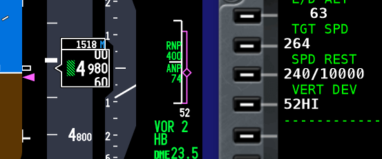
  • A white-coloured airspeed bug is displayed at V2 +15/20 on the speed tape (part of the PFD). V2+15 knots provides 40° bank capability with takeoff flaps set.   The bug is a visual aid to indicate the correct climb-out speed (bug is discussed later on).  

  • Although not required, it is a good idea is to set the minimums selector to the Acceleration Height as indicated in the CDU.  This will place a green line on the altitude tape of the PFD at the height at which the aircraft’s nose is to be lowered and flap retraction to begin.  This is a visual aid.

3.    Toggle both Flight Director (FD) switches to the O’ position (pilot flying side first).

4.    Set flaps 5 and using the electric trim switch on the yoke, trim the aircraft to the correct trim figure for takeoff. The trim figure is shown on the CDU (for example, 5.5 degrees) and is calculated dependent upon aircraft weight with passengers and fuel.  Normally the trim figure will place the trim tabs somewhere within the green band on the throttle quadrant. Takeoff should not occur if the trim tabs are outside of the green band.

5.    Arm the autothrottle (A/T) by moving the toggle on the MCP to ARM.  This may differ between airlines (when to arm the A/T) Consult the FCOM & FCTM.

6.    Release the parking brake and manually advance the thrust levers to around 40%N1.  %N1 can be airline specific with some airlines recommending 60%N1.  Consult the FCOM & FCTM.

7.    Monitor the EGT on the EICAS and when there is a decrease in EGT and the throttles are stabilised, either:

  • Advance the thrust levers to takeoff thrust (if hand flying); or,

  • Press one or both TOGA buttons if wishing the autothrottle system to be selected.  If the autothrottle system has been selected for takeoff, both thrust levers will automatically begin to advance to the correct %N1 output calculated by the Flight Management System.

Interesting Point:

  • After takeoff configuration is complete, and with the parking brake in the OFF position, some flight crews quickly advance and retard the thrust levers.  The purpose being to check for errors in the takeoff configuration.  An error will trigger the audible configuration horn when the thrust levers are advanced.

  • Become conversant with derates. Using a particular derate is normal practice, but in particular will help control over-pitching and high vertical speeds, which are a common occurrence when the aircraft is light (minimal fuel load, passengers and/or cargo).

Important Points:

  • You do not have to stop the aircraft on the runway prior to initiating 40%N1.  A rolling takeoff procedure is often recommended, as this expedites the takeoff (uses less runway length) and reduces the risk of engine damage from a foreign object being ingested into the engine (engine surge/stall due to a tailwind or crosswind).

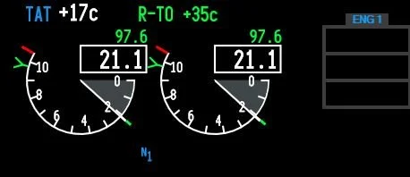
  • When the thrust has reached 40%N1, wait for it to stabilise (roughly 2-3 seconds).  Look at the N1 thrust arcs and the EGT gauge (on the EICAS display).  Both N1 arcs must be stable and the EGT values decreasing slightly.  In the real aircraft, the EGT should reduce between 10C-20C after N1 has stabilised at 40%.  If the engines are NOT allowed to stabilise, prior to advancing the thrust levers, the takeoff distance can be adversely affected.

  • There is considerable confusion around when to actually press the TOGA buttons.  As stated, %40N1 is common, but some airline procedures indicate 60%N1, while others recommend a staged approach – meaning, initially advance the thrust levers to 40%N1, allow the thrust to stabilise, and then advance the thrust levers to 70-80%N1 and press TOGA.

  • Do not push the thrust levers forward of the target %N1 - let the autothrottle do its job (otherwise you will not know if the autothrottle system has failed).  See Point 10 concerning hand placement.

  • Ensure the autothrottle has reached the target %N1 by 60 knots ground speed.  If not, execute a Rejected Takeoff (RTO).

  • Unless you select a different mode, the TOGA command mode that was engaged at takeoff (assuming you used the autothrottle system), will remain engaged until you reach the assigned altitude indicated on the MCP.

  • Selecting N1 on the MCP does not disengage TOGA mode.  If you want to disengage TOGA mode, the Flight Director switches must be toggled to the OFF position, or another vertical mode selected.

  • In some simulators that use ProSim737 software (Version 2 & 3), you will notice that when throttle arm is displayed on the PFD, the throttle will retard slightly (%N1).  This is NOT normal and is a ProSim737 software glitch.  The issue is easily resolved by moving the thrust levers forward slightly.  This glitch does not appear to cause other problems.

8.    Maintain slight forward pressure on the control column to aid in tyre adhesion to the runway. Focus on the runway approximately three-quarters in front of the aircraft.  This will assist you to maintain visual awareness and to keep the aircraft on the centreline.  Use rudder and aileron input to control any crosswind.

9.    During the initial takeoff roll, the pilot flying should place their hand on the throttle levers in readiness for a rejected takeoff (RTO).  The pilot not flying should place his hand behind the throttle levers.  Hand placement facilitates the least physical movement should an RTO be required.

10.    The pilot not flying will call out 80 Knots  Pilot flying should slowly release the pressure on the control column so that it is in the neutral position.  Soon after the aircraft will pass through the V1 speed (this speed is displayed on the speed tape).  Takeoff is mandatory at V1, and Rejected Takeoff (RTO) is now not possible.  The pilot flying, to reaffirm this decision, should remove his or her hands from the throttles; thereby, reinforcing the must fly rule.  (see important points below).

11.    At Vr (rotation), pilot not flying calls Rotate.  Pilot flying slowly and purposely initiates a smooth continuous rotation at a rate of no more than 2 to 3 degrees per second to an initial target pitch attitude of 8-10 degrees (15 degrees maximum).

Important Points:

  • Normal takeoff attitude for the 737-800 is between 8 and 10 degrees.  This provides 20 inches of tail clearance at flaps 1 and 5.  Tail contact will occur at 11 degrees of pitch (if the aircraft is still on or close to the ground).

  • Takeoff at a low thrust setting (low excess energy, low weight, etc) will result in a lower initial pitch attitude target to achieve the desired climb speed.

  • The correct takeoff attitude is achieved in approximately 3 to 4 seconds after rotation (depending on airplane weight and thrust setting).

  • Point 10 (above) discusses hand placement during the takeoff roll.  Another method used differentiates responsibility between the Captain and First Officer.  The Captain as Pilot in Command (PIC) will always have control of the thrust levers, while the pilot flying (First Officer) will concentrate solely on the takeoff with both hands on the control column.  Removal of the hand after V1 is a standard operational procedure (SOP).  This assumes that the First Officer will be pilot flying.

12.    Following takeoff, continue to raise the aircraft’s nose smoothly at a rate of no more than 2 to 3 degrees per second toward 15 degrees pitch attitude.  The Flight Director (FD) cues (pitch command bars) will probably indicate approximately 15 degrees.

Be aware that the cues provided by the Flight Director may on occasion be spurious; therefore, learn to see through the cues to the actual aircraft horizon line.

  • The Flight Director pitch command is NOT used during rotation.

13.    At this stage, you most likely will need to trim the aircraft to maintain minimum back pressure (neutral stick) on the control column.  The 737 aircraft is usually trimmed to enable flight with no pressure on the control column.  It is quite normal, following rotation, to trim down a tad to achieve neutral loading on the control column.  Do not trim during the actual rotation of the aircraft.

14.    When positive rate has been achieved, and double checked against both the actual speed the aircraft is flying at (see speed tape on PFD), and the vertical speed indicator, the pilot flying will call Gear Up and the pilot not flying will raise the gear to minimize drag and allow air speed to increase.  The pilot not flying will also announce Gear Is Up when the gear has been retracted successfully (green lights on the MIP have extinguished).

15.    The Flight Director will command a pitch to maintain an airspeed of V2 +15/20.  Follow the Flight Director cues (pitch command bar), or target a specific vertical speed.  The vertical speed will differ widely when following the FD cues as it depends on weight, fuel, derates, etc. If not using the FD, try to maintain a target vertical speed (V/S) of ~2500 feet per minute.

Important Points:

  • V2 +15/20 is the optimum climb speed with takeoff flaps (flaps 5).  It results in maximum altitude gain in the shortest distance from when the aircraft left the runway.

  • If following rotation the FD cues appear to be incorrect, or the pitch appears to be too great, ignore the FD and follow vertical speed guidance.

  • Bear in mind that vertical speed has a direct relationship to aircraft weight - if aircraft weight is low to moderate, use reduced takeoff thrust (derates) or Assumed Temperature Method to achieve a recommended vertical speed.

  • If LNAV and VNAV were selected on the MCP prior to takeoff, LNAV will provide FD inputs at 50 feet and VNAV will engage at 400 feet.

  • When VNAV is engaged, the speed of the aircraft will be automatically updated on the speed tape and the speed window on the MCP will become blank. 

  • If LNAV and VNAV have not been selected prior to takeoff, it is common practice to manually select a roll mode (LNAV) at 400 feet.  VNAV is usually selected after flaps UP.

  • If LNAV and VNAV has been selected prior to takeoff. LNAV is advisory. VNAV will automatically update the autothrottle system. The aircraft will not fly the LNAV course or the VNAV vertical profile until the autopilot is selected (CMD) on the MCP.

16.    Follow and fly the cues indicated by the FD (automation), or maintain a command speed at V2 +15/20 (hand flying) until you reach Acceleration Height (AH).  AH is often stipulated by company policy and is usually between 1000-1500 feet ASL. AH can be changed in the CDU.

17.    At or when passing through Acceleration Height, a number of tasks may need to be completed. These tasks will cause the PFD display to change.

  • The nose of the aircraft is to be lowered (pitch decreased).  This will increase airspeed and lower vertical speed.  A rough estimate to target is half the vertical speed used at takeoff. 

  • The flaps should be retracted as per the Flaps Retraction Schedule.  If noise abatement is necessary, flaps retraction may occur at the Thrust Reduction Height. 

  • As the aircraft accelerates, move the flap lever to the next detent when the airspeed passes the flap‑retraction speed for the current setting. The applicable flap detent is shown in green on the PFD speed tape.

    Example - Flaps 5 Takeoff:

    As the aircraft accelerates through the Flaps 5 detent, select Flaps 1.

    When the airspeed passes the Flaps 1 detent, select Flaps UP.

    See Interesting Points (second dot point) regarding the Speed Trend Vector).

  • Do not retract flaps unless the aircraft is accelerating, and the airspeed is at, or greater than V2 +15/20 - this ensures the speed is within the manoeuvre margin allowing for over-bank protection.  Do not retract flaps below 1000 feet RA.

  • When flaps retraction commences, the airspeed bug will disappear from the speed tape on the PFD.

  • If hand flying (VNAV not selected), at Acceleration Height set the speed in the speed window of the MCP to a speed that corresponds to the flaps UP speed.  The flaps UP speed can be found displayed on the speed tape on the PFD.  This is often referred to as Bugging Up.

  • Some flight crews when reaching Acceleration Height call Level Change, Set Top Bug.  This ensures that TOGA speed is disengaged (by selecting another mode).

  • If VNAV has been selected prior takeoff, the flaps UP speed will be automatically populated and displayed on the speed tape on the PFD.  However, the speed will not be displayed in the MCP speed window (the window will be blank).

18.    When the aircraft flies through the flaps UP speed, and after the flaps have been fully retracted, the desired climb speed is dialed into the speed window of the MCP (If VNAV is not selected).  If VNAV has been selected, the climb speed will be automatically populated and displayed on the PFD (as will the cruise speed when the aircraft reaches cruise altitude).

Important Points:

  • If VNAV is selected, the speed window in the MCP is blank.  However, if VNAV is not selected the speed window is open.

  • If automation and the autothrottle system (TOGA) is not being used, and you are hand flying the aircraft, Press N1 on the MCP (if desired) at Acceleration Height and follow FD cues to flaps UP speed. 

  • When N1 is selected, the autothrottle will control the speed of the aircraft to the N1 limit set by the FMS.  Selecting N1 ensures the aircraft has maximum power (climb thrust) in case of a single engine failure.

  • If the autothrottle system (TOGA) has been used during takeoff, N1 is automatically selected (by the FMS) at Thrust Reduction Altitude (usually ~1500 feet RA).  There is no need to press the N1 button on the MCP.

  • N1 mode doesn’t control the aircraft’s speed - it controls thrust. The autothrottle will set the maximum N1 thrust (power).  The aircraft’s speed is controlled by the pitch attitude.

  • Selecting N1 on the MCP does not provide any form of speed protection.

  • Acceleration Height can be changed in the CDU.

  • The auotpilot should NOT be engaged prior to flaps UP. This is often stipulated by airline policy,

19.    The aircraft is usually flown at a speed no faster than 250 KIAS to 10,000 feet.  At 10,000 feet, speed is usually increased to 270 KIAS. Environmental factors and/or ATC may result in differing speeds being set.

At this stage, the aircraft can be hand flown with or without VNAV and/or the autothrottle. You can either:

  • Continue to hand fly the aircraft to altitude. Appropriate climb and cruise speeds will need to be dialed into the MCP; or,

  • Select a suitable pitch and roll mode (LVL CHG, V/S, LNAV & VNAV) and engage the autopilot or select CWS. If a pitch and roll mode is selected and the autopilot not selected, the FD will provide visual cues.

20.    At 10,000 feet, dial 270 KIAS into the MCP speed window and then at 12,000 feet dial in 290 KIAS.  Follow the Flight Director cues, or if the FD is not being used, maintain roughly 2000-2500 fpm vertical speed.  At cruise altitude, transition to level flight and select on the MCP speed window 290-310 KIAS or whatever the optimum speed is (see CDU).

Interesting Points:

  • Many pilots had fly the aircraft to 10,000 feet before engaging the autopilot.  To enhance situational awareness, it is common practice, if hand flying, to have LNAV and VNAV selected. This enables the pilot to follow the navigation cues displayed on the PFD.

  • Located on the speed tape on the PFD, is a green coloured line called a Speed Trend Vector (STV).  The Speed Trend Vector will display an upwards, neutral or downwards facing arrow.  During climb-out, the Speed Trend Vector arrow can be used to determine how long it will take for the aircraft, at the current thrust setting, to reach the speed that the arrow is pointing at (usually around 10 seconds).  Therefore, when the upward arrow reaches the flaps indicator, the aircraft will pass through this flaps détente in approximately 10 seconds. The Speed Trend Vector can be used to help know when to initiate retraction of the flaps.

Summary

The above procedures are general.  Specific airline policy for a particular airline may indicate otherwise.  Likewise, there is considerable latitude to how the aircraft is flown, whether it be without automation selected, or with part or full automation selected.

It is very easy to become confused during the takeoff phase - especially in relation to automation, V speeds, acceleration heights, and how and when to change from hand flying to automation  The takeoff phase occurs quickly, there is a lot to do, and quite a bit to remember - there is little time to consult a manual or cheat sheet.

SECTION TWO:  Takeoff Guideline (LNAV, VNAV & autopilot selected prior to takeoff)

Although I have mentioned some of the VNAV procedures in the above discussion, I though it pertinent to include this section which will address a takeoff with LNAV and VNAV selected (points 1-10 below).  This information relates to FMS software U10.8A. 

Important Point:

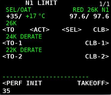
  • The aircraft requires information from the FMS when automation (LNAV & VNAV) is used.  For the takeoff to be successful, the PERF INIT and navigation data must be inputted into the CDU.

The following 10 points outline a VNAV selected takeoff:

  1. Select from the CDU a Standard Instrument Departure (SID) and press the illuminated annunciator (EXEC) on the CDU. 

  2. Verify the Flight Director switches are selected to the ON.

  3. ARM LNAV and VNAV on the MCP (press the LNAV & VNAV buttons on the MCP).

  4. ARM the Autopilot (press CMD A/B) and set the Command Speed in the speed window of the MCP to V2 (The V2 speed can be found in the takeoff page of the CDU).

  5. Takeoff (as discussed earlier).

  6. VNAV will engage at 400 feet and the Flight Director will command V2 +15/20.  The appropriate bugs on the PFD speed tape will be populated automatically.  The speed should always be crosschecked against the actual speed that the aircraft is flying and the white bug on the speed tape.

  7. At Acceleration Height (between ~1000-1500 feet RA or as indicated in the CDU) the Flight Director will command a speed 10 knots above the FLAPS UP speed.

  8. Lower the aircraft’s nose and follow the FD cues (command pitch bars).

  9. Commence FLAPS retraction and follow the Flaps Retraction Schedule (Point 18 above).

  10. As the FLAPS retract into the UP position the Flight Director will command 250 knots.

  11. Select CMD A/B (autopilot) or fly to 10,000 feet or cruise altitude and select autopilot.

SECTION THREE:  Additional Information - Summarised Important Points

Understanding %N1

To understand the various levels of automation it is important to have a relative understanding of %N1.

N1 is a measurement in percent (%) of the maximum RPM of an engine, where maximum RPM is certified at the rated power output for the engine (most simple explanation).  Therefore, 100%N1 is maximum thrust, while 0%N1 is no thrust.  (%)N1 will be at a percentage commensurate with the settings that have been inputted to the CDU (aircraft weight, fuel, derates, etc).

Important Points:

  • The autothrottle logic when TOGA selected controls the aircraft’s thrust (%N1).  The aircraft’s speed is controlled by pitch (attitude).  

  • To clarify what automated system is controlling the aircraft, always refer to the Flight Mode Annunciations (FMA) in the PFD (Refer to Table 1 for a quick overview of annunciations displayed during the takeoff).

Common Practice - What to Select For Takeoff

It is not the purpose of this article to rewrite the FCOM or FCTM.   Needless to say, there are several combinations, that can be selected at varying stages of flight.  All are at the discretion of the pilot flying, or are stipulated as part of airline policy.

After Acceleration Height has been reached, the aircraft’s nose lowered to increase speed, and the flaps retracted, it is common practice to use LVL CHG, V/S, or LNAV and VNAV, and either hand fly the aircraft, select CWS, or select the autopilot (usually at or above 3000 feet, but certainly after flaps UP) and fly to cruise altitude.

If the takeoff does not use LNAV and VNAV (not selected on the MCP) LNAV can be selected at, or after 50 feet RA and VNAV can be selected at, or after 400 feet RA.  After either of these two modes have been selected, the Flight Director cues will automatically update to reflect the data that has been inputted into the CDU.

Theoretically, a crew can hand fly the aircraft following the FD cues at V2 +15/20 to the altitude set in the MCP.  However, there will be no speed protection, and if the pitch cues recommended by the FD are not followed, then the airspeed may be either below or above the optimal setting or safety envelope.  Selecting an automation mode (not V/S) is what engages the speed protection (speed protection will be discussed shortly).

In the above scenario (assuming the aircraft is being hand flown), unless another vertical mode is selected, the aircraft will remain in TOGA command mode (thrust controlled by N1) until the altitude set in the MCP is reached.  To deselect (cancel) TOGA as the command mode, another mode such as LVL CHG, VNAV or V/S will need to be selected.  Altitude Hold (ALT HOLD) also deselects TOGA as does engaging the autopilot. 

Flight crews typically hand fly the aircraft until the flaps are retracted (flaps UP) and the aircraft is in clean configuration.  A command mode is then selected to continue the climb to cruise altitude. CWS or the autopilot may or may not be engaged.

Important Point:

  • It is important to understand what controls the various command modes.  For example, LVL CHG is controlled by N1 and pitch.  In this mode, the autothrottle will use full thrust, and the speed will be controlled by pitch.  


TABLE 1:   N1 MCP annunciation and FMA displays for common time events during takeoff and climb


TABLE 2:  Throttle command modes for common time events during takeoff and climb.  The flight crew can manually override the autothrottle logic by advancing or retarding the thrust levers by hand.  This can only be done at certain phases of flight.  Throttle online means that the crew can override the autothrottle logic, while Throttle offline means that the logic cannot be overridden


Speed Protection

One of the advantages when using the automated systems is the level of speed protection that some of the systems provide.  Speed protection means that the autothrottle logic will not allow the aircraft’s speed to be degraded to a value, by which the aircraft can stall or be below maneuvering speed.

Speed protection is not active with every automated system.  Whether speed protection is active depends upon the U version of the FMS software in use, the automation mode selected, and whether the flaps are extended or fully retracted.

  • The following examples indicate whether speed protection is available;

Level Change (LVL CHG): When you select LVL CHG, the speed window will open allowing you enter a desired speed.  LVL CHG is speed protected, meaning that the aircraft's speed will not increase beyond the speed inputted into the MCP.  This is because LVL CHG is controlled by N1 (thrust) while the aircraft’s speed is controlled by pitch.

VNAV: VNAV has active speed protection for the leading edge devices (U10.8A and above) .  This is why VNAV can be selected on the ground.

Vertical Speed (V/S): V/S provides no speed protection.  This is because V/S holds a set vertical speed.  In V/S, if you are not vigilant, you can easily encounter an overspeed or under speed situation.

N1: Selecting N1 by pressing the N1 button on the MCP (without any other mode selected) does not provide speed protection.  Using the N1 mode, only ensures maximum thrust is generated.

Important Points:

  • Speed protection is armed only for some levels of automation.

  • It is imperative that you observe the Flight Mode Annunciator (FMA) to check that the aircraft is flying the mode intended.    

ryanair taking off from bristol airport england (Adrian Pingstone)., Ryanair Boeing 737-800 (EI-DWO) takes off from Bristol Airport, England, 23Aug2014 arp, marked as public domain, more details on Wikimedia Commons)

Always Think Ahead

As stated, the takeoff phase happens quickly, especially if the aircraft’s weight is light (cargo, passengers and fuel).

Soon after rotation (Vr), the aircraft will be at Acceleration Height and beyond…  It’s important to remain vigilant and know what’s happening, and to think one step ahead of the automated system that is controlling the aircraft.  You do not want the automation to get ahead of you and hear yourself thinking what’s it doing now.

Aircraft Weight

Although briefly discussed earlier,  I would like to enlarge upon how the weight of the aircraft can have an affect on takeoff and climb.  An aircraft’s weight is altered by the volume of fuel on board, the number of passengers, and the amount of cargo carried in the holds.

In some respects, a heavily laden aircraft, although requiring higher thrust settings and longer runway length, will be more stable than the same aircraft at a lighter weight.  A lightly laden aircraft will use less runway and, unless thrust settings are managed accordingly, will be prone to an excessive rate of climb (high vertical speed and high pitch angle).  This can lead to tail strike and uncomfortably high rates of ascent.

To manage this, flight crews often limit the takeoff thrust by using one of several means.  Typically, a thrust derate is used with either CLB 1 or CLB 2 set in the CDU, or an assumed temperature thrust reduction is used.   Selecting either option will cause a longer takeoff roll (less thrust) and delay the rotation point (Vr), however, the climb-out will be less aggressive and more manageable.

Final Call

Reiterating, the above guidelines are generalist only.  Flight crews use varying methods to fly the aircraft, and often the method used will be chosen based on company policy, crew experience, aircraft weight, and other environmental factors, such as runway length, weather and winds.

Additional Information:  

Future Articles

Time permitting, other articles will be published dealing with: descent, initial approach, and landing (ILS, VNAV, Circle to Land and RNAV).

Disclaimer

The content in this post has been proof read for accuracy, however, explaining procedures that are convoluted, technical, and somewhat subjective can be challenging.  Errors on occasion present themselves.  If you observe an error (not a particular airline policy), please contact me so it can rectified.

Footnotes

(1): For example, there are different protocols between FMC U10.6 and FMC U10.8 (especially when engaging VNAV and LNAV prior to takeoff).  I have purposely not addressed these differences because they can become very confusing (another article will do this).  As at writing (2020), ProSim737 uses U10.8A.

Acronyms and Glossary

  • AFDS – Autopilot Flight Director System

  • AH - Acceleration Height.  The altitude above sea level that aircraft’s nose is lowered to gain speed for flap retraction.  AH is usually 1000 or 1500 feet and is defined by company policy.  In the US acceleration height is usually 800 feet RA

  • CDU, FMC & FMS – Control Display Unit / Flight Management Computer (term often used interchangeably).  The visual part of the Flight Management System (FMS) that enables input of variables. FMS is the system and software (U10.8A). FMC is the actual computer, and the CDU is the hardware.

  • CLB 1/2 – Climb power

  • Command Mode – The mode of automation that controls thrust

  • EICAS – Engine Indicating and Crew  Alerting System

  • F/D – Flight Director (Flight Director cues/crosshairs)

  • FMA – Flight Mode Annunciation located upper portion of Primary Flight Display (PFD)

  • KIAS – Knots Indicated Air Speed

  • LNAV – Lateral Navigation

  • LVL CHG – Level Change Command Mode

  • MCP – Mode Control Panel

  • N1 & N2 – N1 and N2 are the rotation speeds of the engine sections expressed as a percentage of a nominal value. ... The first spool is the low pressure compressor (LP), that is N1 and the second spool is the high pressure compressor (HP), that is N2. The shafts of the engine are not connected and they operate separately. Often written N1 or %N1.

  • RTO – Rejected Take Off

  • T/O Power – Takeoff power

  • Throttle On & Offline – Indicates whether the throttle is being controlled by the A/T system

  • TOGA – To Go Around Command Mode

  • TRA - Thrust Reduction Altitude.  The altitude that the engines reduce in power to increase engine longevity.  The height is usually 1500 feet; however, the altitude can be altered in CDU

  • V/S – Vertical Speed Command Mode

  • V1 – is the Go/No go speed.  You must fly after reaching V1 as a rejected take off (RTO) will not stop the aircraft before the runway ends

  • V2 – Takeoff safety speed.  The speed at which the aircraft can safely takeoff with one engine inoperative (Engine Out safe climb speed)

  • VNAV – Vertical Navigation

  • Vr – Rotation Speed.  This is the speed at which the pilot should begin pulling back on the control column to achieve a nose up pitch rate

  • Vr +15/20 – Rotation speed plus additional knots (defined by company policy)

  • Updated April 2021.

  • Updated March 2024.

  • Updated February 2025.

Crosswind Landing Techniques Part Two - Calculations

crosswind landing with right main gear touching first (Jeroen Stroes Aviation Photography from Netherlands, EI-FIZ (27608888537), CC BY 2.0

Determining Correct Landing Speed (Vref)

Vref is defined as landing speed or the threshold crossing speed, while Vapp is defined as the approach speed with wind/gust additives.

When landing with a headwind, crosswind, or tailwind the Vref and Vapp must be adjusted accordingly to obtain the optimal speed at the time of touchdown.  Failure to do this may result in the aircraft landing at an non-optimal speed causing runway overshoot, stall, or floating (ground affect).

Mathematical calculations can be used to determine Vref and Vapp based on wind speed, direction, and gusts.

This is the second segment of a two-segment post.  The first segment dealt with methods used to land in cross wind conditions  - Crosswind Landing Techniques Part One Crab and Sideslip.

Normal Conditions

When using the autothrottle is to be used for landing, position command speed to Vref+5 knots. There is no need to add the wind additive as the autothrottle logic already compensates for gusts through airspeed and acceleration sensing.

If the autothrottle is disengaged or is planned to be disengaged prior to landing, the recommended method to obtain the correct approach speed (Vapp), is to add one half of the reported steady headwind component plus the full gust increment above the steady wind to the reference speed (Vref).

One half of the reported steady headwind component can be estimated by using 50% for a direct headwind, 35% for a 45-degree crosswind, zero for a direct crosswind, or interpolation between.

When making adjustments for wind additives, the maximum command speed should not exceed Vref+20 knots or landing flap placard speed minus 5 knots, whichever is lower.

The minimum command speed setting with autothrottle disconnected is Vref+5 knots.  The gust correction should be maintained to touchdown while the steady headwind correction should be bled off as the airplane approaches touchdown. 

It is important to note that Vref+5 knots is the speed that is desired when crossing the threshold of the runway - it is NOT the approach speed.  The approach speed (Vapp) is determined by headwind with/without gusts.  If the wind is calm, Vref+5 knots will equal Vapp.

When landing in a tailwind, do not apply wind corrections. Set command speed at Vref+5 knots (autothrottle engaged or not engaged).

Non-Normal Conditions

When Vref has been adjusted by the non-normal procedure, the new Vref is called the adjusted Vref and is used for the landing.  To this speed is added the wind component (if necessary).

For example, if a non-normal checklist specifies 'Use flaps 15 and Vref 15+10 for landing', the flight crew would select flaps 15 and look up the Vref 15 speed (in FCTM or QRH) and add 10 knots to that speed.  The adjusted Vref does not include wind corrections and these will need to be added.

If the autothrottle is disengaged, or is planned to be disengaged prior to landing, appropriate wind corrections must be added to the adjusted Vref to arrive at command speed.  Command speed is the safest speed used to fly the approach (Vapp).  If the speed is above command speed then it will need to be bleed off prior to touchdown.

Autoland Limitations

If using autoland (CAT II & CAT IIIA) the autothrottle remains engaged and the command speed is set to Vref+5.

The following autoland limitations must be complied with:

  1. Glide slope angle tolerance - maximum 3.25 degrees / minimum 2.5 degrees;

  2. Engines 1/2 operational;

  3. Maximum​ tailwind - 15 kts​;

  4. Maximum headwind - 25 kts​;

  5. Maximum crosswind - 20​ kts ;

  6. Maximum tailwind at flaps 30 - 12 knots (winglets); and,

  7. Landing in gusty​ wind​ or windshear​ conditions is not approved during CAT II and CAT IIIA operations.

Guideline (an easy way to remember the above - cheat sheet)

This information assumes the autothrottle will be disengaged prior to landing.

  • Headwind less than 10 knots:  Vref+5

  • Headwind greater than 10 knots:  Vref +headwind / 2 (half your headwind) - This is your Vref

  • If Vref is > 20 knots, then:  Vref+20 (as per placard guide)

With Gusts

  • Formula (Wind < 10 knots):  Vref+5 + gust – headwind

  • Formula (Wind > 10 knots):  Vref + headwind/2 (half your headwind) + gust – headwind

Calculating Directional Wind

A wind component will not always be at 90 Degrees or straight on to your landing direction.  The following calculation is often used to determine the directional component.  One half of the reported steady headwind component can be estimated by using 50% for a direct headwind, 35% for 45 degree crosswind, zero for a direct crosswind and interpolation in between.

Tail Winds

Tail winds are very challenging for conducting a stabilized approach.  Because of the increased ground speed caused by a tail wind, Boeing does not publish Vref correction factors for tail winds. 

Typically, to maintain the proper approach speed and rate of descent while maintaining glide slope, thrust must be decreased which minimizes the available safety envelope should a go-around be required.  If a go-around is required, precious seconds might be lost as the engines accelerate; the aircraft would continue to descend and might touch down on the runway before the engines produce enough thrust to enable a climb.

The International Civil Aviation Organization (ICAO) recommends that the tail wind component must not exceed 5 knots plus gusts on a designated runway; however, adherence to this recommendation varies among members.  Several airlines have been certified for operation with a 15 knot tailwind. 

In the United States, Federal Aviation Administration (FAA) sets the tail wind component limit for runways that are clear and dry at 5 knots, and in some circumstances 7 knots, however FAA allows no tail wind component when runways are not clear and dry.  Note, that many manuals subscribe to the 10 knots no tailwind rule (see table below).

Crosswind components can be variable dependent upon flight crew discretion and airline policy; therefore, the above is to be used as a 'guide' only.

The below table (limitations) summarizes much of what has been written above.


table 1: wind limits for 737-800. the table provides a good summary of what has been written in the article


The CDU if configured correctly can provide information concerning wind components.  Press the key on the CDU named 'PROG' followed by 'PREV PAGE'.  This page provides an overview of the wind component including head, tail and crosswind.

Wind Correction Field (WIN CORR)

The approach page in the CDU has a field named WIN CORR (Wind Correction Field or WCF).  Using this field, a flight crew can alter the Vref+ speed (additive) that is used by the autothrottle.  The default reading is +5.   Any change will alter how the FMC calculates the command speed that the autothrottle uses; changes are reflected in the LEGS page.  It's important to update the WIND CORR field if VNAV is used for the approach, as VNAV uses data from the FMC to fly the approach.  If hand flying the aircraft, it's often easier to to add the Vref additive to the speed window in the MCP.

WIND CORR Explained

The WCF is a handy feature if a flight crew wishes to increase the safety margin the autothrottle algorithm operates.

Boeing when they designed the autothrottle algorithm programmed a speed additive that the A/T automatically adds to Vref when the A/T is engaged.  The reason for adding this speed is to provide a safety buffer to ensure that the A/T does not command a speed equal to or lower than Vref.   (recall that wind gusts can cause the autothrottle to spool up or down depending upon the gust strength).  

A Vref+ speed higher than +5 can be inputted when gusty or headwind conditions are above what are considered normal.  By increasing the +speed, the  speed commanded by the autothrottle will not degrade to a speed lower than that inputted.

Important Points:

  • During the approach, V speeds are important to maintain.  A commanded speed that is below optimal can be dangerous, especially if the crew needs to conduct a go-around, or if winds suddenly increase or decrease.  An increase or decrease in wind can cause pitch coupling.

  • If using VNAV, it's important to update the WIND CORR field to the correct headwind speed based on conditions.  This is because VNAV uses the data from the FMC.

If executing an autoland (rarely done in the B737), the WIND CORR field is left as +5 knots (default).  The autoland and autothrottle will command the correct approach and landing speed.

Crosswind Landing Techniques Part One - Crab and Sideslip


This video very clearly illustrates my point that landing in a strong crosswind can be a challenging and in some cases downright dangerous (Video © CargoSpotter (with thanks); courtesy U-Tube).

Generally, flight crews use one of two techniques or a combination thereof to approach and land in crosswind conditions.  If winds exceed aircraft tolerances, which in the 737-800 is 33 knots (winglets) and 36 knots (no winglets), the flight crew will divert to their alternate airport (Brady, Chris - The Boeing 737 technical Guide).

crab approach. Wind is right to left at 16 knots with aircraft crabbing into the wind to maintain centerline approach course.  Just before flare, left rudder will be applied to correct for drift to bring aircraft into line with centerline of runway.  This technique is called 'de-crabbing’. During such an approach, the right wing may also be lowered 'a tad' (cross-control) to ensure that the aircraft maintains the correct alignment and is not blown of course by a 'too-early de-crab'.  Right wing down also ensures the main gear adheres to the runway during the roll out

Maximum crosswind figures can differ between airlines and often it's left to the pilot's discretion and experience.  Below is an excerpt from the Landing Crosswind Guidelines from the Flight Crew Training Manual (FCTM).  Note that FCTMs can differ depending on date of publication.

There are several factors that require careful consideration before selecting an appropriate crosswind technique: the geometry of the aircraft (engine and wing-tip contact and tail-strike contact), the roll and yaw authority of the aircraft, and the magnitude of the crosswind component.  Consideration also needs to be made concerning the effect of the selected technique when the aircraft is flared to land.

Crosswind Approach and Landing Techniques

There are four techniques used during the approach and landing phase which center around the crab and sideslip approach.  The crab and sideslip are the primary methods and most commonly used while the de-crab and combination crab-sideslip are subsets that can be used when crosswinds are stronger than usual.

It must be remembered that whatever method is used it is at the discretion of the pilot in command.

  1. Crab (to touchdown).

  2. Sideslip (wing low).

  3. De-crab during flare.

  4. Combination crab and sideslip.

1:  Crab (to touchdown)

  • Airplane maintains a crab during the final approach phase.

  • Airplane touches down in crab.

  • Flight deck is over upwind side of runway (Main gear is on runway center).

  • Airplane will de-crab at touchdown.

  • Flight crew must maintain directional control during roll out with rudder and aileron.

With wings level, the crew will use drift correction to counter the effect of the crosswind during approach.  Drift correction will cause the aircraft to be pointing in a direction either left or right of the runway heading, however, the forward energy of the aircraft will be towards the centerline.  This is called the crab because the aircraft is crabbing at an angle left or right of the aircraft's primary heading.

Most jetliners have the ability to land in a crab, however, it must be remembered that landing in a crab places considerable stress on the main landing gear and tyre side-walls, which in turn can cause issues with tyre and wheel damage, not too mention directional control.

The later is caused by the tandem arrangement of the main landing gear that has a strong tendency to travel in the direction that the nose of the aircraft is pointing at the moment of touchdown.  This can result in the aircraft travelling toward the edge of the runway during the roll out.  To counter this, and align the nose of the aircraft with the centreline of the runway, the pilot flying must apply rudder input when lowering the nose wheel to the runway surface.

A reference to the maximum amount of crab that can be safely applied in the B737 was not found, other than maximum crosswind guidelines must not be exceeded.  The crab touchdown technique is the preferred choice if the runway is wet.

2:  Sideslip (wing low)

  • Upwind wing lowered into wind.

  • Opposite rudder (downwind direction) maintains runway alignment.

  • In a sideslip the aircraft will be directly aligned with the runway centerline using a combination of into-wind aileron and opposite rudder control (called cross-controls) to correct the crosswind drift.

The pilot flying establishes a steady sideslip (on final approach by applying downwind rudder to align the airplane with the runway centerline and upwind aileron to lower the wing into the wind to prevent drift.  The upwind wheels should touch down before the downwind wheels touch down.

The sideslip technique reduces the maximum crosswind capability based on a 2/3 ratio leaving the last third for gusts.  However, a possible problem associated with this approach technique is that gusty conditions during the final phase of the landing may preempt a nacelle or wing strike on the runway.

Therefore a sideslip landing is not recommended when the crosswind component is in excess of 17 knots at flaps 15, 20 and 30, or 23 knots at flaps 40.

The sideslip approach and landing can be challenging both mentally and physically on the pilot flying and it  is often difficult to maintain the cross control coordination through the final phase of the approach to touchdown.  If the flight crew elects to fly the sideslip to touchdown, it may also be necessary to add a crab during strong crosswinds.

3:  De-crab During Flare(with removal of crab during flare)

  • Maintain crab on the approach.

  • At ~100 foot AGL the flight crew will de-crab the aircraft; and,

  • During the flare, apply rudder to align airplane with runway centreline and, if required slight opposite aileron to keep the wings level and stop roll.

This technique is probably the most common technique used and is often referred to as the 'crab-de-crab'.

The crab technique involves establishing a wings level crab angle on final approach that is sufficient to track the extended runway centerline.  At approximately 100 foot AGL and during the flare the throttles are reduced to idle and downwind rudder is applied to align the aircraft with the centerline (de-crab). 

Depending upon the strength of the crosswind, the aircraft may yaw when the rudder is applied causing the aircraft to roll.  if this occurs, the upwind aileron must be placed into the wind and the touchdown maintained with crossed controls to maintain wings level (this then becomes a combination crab/sideslip - point 4).

Upwind aileron control is important, as a moderate crosswind may generate lift by targeting the underside of the wing. Upwind aileron control assists in ensuring positive adhesion of the landing gear to the runway on the upwind side of the aircraft as the wind causes the wing to be pushed downwards toward the ground.

Applied correctly, this technique results in the airplane touching down simultaneously on both main landing gear with the airplane aligned with the runway centerline.

4:  Combination Crab and Sideslip

  • De-crab using rudder to align aircraft with runway (same as point 3 de crab during flare).

  • Application of opposite aileron to keep the wings level and stop roll (sideslip). 

The technique is to maintain the approach in a crab, then during the final stages of the approach and flare increase the into-wind aileron and land on the upwind tyre with the upwind wing slightly low.  The combination of into-wind aileron and opposite rudder control means that the flight crew will be landing with cross-controls.

The combination of crab and sideslip is used to counter against the turbulence often associated with stronger than normal crosswinds.

As with the sideslip method, there is the possibility of a nacelle or wing strike should a strong gust occur during the final landing phase, especially with aircraft in which the engines are mounted beneath the wings.

FIGURE 1:  Diagram showing most commonly used approach techniques (copyright Boeing)

Operational Requirements and Handling Techniques

With a relatively light crosswind (15-20 knot crosswind component), a safe crosswind landing can be conducted with either; a steady sideslip (no crab) or a wings level, with no de-crab prior to touchdown.

With a strong crosswind (above a 15 to 20 knot crosswind component), a safe crosswind landing requires a crabbed approach and a partial de-crab prior to touchdown.

For most transport category aircraft, touching down with a five-degree crab angle with an associated five-degree wing bank angle is a typical technique in strong crosswinds.

The choice of handling technique is subjective and is based on the prevailing crosswind component and on factors such as; wind gusts, runway length and surface condition, aircraft type and weight, and crew experience.

Touchdown Recommendations

No matter which technique used for landing in a crosswind, after the main landing gear touches down and the wheels begin to rotate, the aircraft is influenced by the laws of ground dynamics.

Effect of Wind Striking the Fuselage, Use of Reverse Thrust and Effect of Braking

The side force created by a crosswind striking the fuselage and control surfaces tends to cause the aircraft to skid sideways off the centerline.  This can make directional control challenging.

Reverse Thrust

The effects of applying the reverse thrust, especially during a crab ‘only’ landing can cause additional direction forces.  Reverse thrust will apply a stopping force aligned with the aircraft’s direction of travel (the engines point in the same direction as the nose of the aircraft).  This force increases the aircraft’s tendency to skid sideways.

Effects of Braking

Autobrakes operate by the amount of direct pressure applied to the wheels.  In a strong crosswind landing, it is common practice to use a combination of crab and sideslip to land the aircraft on the centerline.  Sideslip and cross-control causes the upwind wing to be slightly down upon landing and this procedure is carried through the landing roll to control directional movement of the aircraft. 

The extra pressure applied to the ‘wing-down’ landing gear causes increased auto-braking force to be applied which creates the tendency of the aircraft to turn into the wind during the landing roll.  Therefore, a flight crew must be vigilant and be prepared to counter this unwanted directional force.

If the runway is contaminated and contamination is not evenly distributed, the anti-skid system may prematurely release the brakes on one side causing further directional movement.

FIGURE 2:  Diagram showing recovery of a skid caused by crosswind and reverse thrust side forces (source: Flight Safety Foundation ALAR Task Force)

Maintaining Control - braking and reverse thrust

If the aircraft tends to skew towards the side from higher than normal wheel-braking force, the flight crew should release the brakes (disengage autobrake) which will minimize directional movement.  

To counter against the directional movement caused by application of reverse thrust, a crew can select reverse idle thrust which effectively cancels the side-force component.  When the centerline has been recaptured, toe brakes can be applied and reverse thrust reactivated.

Runway Selection and Environmental Conditions

If the airport has more than one runway, the flight crew should land the airplane on the runway that has the most favourable wind conditions.  Nevertheless, factors such as airport maintenance or noise abatement procedures sometime preclude this.

I have not discussed environmental considerations which come into play if the runway is wet, slippery or covered in light snow (contaminated).  Contaminated conditions further reduce (usually by 5 knots) the crosswind component that an aircraft can land.

Determining Correct Landing Speed (Vref)

Vref is defined as landing speed or threshold crossing speed.

When landing with a headwind, crosswind, or tailwind the Vref must be adjusted accordingly to obtain the optimal speed at the time of touchdown.  Additionally the choice to use or not use autothrottle must be considered. Failure to do this may result in the aircraft landing at a non-optimal speed causing runway overshoot, stall, or floating (ground affect).

This article is part one of two posts.  The second post addresses the calculations required to safety land in crosswind conditions: Crosswind Landing Techniques Part Two Calculations.

Approach Tools: Vertical Bearing Indicator, Altitude Range Arc and Vertical Deviation Scale

  • THIS ARTICLE IS UNDER REVIEW - EXPECT MINOR CHANGES…. (9 September 2025)

On 12 February 2012, the flight crew of a Boeing 737 aircraft, registered VH-TJS and operated by Qantas Airways Limited, was conducting a scheduled passenger service from Sydney, New South Wales to Canberra, Australian Capital Territory. Due to scheduled maintenance the instrument landing system at Canberra was not available and the crew prepared for an alternate instrument approach that provided for lateral but not vertical flight path information. The flight was at night with rain showers and scattered cloud in the Canberra area.

Shortly after becoming established on the final approach course with the aircraft’s automatic flight system engaged, the flight crew descended below the minimum safe altitude for that stage of the approach. The crew identified the deviation and leveled the aircraft until the correct descent profile was intercepted, then continued the approach and landed. No enhanced ground proximity warning system alerts were generated, as the alerting thresholds were not exceeded.

During those phases of flight when terrain clearance is unavoidably reduced, such as during departure and approach, situation awareness is particularly crucial. Any loss of vertical situation awareness increases the risk of controlled flight into terrain. This occurrence highlights the importance of crews effectively monitoring their aircraft’s flight profile to ensure that descent is not continued through an intermediate step-down altitude when conducting a non-precision approach (Australian Transport safety Bureau, 2013).

Determining the correct rate of descent (RoD) or vertical speed (V/S) is a critical attribute if an aircraft is to arrive at the correct altitude and avoid excessive descent rates.  Control of the vertical path uses two different methods: the step-down method and the constant descent method.  Both methods assume that the aircraft is being flown in landing configuration at the final approach speed (VaPP) from the final approach fix (FAF) to the landing initiation of the missed approach.

Non Precision Approaches (NPA)

Historically, non precision approaches reference ground navigation aids that exhibit a degree of inaccuracy, which is often enhanced by the poorly defined vertical path published on an approach chart; NPA charts typically provide only an assigned altitude at the FAF and the distance from the FAF to the MAP.  Thus, flight crew awareness of the aircraft’s vertical position versus the intended vertical path of the final approach can be quite low when executing traditional style step-down approaches.

Flight crews today, especially those flying in and out of busy intercity hubs, rarely execute step down approaches as computer and GPS-orientated systems have replaced traditional methods of navigation.  However, as the flight into Canberra revealed, the best system may at times be inoperative or fail and it is good airmanship to understand and be able to remember one or more of the below- mentioned equations. 

Today's avionics systems provide a high level of redundancy and the Boeing 737-800 NG incorporates a number of integrated aids to assist a flight crew during descent and approach.  In this article, I will discuss the following:

  • Calculations to determine rate of descent and glide path;

  • Vertical Bearing Indicator (VBI);

  • Altitude Range Arc; and,

  • Vertical Development (VERT DEV).

Rate of Descent & Glideslope Calculations

To determine the best vertical speed to use during a non precision approach, flight crews regularly use a number of 'back of the envelope' calculations to determine rate of descent and glide path – some more accurate than others.  Search ‘determine descent rate’ in Google.  Some of the more commonly used rules of thumb are:

  • Divide your ground speed by 2, then add a zero (120 kias / 2 = 60, add 0 = 600 fpm).

  • Rate of descent (RoD) in ft/min should be equal to 5 times the ground speed in knots (same as above but different calculation).

  • To maintain a stabilized approach, add a zero to your indicated air speed and divide by two (150 kias + 0 = 1500 / 2 = 750 fpm).

  • To determine distance from threshold to start a 3 degree glideslope, take the height above ground level and divide by three hundred (600 ft AGL / 300 = 2 nm).

  • To maintain a 3 degree glideslope (ILS), multiply your ground speed by 5.  The resulting number is the rate of descent to fly (110 kias x 5 + 550 fpm on 3 degree glideslope).

  • If the glideslope is not operational on an ILS approach with DME, multiply the distance ‘to go’ by 300.  This will provide the height in feet above the threshold of the runway (4 nm to the threshold; multiply x 300 = 1200 ft).

CDU showing DES Page, waypoint/altitude and VBI interface (Key RSK3 & RSK4)

Vertical Bearing Indicator (VBI)

A tool often overlooked with regard to positional awareness is the Vertical Bearing Indicator (VBI). The VBI display is part of the Descent page in the CDU. 

Reading through the literature there is very little application of this tool published in the Flight Crew Training Manual (FCTM). What information that is available comes from real world line pilot experience and through aftermarket publications such as the FMC Users Guide by Bill Bulfer.

Before continuing, flight simulation avionics packages can differ; often these differences reflect on the flight management software used (U number), however, sometimes the software has not been modeled correctly. The information in this article reflects the real avionics suite used in the 737.

The VBI can calculate an accurate rate of descent to a particular spatial point.  It is basically an angle calculator that provides ‘live’ vertical speed information based upon a desired descent angle, the current speed of the aircraft and an end location. The VBI can interrogate information from any navigation source whether it be a waypoint, point along route waypoint, nav aid, such as a VOR, or runway designation.

The application of the VBI is varied, however, in its simplest application, the flight crew enters into the VBI a waypoint and final altitude that the aircraft should be at, for example, the Initial Approach or Final Approach Fix could be used or perhaps the landing runway threshold. This figure is determined by consulting the appropriate approach chart for the airport.  Once the information is imported into the VBI, the FMC will calculate the descent rate based on flight variables.  As the aircraft descends, the VBI readout will continually update the descent rate based upon aircraft speed and rate of descent.

The flight crew can either manually fly the aircraft using the descent rate information as a guide, or use part or full automation to maintain the rate of descent.  A common method is to use the Vertical Speed (V/S) function in the MCP.

It is important to understand that the VBI has nothing to do with VNAV; the VBI will function no matter if VNAV is selected or not.  The VBI takes the raw distance between the aircraft and a selected altitude point and calculates a vertical bearing to that point.  If that point is part of a route in the CDU, then the next altitude constraint will be displayed, unless the user changes this.

If a route has not been programmed into the CDU, or a point in space along the route is required that is not a waypoint, then the waypoint will need to be created using the FIX page in the CDU. To learn how do do this see: Creating Waypoints On The Fly.

The VBI provides 3 fields:

  • FPA (Flight Plan Angle) is the vertical path in degrees that the aircraft is currently flying.

  • V/B (Vertical Bearing) is the vertical path in degrees that the aircraft SHOULD be flying to reach the imported waypoint at the desired altitude.

  • V/S (Vertical Speed) is the vertical bearing (V/B) converted into vertical speed for easy input into the V/S window in the MCP.

The VBI can be used in a number of scenarios and, once its fullest potential is understood, can be used along with the FIX function in the CDU to create additional waypoints and interception points from which descent data can be obtained. Possible scenarios that the VBI can be used are in a:

  • Approach from downwind;

  • Approach from base;

  • Straight-in approach;

  • Circling Approach;

  • Arc approach; and,

  • Descent from altitude to a waypoint, Initial Approach Fix (IAF) or Final Approach Fix (FAF).

One of the main advantages in using the VBI is that the pilot can instigate an accurate controlled idle descent, following a desired glide path to the desired waypoint.

Accessing the VBI

Navigate to Descent page in the CDU by pressing the DES key.

At lower right hand side of the DES page you will see the following: FPA, V/B, V/S.  This is the Vertical Bearing Indicator.

Key RSK3 (right line select 3) allows manual entry of a waypoint and altitude or altitude.  There are a few ways to import the data to the VBI. Either:

  1. Type the waypoint and altitude separated by the / slash symbol into the scratchpad of the CDU and upload to the correct line. An example being BUSKA/4200, or if desiring the landing runway RWxx followed by a forward slash (RWxx/) or RWxx followed immediately by /-0.1 (RWxx/-0.1) - which is used depends on the avionics software in use. The forward slash (/) enables the VBI to auto-populate the altitude with the touchdown zone elevation (TSZE) for the runway ); or,

  2. Opening the LEGS page select the appropriate waypoint wanted, download this to the scratchpad and then upload the information directly to the VBI. The same procedure is used to insert the landing runway.

  3. If an along route waypoint has been created in the FIX page, then this information will need to be downloaded to the scratchpad and then uploads to the VBI.

Important Points:

  • The information and navigation data that can be displayed by the VBI (both in the CDU and ND) is paramount in enhancing spacial awareness, especially for approaches that are not straight-in.

  • There are several ways that the VBI can be used. I urge you to experiment.

  • The VBI is a straightforward to tool to use once you have an understanding of the three variables (flight path, vertical bearing and vertical speed).

Using The VBI (for example to change altitude)

  1. Enter the required information into the VBI (waypoint and altitude - WPT/ALT).

  2. Watch the V/B and wait until the V/B moves between 2.7 and 3.0 degrees (or whatever descent angle you require).

  3. When the value is displayed in the VBI, dial the new altitude and V/S into the MCP. The Autopilot, if selected, will follow the V/S.

  4. If VNAV is selected, and a VNAV descent is commanded prior to reaching the Top of Descent (ToD), the Flight Management System (FMS) will command a 1250 fpm descent rate until the displayed V/B is captured before following the vertical bearing.

An Introduction to VBI (courtesy 737 Captain A. Asiri, U-Tube)

The VBI can also be used during the approach. Insert the landing runway information into the VBI, for example, RWxx and the VBI will update the flight path angle, vertical bearing and vertical speed to the runway. The vertical speed information can be dialed directly into V/S in the MCP or it can be used solely as a reference if hand flying the aircraft.

The runway information can either be downloaded to the scratchpad in the CDU by selecting the RWxx in the LEGS page, and then uploading to the VBI, or the information can be typed into the scratchpad and uploaded separately. If the later is used, type the runway number followed by a forward slash. For example, RW12/.

Important Points:

  • The idle descent in a 737 is roughly 3.0 degrees.

  • The VBI can be used for any waypoint, fix and altitude and acts in conjunction with the AFDS

  • The vertical bearing when the aircraft is on final approach calculates data from the Final Approach Fix (FAF) to the runway threshold.

VBI and ProSim737

It has been mentioned that the VBI may function differently between avionics suites (U number) and software manufacturers. At the moment, ProSim737 (as at September 2024 running Version 3.24b29) does not replicate fully the functionality of the VBI. The WPT/ALT should be able to be overwritten at anytime during a flight. ProSim737 does not do this. Instead, the WPT/ALT can only be overwritten when the Vertical Deviation Scale (VDS) is displayed on the ND. This usually occurs when the aircraft has reached Top of Descent (ToD).

I assume that this shortfall will be rectified in upcoming releases.

737-800 Altitude Range Arc and Vertical Deviation Scale with Pointer. Hi / Low numbers are not displayed as aircraft is on target for vertical descent

Altitude Range Arc (ARA)

A helpful feature often overlooked is the Altitude Range Arc (ARA).  The ARA is a green coloured half semicircle which can be viewed on the Navigation Display (ND).  The ARA indicates the approximate position on the map where the altitude, as set on the MCP is expected to be reached. 

The ARA will be displayed whenever the altitude has been changed in the MCP and a descent mode selected (for example, Level Change or V/S).

Initially the line will advance and contract, but once the aircraft is established on the descent profile the semicircle should come to rest on the next targeted waypoint.  

Important Point:

  • The ARA is a reference to the approximate position that the aircraft will be at if conditions remain as they are. It is guide.

Vertical Deviation Scale and Pointer (VDS) & Vertical Development (VERT DEV)

The Vertical Deviation Scale is another feature often misunderstood.  The scale can be found on the lower right hand side of the Navigation Display (ND). The scale is also duplicated on the Primary Flight Display (PFD). The scale is often cross referenced to Vertical Development (see below).

Montage showing Vertical Deviation Scale & vertical development display on PFD, ND and CDU respectively

The VDS is a solid white-coloured vertical line with three smaller horizontal lines at the upper, lower and middle section, on which a travelling magenta-coloured diamond is superimposed.  The middle horizontal line represents the aircraft’s position and the travelling diamond represents the vertical bearing (V/B). 

The VDS display represents the aircraft’s vertical deviation from the FMC’s determined descent path (vertical bearing) within +- 400 feet.  It operates in a similar way to the Glideslope Deviation Scale on the Instrument Landing System (ILS).

When the aircraft is within +- 400 feet of the vertical bearing, the diamond will begin to move, indicating that the aircraft is above, below or on the V/B target.  When the aircraft is on target (middle horizontal line), the FMA will annunciate IDLE thrust mode followed by THR HLD as the aircraft pitches downwards to maintain the vertical bearing to the next waypoint.

Important Point:

  • For the VDS to be displayed, a descent and approach profile must be selected from the CDU. The VDS will be displayed no matter what type of approach is used (RNAV, VNAV, VOR, etc).

In some literature this tool is referred to as the Vertical Track Indicator (VTI).

Vertical Development (VERT DEV)

Vertical Deviation Scale and Vertical Development in PFD, ND and CDU

The Vertical Development (VERT DEV) display can be found in the Descent page in the CDU. The displayed number is the numerical equivalent of the Vertical Deviation Scale.  The Vertical Development will display HI or LO prefixed by a number which is the feet the aircraft is above or below the desired glide path; the number will be displayed after the discrepancy has exceeded 50 feet. This information is also duplicated by the display of white-coloured numerals beneath the Vertical Development Scale in the ND.

The Vertical Deviation Scale and Vertical Development display will remain visible on the PFD, ND and CDU throughout the approach. Both tools are important aids to cross reference during a Non Precision Approach (NPA). 

Additional Information

Final Call

The traditional method of a step down approach, which was the mainstay used in the 1970s has evolved with the use of computer systems and GPS.  In the 1980s RNAV (area navigation) approaches with point to point trajectories began to be used, and in the 1990s these approach procedures were further enhanced with the use of Required Navigational Performance (RNP) in which an aircraft is able to fly the RNAV approach trajectory and meet specified Actual Navigation Performance (ANP) and RNP criteria.  From the 1990s onward with the advent of GPS, the method that non precision approaches are flown has allowed full implementation of the RNP concept with a high degree of accuracy.

Although the nature of non precision approaches has evolved to that of a 'precision-like' approach with a constant descent angle, their are operators that widely use these techniques, despite their flaws, weaknesses and drawbacks. Even if modern navigational concepts are used in conjunction with traditional methods, aids such as the Vertical Bearing Indicator, Altitude Range Arc and the Vertical Development display should not be overlooked.  Appropriate cross checking of the data supplied by these aids provides an added safety envelope and avoids having to remember, calculate and rely on ‘back of the envelope’ calculations.

The flight crew landing in Canberra, Australia did not use all the available aids at their disposal.  If they had, the loss of vertical situational awareness may not have occurred.

  • UPDATED: 02 September 2025

Abbreviations

  • ALT - Altitude

  • ANP - Actual Navigation Performance

  • ARA - Altitude Range Arc

  • CDU – Control Display Unit (used by the flight crew to interface the with the FMC)

  • FAF - Final Approach Fix

  • FMS – Flight Management System

  • FMA – Flight Mode Annunciation

  • FMC – Flight Management Computer (connects to two CDU units)

  • ILS – Instrument Landing System

  • KIAS - Knots Indicated Air Speed

  • MAP - Missed Approach Point

  • MCP – Mode Control Panel

  • ND – Navigation Display

  • NPA – Non Precision Approach

  • RoD – Rate of Descent

  • RNP - Required Navigation Performance

  • RNAV - Area Navigation

  • TDZE - Touchdown Zone Elevation (runway threshold)

  • ToD – Top of Descent

  • V/B – Vertical Bearing

  • VBI – Vertical Bearing Indicator

  • V/S – Vertical Speed

  • VDS – Vertical Deviation Scale and pointer (also called Vertical Track Indicator)

  • VERT DEV – Vertical Development

  • WPT - Waypoint

Changing Pilot Automation Dependency

Cp Flight MCP

Although this website primarily discusses construction and flying techniques of the Boeing 737, I believe it's pertinent to include articles that relate to flying in general and have merit to both real-time aviators and virtual pilots.

This article supplements an article that discusses the Speed, VNAV and Altitude Intervention (INTV) system.

Rather than create a link to an interesting article which may at some stage be removed, I’ve copied the article verbatim below.  The article which came from Aviation Week Space and Technology is a little long, but well worth a read.

How To End Pilot Automation Dependency

It is foolhardy to draw hasty conclusions about accidents. The investigation into the cause of the Asiana 214 Boeing 777-200ER crash at San Francisco International Airport on July 6 is still in its early stages. While it is not clear exactly how crew performance figured into the accident that claimed three lives, we believe that there is no excuse for landing short on a calm, clear day in a fully functioning jetliner. If the NTSB determines that the 777-200ER ‘s engines and systems were working properly, then how could the Asiana pilots have gotten themselves into that jam?

It may be that the crew was acting primarily as “automation managers” and not remaining sufficiently engaged in actively flying the airplane. It would not be the first time that this has been a factor in an accident . In the final 2.5 min. of the flight, the NTSB says, “multiple autopilot modes and multiple autothrottle modes” were inputted—all while airspeed was allowed to drop far below the 137-kt. target. It also may turn out that software rules governing interaction of the autopilot and autothrottle in the 777 are not intuitive under some settings and problematic for landing (see page 25). But that would be no excuse for flying into the ground.

On balance, automation has been a major contributor to the safer, more efficient operation of airliners. But automation has not reached the point where it can handle all contingencies. We have not arrived at the point alluded to in the joke about the crew of the future being a pilot and a dog (the pilot is there to feed the dog, the dog is there to bite the pilot if he touches the controls). So humans must be prepared to hand-fly an aircraft at any point .

For years now, concern has been growing that airline pilot's basic stick, rudder and energy management skills are becoming weak due to over-reliance on automation systems. Pilots have become, in the words of Capt. Warren VanderBurgh of American Airlines dependent upon computers that generate the purple-pink cues on cockpit displays.

There is nothing inherently risky about using automation, he explains in a famous lecture, but there is a paradox about automation that crews must be aware of: In most situations, automation reduces workload. But in some situations, especially when time is critical, automation increases workload. For example, it is harder to rapidly and correctly reprogram a flight-management computer to avoid a midair collision than it is to turn off automated systems, grab the controls and take evasive action on one’s own.

This addiction to automation is particularly troubling because of the rapid growth of the international airline industry in the last two decades, notably in Asia and the Middle East. Many nations, including South Korea, do not have robust general aviation, light air freight and commuter airline sectors where pilots can amass hundreds of hand-flown takeoffs and departures, arrivals and landings before graduating to the cockpit of an Airbus or a Boeing airplane carrying scores of passengers.

In the wake of the Asiana crash , Tom Brown, a retired United Airlines 747-400 standards captain and former instructor of Asiana pilots , said in an email to friends that while he worked in South Korea, he “was shocked and surprised by the lack of basic piloting skills.” Requiring pilots “to shoot a visual approach struck fear into their hearts.”

Other expatriate training pilots who have worked in Asia and the Middle East tell similar stories about lack of basic head-up airmanship skills and preoccupation with head-down button pushing. They can perfectly punch numbers into the flight-management computer but if something unexpectedly crops up late in the flight, such as an air traffic control reroute close to the airport or a runway change, crews may not have time to punch, twist, push and flick all the controls required for the automation to make critical changes to the aircraft’s flight path. And head-down, they risk losing situational awareness.

This pitfall is not peculiar to developing regions, of course. Advanced automation can lull any crew into becoming mere systems monitors.

So what should be done? The automation dependency paradigm must be changed now. Crews must be trained to remain mentally engaged and, at low altitudes, tactility connected to the controls —even when automation is being employed. They should be drilled that, at low altitudes, anytime they wonder “what’s it doing now?” the response should be to turn automation off and fly by hand.

Aviation agencies need to update standards for certifying air carriers. There needs to be a new performance-based model that requires flight crews to log a minimum number of hand-flown takeoffs and departures, approaches and landings every six months, including some without autothrottle use. Honing basic pilot skills is more critical to improving airline safety than virtually any other human factor.

BELOW: Capt. Warren VanderBurgh’s 'children of the magenta' lecture (also viewable on VIMEO and UTube).


Take Off / Go Around (TOGA) - Explained

Performing Go-Around can be a confusing procedure, made more so by the effects of inclement weather. 

TO/GA is an acronym for Take Off / Go Around.  TO/GA is used whenever an approach becomes unstable or environmental conditions alter that do not allow an approach and landing within the constraints that the aircraft is certified.  If you watch the short video (embedded from U-Tube) you will note that the crew utilized TO/GA when a rain squall reduced visibility to almost zero as the aircraft was about to cross the runway threshold.


VIDEO: Boeing Business Jet (BBJ)  - Final Approach engaged TO/GA due to inclement weather (courtesy & copyright "DougLesso" U-Tube).

So why is TO/GA confusing?  It’s not the actual use of TO/GA that is confusing, but more the level of automation you have in use at the time of engaging TO/GA.  By automation, I am referring to  the command mode selected for the approach: VNAV, LNAV, V/S, ILS and whether the autopilot is enaged or not (CMD A/B).  In this post three three distinct scenarios will be discussed; however, engine out (single engine) procedures will not be examined.

Scenario One

Autopilot Flight Director System (AFDS) configured for autoland:  CMD A & B engaged with localizer and glideslope captured and 'FLARE armed' and annunciated on the Flight Mode annunciator (FMA).  Auto throttle engaged.

  • Pushing the TOGA buttons will engage the Take Off / Go Around mode & Flight Director guidance will 'come alive';

  • The auto throttle will automatically move forward to produce reduced go around (RGA) thrust;

  • The Thrust Mode Display (TMD) will annunciate TO/GA and the required thrust will be displayed;

  • The autopilot will remain engaged and will pitch upwards to follow the Flight Director (FD) guidance

  • Landing gear will need to be raised and flaps retracted on schedule; and,

  • A 'bug up' will be observed on the speed tape of the Primary Flight Director (PFD) which indicates flap retraction speeds.

Scenario Two

Autopilot Flight Director System (AFDS) configured for manual landing (autopilot on):  CMD A or B engaged.  Auto throttle engaged.

  • Pushing TO/GA buttons will engage the Take Off / Go Around mode & Flight Director Guidance will 'come alive';

  • The auto throttle will automatically move forward to produce reduced go-around thrust.  However, the autopilot will disconnect;

  • The Thrust Mode Display (TMD) will annunciate TO/GA and the required thrust will be displayed;

  • The crew will need to take control and manually fly to follow the Flight Director guidance (around 15 Degrees nose up);

  •  Landing gear will need to be raised and flaps retracted on schedule; and,

  •  A 'bug up' will be observed on the speed tape of the Primary Flight Director (PFD) which indicates flap retraction speeds.

Scenario Three

Autopilot Flight Director System (AFDS) configured for manual landing (autopilot off):  CMD A or B not engaged.  Auto throttle engaged/not engaged.

  • Pushing TO/GA buttons will engage the Take Off / Go Around mode and Flight Director guidance will 'come alive';

  • The crew will need to take control and manually fly to follow the Flight Director guidance (around 15 Degrees nose up);

  • The auto throttle will not command reduced go around thrust.  The crew must manually move the throttle levers to roughly 85% N1;

  • Landing gear will need to be raised and flaps retracted on schedule; and,

  • A 'bug up' will be observed on the speed tape of the Primary Flight Director (PFD) which indicates flap retraction speeds.

The black TOGA buttons are prominent on each of the thrust levers. OEM 737-800 throttle quadrant

How is TO/GA Engaged

The Boeing 737 has two buttons on the throttle quadrant for engaging TO/GA.  These buttons are located on each thrust handle below the knob of the thrust levers.  The TO/GA buttons are not the buttons located at the end of each throttle knob; these buttons are the auto throttles (A/T) disconnect buttons.

Pushing one or two of the TO/GA buttons will engage the go-around mode and command Flight Director guidance for attitude pitch.

Depending on the level of automation set, but assuming minimal automation, the pilot-flying may need to push the throttle levers forward to roughly 85% N1 (Reduced Go Around Thrust).  Boeing pilots often refer to this technique as the 'Boeing arm' as an outstretched arm grasping the throttle levers moves the levers to 'around' 85% N1.

fma displays for toga

If the crew pushes the TO/GA button once, reduced go-around power is annunciated on the Thrust Mode Display (above the N1 indications on the EICAS screen) and also in the Flight Mode Annunciator (FMA).  Reduced go-around thrust is roughly 10% below the green coloured reference curser on the N1 indicator.  This thrust setting will generate a rate of climb between 1000 and 2000 fpm.

Flight Mode Annunciator (FMA) on Primary Flight Display (PFD) indicated TOGA and TOGA will be displayed on Thrust Mode Display (TMD).  Replace CRZ (1) with TO/GA

If the TO/GA buttons are pressed again (two button pushes), go-around thrust will be set to maximum thrust (at the reference curser). Engaging the TO/GA button twice is normally only used if terrain separation is doubtful.

A Typical Go Around (CAT 1 Conditions)

The pilot flying focuses on the instruments as the aircraft descends to about 200 feet AGL.  The pilot not flying splits his attention between his responsibilities to both monitor the progress of the approach, and identify visual cues like the approach lighting system.   If the approach lights of the runway come into view by 200 feet, the monitoring pilot will announce 'continue' and the flying pilot will stay on instruments and descend to 100 feet above the runway.

If the non-flying pilot does not identify the runway lights or runway threshold by 200 feet AGL, then he will command 'Go Around Flaps 15'.  The pilot flying will then initiate the Go Around procedure.

The pilot flying will engage the TOGA command by depressing the TO/GA buttons once, resulting in the Flight Director commanding the necessary pitch attitude to follow (failing this the pitch is roughly 15 Degrees nose up).  The auto throttle (depending on level of automation selected) will be commanded to increase thrust to the engines to attain and manage a 1,000 foot per minute climb; a second press of the TOGA buttons will initiate full thrust.  

The pilot not-flying will, when positive rate is assured, raise the landing gear announcing 'gear up all green' and begin to retract the flaps following the 'bug' up schedule as indicated on the Primary Flight Display (PFD).  Once the Go Around is complete, the Go Around Checklist will be completed.   

Important Points to Remember when using TOGA

  • If the Flight Directors (FD) are turned off; activating TO/GA will cause them to 'come alive' and provide go around guidance.  

  • Engaging TOGA provides guidance for the flight modes and/or N1 setting commanded by the auto throttle, It will not take control of the aircraft.  If the autopilot and auto throttle is engaged then they will follow that guidance; however, if the autopilot is not engaged the crew will need to fly the aircraft.

  • TOGA will not engage the auto throttle unless the autopilot is engaged.  The only way to engage auto throttle is with your hand (flip the switch on the MCP).  See sidenote below.

  • TOGA will engage only if the aircraft is below 2000 RA (radio altitude).

  • TOGA will engage only if flaps are extended.

  • Remember to dial the missed approach altitude into the Mode Control Panel (MCP) after reaching the Final Approach Fix (FAF). The FAF is designated on the approach plate by the Maltese cross.  This ensures that, should TOGA be required, the missed approach altitude will be set.

Side-note:  It is possible to engage the auto throttle using the TO/GA buttons if the auto throttle is in ARMED mode and the speed deselected on the MCP.  Note this method of auto throttle use is not recommended by Boeing.

Flight Crew Psychology

Flight crews are as human as the passengers they are carrying, but it’s difficult to accept that a Go Around is not a failure, but a procedure established to ensure added in-flight safety.  Several years ago airline management touted that a go-around required a detailed explanation to management; after all, a go-around consumes extra fuel and causes an obvious delay as the aircraft circles for a second landing attempt. This philosophy resulted in several fateful air crashes as flight crews were under time and management pressure to not attempt a go-around but continue with a landing.

Management today see the wisdom in the go-around and many airlines have a no fault go-around policy.  This policy is designed to remove any pressure to land in unsafe conditions - regardless of the reason: visibility, runway condition, crosswind limits, etc.  If one of the pilots elects to go-around, that decision will never be questioned by management.  So while TO/GA isn't the desired landing outcome, a go-around is not considered a failure in airmanship.

Minimal Discussion

This post has briefly touched on the use of TO/GA in an approach and landing scenario; nonetheless, to ensure a more thorough understanding, I urge you to read the Flight Crew Operations Manual (FCOM) available for download in the Training and Documents section of this website. 

Acronyms Used

  • AFDS - Autopilot Flight Director System

  • A/T - Auto Throttle Category 1 - Decision height of 200 feet AGL and a visibility of 1/2 SM

  • CMD - Command A or B (autopilot)

  • FAF – Final Approach Fix

  • FD - Flight Directors

  • FMA - Flight Mode Annunciator

  • FPM - Feet Per Minute

  • MCP - Mode Control Panel

  • N1 - Commanded Thrust % (rotational speed of low pressure spool)

  • RA - Radio Altimeter

  • RGA – Reduced Go-Around Thrust

  • TMD - Thrust Mode Display (on EICAS display)

  • TO/GA - Take Off / Go Around. Written either as TO/GA or TOGA

Avoiding Confusion: Acceleration Height, Thrust Reduction Height, Derates, Noise Abatement and the Boeing Quiet Climb System

Thompson B738NG transitioning to Thrust Reduction Height, Immediately following this will be acceleration height when the aircraft’s nose is lowered, flaps are retracted and climb thrust commences, acceleration will be reached, Manchester, UK (Craig Sunter from Manchester, UK, Boeing 737-800 (Thomson Airways) (5895152176), CC BY 2.0)

The takeoff phase of a flight is one of the busiest and most critical periods, and during this time, several distinct functions occur in rapid succession. While each function serves a unique purpose, they are intricately linked by the changing altitude of the aircraft.

Because they unfold so quickly, these functions often cause confusion for those unfamiliar with the process.

In this article, we will explore the following:

  • Acceleration Height;

  • Thrust Reduction Height;

  • Derated Takeoff Thrust (fixed derate);

  • Assumed Temperature Method (ATM);

  • Derated Climb Thrust (CLB-1 & CLB-2); and,

  • The Quiet Climb System (often called cutback).

Acceleration Height (AH)

Acceleration height is the altitude AGL that the aircraft transitions from the takeoff speed (V2 +15/20) to climb speed.  This altitude is typically between 1000 and 1500 feet, but may be as low as 800 feet; however, can differ due to noise abatement, airline policy, or airport specifics such as obstacles, etc.

The three main reasons for acceleration height are:

  1. It provides a safe height (AGL) at which the aircraft’s airspeed can be increased (transition to climb speed) and the flaps retracted;

  2. It enables a safety envelope below this altitude should there be an engine failure; engines are set to maximum thrust, and the aircraft’s attitude is set to maintain V2 safety speed (V2+15/20); and,

  3. It provides a noise buffer concerning noise abatement. Below acceleration height the engines will be targeting V2 safety speed (V2 +15/20) and will be generating less engine noise.

Acceleration height can be changed in the CDU (Init/Ref Index/Takeoff Ref Page (LSK-4—L) ACCEL HT ---- AGL).

Practical Application

Takeoff Ref page showing acceleration height OF 1500 FEET agL and thrust reduction height (thr reduction) OF 800 FEET AGL. BOTH CAN BE CHANGED AS REQUIRED

Once acceleration height has been reached, the pilot flying will reduce the aircraft’s attitude by pushing the yoke forward; thereby, increasing the aircraft’s airspeed.  As the airspeed increases to climb speed, the flaps can be retracted as per the flaps retraction schedule. It is important not to retract the flaps until the aircraft is accelerating at the airspeed indicated by the flaps retraction schedule (flaps manoeuvring speed indicator) displayed on the speed tape in the Primary Flight Display).

Assuming an automated takeoff with VNAV and LNAV selected, and once acceleration height is reached, the autothrottle will be commanded by the autoflight system to increase the aircraft’s airspeed to climb speed. If manually flying the aircraft, the flight crew will need to increase the speed from V2 +15/20 to climb speed (by dialling a new speed into the MCP speed window).

Although crews use slightly varying techniques; I find the following holds true for a non-automation climb to 10,000 feet AGL:

  1. Set the MCP to V2;

  2. Fly the flight director cues to acceleration height (this will be at V2 +15/+20);

  3. At acceleration height, push yoke forward reducing the aircraft’s attitude (pitch);

  4. Dial into the MCP speed window the appropriate 'clean up' speed (reference the top white-coloured carrot on the speed tape of the PFD, typically 210-220 kias);

  5. As the forward airspeed increases, you will quickly pass through the schedule for initial flap retraction (as indicated by the green-coloured flaps manoeuvring speed indicator – retract flaps 5;

  6. Continue to retract the flaps as per the schedule; and,

  7. After the flaps are retracted, engage automation (if wanted) and increase airspeed to 250 kias or as indicated by Air Traffic Control.

Note:  If the acceleration height has been entered into the CDU, the flight director bars will command the decrease in pitch when the selected altitude has been reached - all you do is follow the flight director bars.

Thrust Reduction Height (TRH)

upper display unit (in eicas) showing Thrust reduction. the green-coloured N1 reference bug reads 89.8 N1 and takeoff thrust is being reduced to this figure from 97.8 N1

The main wear on engines, especially turbine engines, is heat. If you reduce heat, the engine will have greater longevity. This is why takeoff power is often time limited and the thrust reduced at and a height AGL. The difference between takeoff thrust and climb thrust may vary only be a few percent, but the lowering of EGT reduces heat and extends engine life significantly. 

The thrust reduction height is the height AGL where the transition from takeoff thrust to climb thrust takes place.  Acceleration height comes soon after.

The height used for thrust reduction, not taking into account noise abatement, can vary and be dependent on airline policy. Typically it falls between 800-1500 feet AGL. 

Possible reasons for selecting a higher height AGL at which thrust reduction occurs may be obstacle clearance (such as buildings, towers, etc) or environmental factors.

When the aircraft reaches the thrust reduction height, the resultant loss of N1 is displayed on the N1 RPM indication in the Upper Display Unit of the EICAS. The N1 is displayed in large white numerals (87.7) and is also indicated by the green-coloured N1 reference bug.

Confusion between Acceleration Height and Thrust Reduction Height

Newcomers are often confused between the two similarly-sounding terms, possibly because they both occur at the interface between takeoff and climb-out.  Simply written:

  • Thrust Reduction Height is the height AGL at which the takeoff thrust will be reduced by a few percent N1. This is done to increase engine life and lower maintenance. It is alos when the autothrottle will be commanded to decrease the takeoff thrust to climb thrust; and.

  • Acceleration Height is when the nose of the aircraft is lowered to increase airspeed. The flaps are then retracted as per the flaps retraction schedule.

    Both may occur simultaneously or at differing heights above ground level.  Both can be configured in the CDU.

To change the acceleration height: Init/Ref Index/Takeoff Ref Page 2/2 (LSL-4L)

To change the thrust reduction height: Init/Ref Index/Takeoff Ref Page 2/2 (LSL-5R)


Takeoff (derate 24K CLB-1). Note drop in N1 thrust as aircraft reaches 800 feet AGL (throttle reduction height). At acceleration height (1500 feet AGL) the flight director commands a pitch down. As airspeed increases flaps are retracted as per the schedule (ProSim737).


Reduced Thrust Derates (General Information)

Derates are not complicated; however, when they are discussed together, the subject matter can quickly become confusing; mainly because the names for the differing derates are similar. I have attempted to try and keep things as simple as possible.

Engine derates on a Boeing 737 refer to the intentional reduction in engine thrust during certain flight conditions to optimise engine performance, and increase the longevity of the engines. A derate involves limiting the maximum available thrust that an engine can produce under specific conditions.

Typically, the takeoff performance available from an aircraft is in excess of that required, even when accounting for an engine failure. As a result, airline management encourage flight crews to use a derate, when possible.

Purpose of Engine Derates:

  1. Safety and Engine Longevity: Derating can help prevent engine overstress and prolong the life of the engine, especially during takeoff and climb phases.

  2. Performance Optimisation: It can help maintain more efficient fuel burn, manage high temperatures, and reduce engine wear.

  3. Environmental Conditions: In cases of high ambient temperature or high altitude airports, derating helps reduce the engine's demand on performance.

Derates can be assessed on the N1 Limit Page in the CDU. The following derates, applied singly or in combination, are possible:

  • Derated Takeoff Thrust (fixed derate).

  • Assumed Temperature Method (ATM) ; and,

  • Derated Climb Thrust (CLB-1 & CLB-2).

When To Use a Derate

Possible reasons for using or not using a derate are:

  • Environmental considerations (runway condition, weather, wind, etc);

  • Ambient temperature;

  • Airport’s height above sea level;

  • The weight of the aircraft’s load including fuel;

  • Consideration to airline management;

  • The length of the runway; and,

  • Noise abatement.

Electronic Flight Bag (EFB) or Takeoff Performance Tables

A derate is not selected idly by the flight crew. Most airlines use an Electronic Flight Bag (EFB) or another approved source to calculate a suitable derate. If an EFB is unavailable, the aircraft performance data tables in the Flight Crew Operating Manual (FCOM) must be consulted, and the calculations done manually.

Using a derate is not always an option in all situations. For example, in high-performance scenarios, such as heavy takeoffs, high density altitudes, or congested airspace, full thrust may be required. Similarly, a derate may not be suitable if the weather is extremely hot, or if the aircraft is heavy and the runway is short. The final decision on whether to use a derate rests with the Captain of the aircraft.

Thrust Mode Annunciations and Displays

When a derate is used, the thrust mode annunciation (the annunciation is displayed in green-coloured capitals) will be displayed in the Upper Display Unit on the EICAS. The display will differ depending on the airline option.

Possible displays are as follows:

  • TO – takeoff (displayed if no derate is used) - option without derate.

  • TO 1 – derated takeoff 1 - option without double derate.

  • TO 2 – derated takeoff 2 - option without double derate.

  • D-TO – assumed temperature reduced thrust takeoff (ATM) - option with double derate.

  • D-TO 1 – derate one and assumed temperature reduced thrust takeoff (ATM) - option with double derate.

  • D-TO 2 – derate two and assumed temperature reduced thrust takeoff (ATM) - option with double derate.

  • CLB-1 – climb derate.

  • CLB-2 – climb derate.

We will now examine the derates available in the Boeing 737 aircraft.

1 - Derated Takeoff Thrust (Fixed Derate)

A fixed derate is a certified takeoff rating lower than a full rated takeoff thrust. In order to use a fixed derate, takeoff performance data for a specified fixed derate is required (Boeing FCTM 2023). This information is available either from the EFB or from the aircraft performance data tables in the FCOM.

The N1 Limit page in the CDU displays three fixed-rate engine derates: 26000, 24000 and 22000 (26K, 24K and 22K). Selection of a derate will command the software to limit the maximum thrust of the engines to whatever has been selected; nothing is altered on the actual engine. Selecting a derated engine thrust can only occur when the aircraft is on the ground.

Once a fixed derate is selected, it will remain in force until the aircraft reaches acceleration height or a pitch mode is engaged, at which point the fixed derate will be removed.

The N1 for the selected derate is displayed on the NI Limit page, the TAKEOFF REF page (LSK-2L) and in the N1 RPM indication in the Upper Display Unit (%N1 RPM readout and N1 reference bug) on the EICAS.

Thrust Limitation (Fixed Derate)

When using a fixed derate, the takeoff thrust setting is considered a takeoff operating limit. This is because the minimum control speeds (Vmcg and Vmca) and stabiliser trim settings are based on the derated takeoff thrust.

The thrust levers should not be advanced beyond the N1 RPM indication unless takeoff conditions require additional thrust on both engines (e.g., during windshear). If the thrust levers are advanced beyond the N1 RPM indication—such as in the event of an engine failure during takeoff—any increase in thrust could lead to a loss of directional control.

Important Point:

  • A fixed derate can be used on a runway that is either wet, has standing water, or has slush, ice or snow ( provided the performance data supports use of such a derate).

2 - Assumed Temperature Method (ATM)

The assumed temperature method is not exactly a derate; however, it has been discussed because the use of ATM can reduce takeoff thrust.

This method calculates thrust based on a assumed higher than actual air temperature and requires the crew to input into the CDU a higher than actual outside temperature.  This will cause the on-board computer to believe that the temperature is warmer than what it actually is; thereby, reducing N1 thrust. This reduces the need for full thrust, achieving a quieter and more fuel-efficient takeoff.

Using ATM, the desired thrust can be be incrementally adjusted by changing the temperature to a higher or lower value. This can be an advantage to a flight crew as they can fine tune the thrust setting to exactly what is required, rather than using a fixed derate.

ATM is effective only above a certain standard temperature. The 737 Next Generation engines are flat-rated to a specific temperature. In the case of the CFM-56, this is ISA +15°C or 30°C on a standard day. This means the engine can provide full thrust up to that temperature. However, if the temperature exceeds this limit, the engine will produce less thrust. When ATM is used, the temperature must always be set higher than the engine’s flat-rated temperature. Otherwise, the engine will continue to provide full thrust.

Once ATM is selected, it will remain in force until the aircraft reaches acceleration height or a pitch mode is engaged, at which point ATM will be removed.

The desired thrust level is obtained through entry of a SEL TEMP value on the N1 Limit Page (LSK-1L) or from the Takeoff Ref Page 2/2 (LSK-4L).

To delete an assumed temperate the delete key in the CDU should be used.

Thrust Limitation (ATM)

An ATM is not the same as a true derate, even though the takeoff thrust is reduced. This is because when using ATM, the takeoff thrust setting is not considered a takeoff operating limit, since minimum control speeds (Vmcg and Vmca) are based on a full rated takeoff thrust.

At any time during takeoff using ATM, the thrust levers may be advanced to the full rated takeoff thrust (Boeing, 2023 FCTM; 3.17).

Important Points:

  • ATM may be used for takeoff on a wet runway, provided the takeoff performance data (for a wet runway) is used. However, ATM is not permitted for takeoff on a runway contaminated with standing water, slush, snow, or ice.

  • During an ATM takeoff, the yoke may require additional back pressure during rotation and climb.

  • If another derate is selected in combination with ATM, the calculation for takeoff thrust is accumulative. Selecting more than one derate can affect the power that is available for takeoff and significantly increase roll out distance for takeoff.

ATM Annunciations and Displays

When ATM is used, the temperature used to calculate the required thrust and the calculated N1 will be displayed:

  • In the Thrust Mode Display in the Upper Display Unit on the EICAS (e.g., R-TO +35); and

  • On the N1 Limit page and the TAKEOFF REF page (LSK-1L & LSK-1R) in the CDU.

3. Combined Derate (Fixed Derate & ATM)

A fixed derate can be further reduced by combining it with the ATM. However, the combined derate must not exceed a 25% reduction from the takeoff thrust.

Thrust Limitation (Fixed Derate & ATM Combined)

When conducting a combined fixed derate and ATM takeoff, takeoff speeds consider Vmcg and Vmca only at the fixed derate thrust level.

The thrust levers should not be advanced beyond the fixed derate limit unless conditions during takeoff require additional thrust on both engines, such as in the case of windshear (Boeing, 2023 FCTM; 3.18).

If the assumed temperature method is applied to a fixed derate, additional thrust should not exceed the fixed derate N1 limit. Otherwise, there may be a loss of directional control while on the ground.

4 - Climb Derate (Derated Climb Thrust - CLB-1 & CLB-2) 

There are two climb mode derate annunciations: CLB-1 and CLB-2. CLB refers to normal climb thrust. To enter a climb derate, the N1 Limit page is opened in the CDU. The possible annunciations are as follows:

  • CLB: Normal climb thrust (no derate);

  • CLB-1: Approximately a 10% derate of climb thrust (climb limit reduced by approximately 3% N1; and,

  • CLB-2: Approximately a 20% derate of climb thrust (climb limit reduced by approximately 6% N1).

The use of a climb derate commands the autothrottle to reduce N1 to the setting calculated by the computer for either CLB-1 or CLB-2. The climb derate begins when the aircraft reaches the thrust reduction height (TRH) or during any climb phase up to FL150.

A climb derate can be selected either on the ground or while the aircraft is airborne; however, if during the climb, the vertical speed falls to below 500 feet per minute, the flight crew should manually select the next higher climb rating (for example, change from CLB-2 to CLB-1). As the aircraft climbs, the climb thrust is gradually reduced until full thrust is restored.

It is a common misconception that using a climb derate will minimise the volume of fuel used; however, this is incorrect.

The use of climb thrust does not save fuel; in fact, it consumes more fuel than full-rated takeoff thrust. However, using a lower climb thrust extends engine life and minimises maintenance. Ultimately, the extended engine life and reduced maintenance costs outweigh the additional fuel expense.

To remove a climb derate, either select CLB on the N1 Limit page or use the delete key on the CDU. The latter method is preferred because it deletes the selected climb derate rather than simply unselecting it.

upper display unit.  THE thrust mode display INDICATES THAT A REDUCED TAKEOFF ATM HAS BEEN SELECTED. IF A DERATE IS SELECTED THE GREEN COLOURED N1 REFERENCE BUG WILL INDICATE THE DERATED THRUST AS WILL THE N1 REFERENCE READOUTS (NUMERALS COLOURED GREEN)

Climb Derate Annunciations and Displays

When a climb derate is used, the derate selected and the corresponding N1 will be displayed:

  1. In the Thrust Mode Display on the Upper Display Unit on the EICAS (the annunciation is displayed in green-coloured capitals);

  2. On the NI Limit page and on the TAKEOFF REF page (LSK-2L) in the CDU;

  3. On the N1 RPM indicator; and,

  4. By the N1 reference bug.

After takeoff, the climb derate will also be displayed on the Climb page in the CDU.

The possible annunciations that can be displayed in the the thrust mode display are:

  1. TO (takeoff without a derate); and,

  2. R-TO (reduced takeoff thrust CLB-1 or CLB-2).

After takeoff, and when the thrust reduction height has been reached, the display will change to whatever climb derate was selected (CLB, CLB-1 or CLB-2).

Important Caveat (all derates):

It is important to note in relation to any derate that the FMC will automatically calculate a corresponding climb speed that is less than or equal to the takeoff thrust. Therefore, a flight crew should ensure that the climb thrust does not exceed the takeoff thrust.

This may occur if a derate or combination thereof is selected, and after takeoff, the flight crew select CLB. Selecting CLB will apply full climb thrust; however, this does not account for any adjustments made by the computer to the initially selected derate. As a result, the climb thrust may be greater than the takeoff thrust.

Boeing Quiet Climb System (QCS) - Abiding with Noise Abatement Protocols

The Boeing Quiet Climb System (often called cutback and referred to by line pilots as ‘hush mode’), is an automated avionics feature for quiet procedures that causes thrust cutback after takeoff.  By reducing and restoring thrust automatically, the system lessens crew workload and results in a consistently less noisy engine footprint, which helps airlines comply with noise abatement restrictions. There are two variables to enter: Altitude reduction and altitude restoration.

During the takeoff checklist procedure, the pilot selects the QCS and enters the height AGL at which thrust should be reduced.  This height should not be less than the thrust reduction height. The thrust restored height is typically 3000 feet AGL, however, the height selected may alter depending on obstacle clearance and the noise abatement required. 

With the autothrottle system engaged, the QCS reduces engine thrust when the cutback height is reached to maintain the optimal climb angle and airspeed. When the airplane reaches the chosen thrust restoration height (typically 3,000 ft AGL or as indicated by noise abatement procedures), the QCS restores full climb thrust.  Note that the minimum height that the QCS can be set is 800 feet AGL. 

The two heights referenced by the Quiet Climb System can be modified in the CDU (TAKEOFF REF 2/2 page (LSK-5R)). The system can be selected or unselected at LSK-6L (on/off).

Multiple Safety Features for Disconnect

The Quiet Climb System (QCS) incorporates multiple safety features and will continue to operate even in the event of system failures. If a failure occurs, the QCS can be exited by either:

  1. Selecting the takeoff/go-around (TOGA) switches on the throttle control levers, or

  2. Disconnecting the autothrottle and controlling thrust manually.

ProSim737

The Quiet Climb System was previously a component of the ProSim737 avionics suite; however, it was removed with the release of version 3.33. It is now available only in the professional version of ProSim737, not in the domestic version.

As a result, if a takeoff requires noise abatement, the necessary calculations and settings must be performed manually. This process is not difficult, as a fixed derate, ATM, or a combination thereof, along with the acceleration height, can be entered or adjusted based on the requirements of either an NADP 1 or NADP 2 procedure.

Figure 2: For completeness, and to provide an example of the altitude above ground level (AGL) that a noise abatement procedure uses.

Figure 2: Noise Abatement Departure Procedures (NADP). (click image for larger view).

Similarity of Terms

When you look at the intricacies of the above mentioned functions there is a degree of similarity. This is because all the functions center around the height above ground level, in what is a time critical phase of flight (the takeoff and initial climb)

The way I remember them is as follows:

Thrust Reduction Height is the height above ground level (AGL) at which the takeoff thrust will be reduced by a few percent N1. This is done to preserve engine life and reduce overall maintenance. Thrust reduction height is also when the takeoff thrust changes to climb thrust; and

Acceleration Height is the height above ground level (AGL) at which the aircraft’s nose is lowered to increase airspeed. Flap retraction typically begins at acceleration height;

Derated Takeoff Thrust is when the N1 of the engines is reduced (26K, 24K or 22K). This is done prior to takeoff;

Assumed Temperature Method (ATM) is when the N1 is lowered by changing the ambient temperature to a higher value in the CDU. This is done prior to takeoff;

Climb Derate (Derated Climb Thrust - CLB-1 & CLB-2) is when the N1 used during the climb phase is set to a lower power setting. Selecting a climb derate can be done either prior to takeoff or when the aircraft is airborne; and,

The Quiet Climb System enables a minimum and maximum height to be set in the CDU; thereby, reducing engine power and engine noise.  The restoration height is the height AGL that full climb power is restored.  The QCS is used only for noise abatement.

Final Call

Acceleration height, thrust reduction height, and derates are critical elements in optimising the takeoff performance of the Boeing 737.

Acceleration height is the altitude at which the aircraft’s nose is lowered to gain speed and the flaps are retracted, while the thrust reduction height determines at what height above ground level (AGL) to reduce engine power, from takeoff thrust to a lower setting. By adjusting the engine thrust settings and applying derates, operators can enhance engine longevity, improve fuel efficiency, and reduce noise during takeoff.

Understanding and properly applying these settings not only ensures compliance with performance regulations, but also contributes to operational efficiency. Ultimately, these parameters enable operators to maximise safety, minimise fuel consumption, and optimise aircraft performance during takeoff.

  • Acronyms Used

  • AH – Acceleration Height

  • AGL – Above Ground Level

  • CDU – Control Display Unit

  • CLB-1 & CLB-2 – Climb 1 and Climb 2

  • DERATE – Derated Thrust

  • FL – Flight Level

  • FMC – Flight Management Computer

  • LSK-1R – Line Select 1 Right (CDU)

  • ‘On The Fly’ – ‘On the fly’ is an idiomatic expression often used in casual or conversational contexts to mean something done quickly, without preparation, or while in motion.

  • PFD - Primary Flight Display

  • QCS – Quiet Climb System

  • TMD – Thrust Mode Display

  • Vmca – Defined as the minimum speed, whilst in the air, that directional control can be maintained with one engine inoperative.

  • Vmcg – Defined as the minimum airspeed, during the takeoff at which, if an engine failure occurs, it is possible to maintain directional control using only aerodynamic controls. Vmcg must not be greater than V1.

Updates

07 March 2025

Gallery: Various screen grabs from the CDU showing the effect on %N1 for various fixed derates and Assumed temperate (ATM).

Searching for Definitive Answers - Flight Training

First Officer conducts pre-flight check list & compares notes.  Whilst check lists are essential in ensuring that all crews operate similarly, there is considerable variance in how flight crews actually fly the 737

Learning to fly the 737 is not a matter of 1, 2, 3 and away you fly; there’s a lot of technical information that requires mastering for successful and correct flight technique.  Searching for a definitive answer to a flight-related question can become frustrating.  Whilst respondents are helpful and want to impart their knowledge, I’ve learnt through experience that often there isn’t a definitive answer to how or why something is done a certain way.  

Typical Pilot-type Personalities

Typical pilot personalities nearly always gravitate towards one answer and one correct method; black or white, right or wrong – virtual pilots or “simmers” behave in a similar fashion.  They want to know with certainty that what they are doing replicates the correct method used in the real-world. 

In reality, the Boeing 737 is flown by different crews in different ways all over the globe every minute of the day.   Often the methods used are not at the discretion of the crew flying, but are decided by airline company policy and procedures, although the ultimate decision rests with the Captain of the aircraft.  

For example, climb out procedures vary between different airlines and flight crews.  Some crews verify a valid roll mode at 500’ (LNAV, HDG SEL, etc) then at 1000’ AGL lower pitch attitude to begin accelerating and flap retraction followed by automation.  Others fly to 1500' or 3000’ AGL, then lower pitch and begin to "clean up" the aircraft; others fly manually to 10,000’ AGL before engaging CMD A. 

Another example is flying an approach.  Qantas request crews to disengage automation at 2500’ AGL and many Qantas crews fly the approach without automation from transition altitude (10,000’ AGL).  This is in contrast to many European and Asian carriers which request crews to use full automation whenever possible.  In contrast, American carriers appear to have more latitude in choosing whether to use automation.

Considerable Variance Allowed

The below quote is from a Qantas pilot.

  • There is considerable tolerance to how something is done, to how the aircraft is flown, and what level of automation , if any, is used. Certainly whatever method is chosen, it must be safe and fall within the regulatory framework. There are are certainly wrong ways to do things; but, there is often no single right way to do something.

Therefore; when your hunting for a definite answer to a question, remember there are often several ways to do the same thing, and often the method chosen is not at the crew’s discretion but that of the airline.

B737 Training - Videos by Angle of Attack (AoA) - Basic Review

 “In the later part of the evening and occasionally into the wee hours of the morning, a hearty group of individuals - most of them seemingly rational, grown men and women with professional daytime jobs - sit perched in front of computer monitors with sweaty palms tightly clenching flight yokes.  Distant cries of "Honey, come to bed" have long since fallen on deaf ears as, with razor-sharp concentration, these virtual airmen skilfully guide their chosen aircraft down glide paths to airports across the world.  The late night silence is shattered by screeches of virtual rubber on the runway immediately followed by the deafening whine of reverse engine thrusters and finally a sign of relief from the flight deck - also known, in many instances as a desk! “

Why do we enjoy flight simulator?  

Is it the technical challenge learning integrated computer generated management systems, or the enjoyment of landing a virtual jetliner on a runway in limited visibility and a crosswind.  Perhaps it’s the perception of travelling to far flung locations that you probably would never visit, or maybe it’s the enjoyment received from constructing something from nothing (a flight deck).  

Which Aircraft Today - Basic Airmanship

There are many people very happy messing about with whatever they are flying.  Some will be using home computers and a joystick, others small generic style flight decks – all will have, to some degree, a level of airmanship. 

Whatever level, every individual will require at some point instruction in “how to fly” and "how to use the various avionics and instrumentation" - more so in B737 than a Cessna 172.

Flight Training –Remove Automation

A high-end simulator is a substantial investment both in time and funds.  Therefore, to obtain the best “Bang for Buck” as the Americans say, it’s more satisfying to accomplish a flight the correct way rather than the wrong way.  The B737 has numerous interfacing flight management systems and it’s important to understand what these systems do and how they interact with each other in certain phases of flight.

Flying the B737 in auto pilot mode is not difficult; the Flight Management System (FMS) does most of calculations and work for you and if you use autoland - well what else is there to do but watch.  But flying this way can be counterintuitive as you don’t really have full control of the aircraft; to fully appreciate the aircraft for what it is, you must deactivate the auto pilot and other automation and fly “hands on”.

Once the automation is deactivated, task levels multiply as several layers of information present themselves; information that must be assimilated quickly to enable correct decisions to made.  There's little room for second guessing and you must have a good working knowledge of how the various flight controls and systems interact with each other.  Add to this, inclement "virtual" weather, limited visibility, navigational challenges, landing approaches, charts, STARS, NDBS, VORS and a crosswind, and you'll find you have a lot to do in a relatively short space of time; if you want to land your virtual airliner in one piece.  And, this is not mentioning your pet dog nuzzling your leg wanting immediate attention or your girlfriend querying why the dirty dinner dishes haven't be washed!!

books contain a lot of information, however, they rely on the reader already having a good understanding of the 737 systems

Technical Publications

A lot of information is readily obtainable from technical publications, on-line sources, and from the content of forums.  There are several excellent texts available that go into depth regarding the technical aspects of the B737 and cover off on a lot of the topics a real and virtual pilot may need to know (I will be looking at a few of them in future posts).  But, for the most part these texts are technical in nature and are do not include the "how to" of flight training.

One very good source of information is the B737 Flight Crew Operations Manual (FCOM).

Tutorials - PMDG

Two “how to” tutorials written by Tom Metzinger and Fred Clausen are in circulation.  These tutorials deal with the Precision Manuals Development Group (PMDG) B737 NG. These tutorials provide an excellent basis to learning how to fly the B737 and what you need to do during certain phases of flight.  Two further tutorials are available for the 737 NGX, however, they are not freely obtainable unless you have purchased the PMDG B737 NG or NGX software package.

That Nagging Feeling……Correct or incorrect ?

Despite the books, tutorials and manuals, there's always that nagging feeling that something has not been covered, is incorrect, or has been misunderstood.  We all have heard the saying “there are several ways to skin a cat”; flying is no different.  A B737 line instructor informed me that there is "a huge amount of technique allowed when flying the B737""There are certainly wrong ways to do things; but, there is often no single right way to do something".  Often the method selected is not at the discretion of the pilot flying, but more the decision of airline management, company policies and ATC.

Visit any FS forum and you will quickly realize that many virtual flyers do things differently.  So where does this leave the individual who wants to learn the correct way?

Short of enrolling into a real flight class, which is time consuming, very expensive and a little “over the top” for a hobby, the next option is to investigate various on-line training schools.  To my knowledge, there aren’t many formal style training classes available that provide training in the B737.  

Angle of Attack Flight Training (AoA)

Angle of Attack has developed a reasonably priced and thorough training program that incorporates ground, line and flight training for a number of differing aircraft types.   Only recently has AoA completed their B737 ground and flight training video presentations, in what amounts to many hours of valuable training.

Much of the training material is presented in video format which can either be downloaded to your computer, mobile device or viewed on-line. The content of the videos is very high resolution, well structured, professionally narrated, easy to follow, and most importantly – interesting and informative.  

HD Video, Tutorials, Flows & Checklists for all B737 Systems

AoA have followed the real-world aviation industry standard by providing a lot of system training using "flows".  A flow is a animated diagram showing step by step the correct method of doing something.  In many instances a .pdf document can be downloaded to provide a "memory jogger" for you to replicate the flow when in the simulator.

Many of the training videos build upon knowledge already gained from texts such as the Flight Crew Operations Manual (FCOM), and the use of video as opposed to only reading, provides a differing method of education which helps you to develop a greater understanding.

Video flight tutorials which take you through from pushback to shutdown and demonstrate the correct procedure for conducting a flight.

AoA only provides training for the B737 NGX, however, much of the material is backwards compatible with the B737 NG series airframes.  The video training utilises the 737 NGX model produced by Precision Manuals Development Group (PMDG) and does not use a real aircraft.

Despite these two shortcomings (NGX & not a real aircraft), the training offered is exceptional, one of a kind, and in my opinion reasonably priced.  

Ground Effect - Historical Perspective & Technical Explanation

usaaf b17 flying fortress (USAAF, B17-F-45-VE (cropped), marked as public domain, more details on Wikimedia Commons)

During the Second World War, a crippled Boeing B17 was struggling to maintain altitude.  The aircraft and eleven crew members were over occupied Europe, returning to England, following a successful bombing mission.

Searchlights, Flak & Enemy Fighters

After negotiating the enemy searchlights that probed the darkness over their target, and then being struck by shell fragments from anti-aircraft flak, they were pounced upon by German fighters on their homeward leg.  The ensuring fight was dramatic and left the damaged bomber with only two engines running and third engine having difficulty.  As the bomber approached France, the enemy fighters, starved of fuel, aborted their repetitive attacks, but the damage had been done.  Loosing airspeed and altitude the aircraft could not maintain contact with the Bomb Group; soon they were alone.

The captain, in an attempt to maintain altitude, requested that everything heavy be jettisoned from the aircraft.  This included machine guns, ammunition and damaged radio equipment; soon the B17 was a flying skeleton if its former self.

The Captain was concerned that a fire may develop in engine number three as it was spluttering due to a fuel problem.  The Captain did not need to concern himself much longer, for the engine began to cough uncontrollably before vibrating and ceasing to function.   The aircraft was now only flying on one engine – something not recommended, as it placed great strain on the engine and aircraft superstructure.  

The aircraft continued to loose altitude despite the jettisoning of unwanted equipment.  The Captain decided it was better to ditch into the English Channel rather than land in occupied France.  His thinking was that Air Sea Rescue maybe able to pick them up, if their repeated morse code (SOS) had been received by England.  The power of one engine was nowhere enough to maintain such a large and heavy aircraft and the crew prepared to ditch into the freezing cold water of the channel.

We’re Going In – Good Luck Boys!

“Get ready guys, we’re 300 feet above the water” yelled the Captain into his intercom system.  “As soon as we hit bust them bubbles and get out.  Try to get a raft afloat”.  “Link up in the water  – Good Luck!”

Everyone expected the worse.  Surviving a ditching was one thing, but surviving in the cold water of the English Channel in winter was another!  The rear gunner, since moving forward sat close to escape hatch and gingerly rubbed his rabbit’s foot; he had carried this on every mission.  The side gunner fumbled repeatedly with his “lucky” rubber band, the bombardier sat in private thoughts, a photograph of his loved one held tightly in his hand, and the navigator frantically punched his morse set trying to get the last message out before fate took command of the situation.

The aircraft, although trimmed correctly, slowly began to dip towards the sea.  But at 60 odd feet above the waves, the aircraft began to float  – it felt as if the aircraft was gliding on a thermal.  For some reason the aircraft didn't wish to descend.  The remaining engine screamed its protest at being run at full throttle, however the horizontal glide continued. 

The Captain was amazed and thankful for whatever was keeping this large aircraft from crashing into the sea.  It was as if the B17 was cruising on a magic carpet of air – why didn’t it crash.  

A tail-wind assisted in pushing the B17 toward England and safety; seeing the English coast in sight, the navigator quickly calculated a route to the nearest airfield closest to the coast.  Twenty minutes later the bomber lumbered over the runway.  The only way to land was to reduce power to the remaining engine and push the control wheel forward, thereby lowering the pitch angle.  They were home and safe!

Divine Interaction, Luck, or Skill ?

The crew thought it was divine interaction that the bomber had not crashed – or perhaps luck!

Aviation engineers were baffled to what had occurred.  The aircraft had glided many miles above the surface of the English Channel and had not crashed.  Boeing, in an attempt to unravel what had occurred, repeated the event in the confines of a wind tunnel, to realize that what had maintained the large aircraft airborne was not divine interaction, but the interaction of what has since been termed Ground Effect.

The above account, although embellished in detail, did occur.  The mishaps of this bomber during the Second World War demonstrated a previously unknown phenomenon - Ground Effect.

Ground Effect – Technical Explanation

Ground effect refers to the increased lift and decreased drag that an aircraft wing generates when an aircraft is about one wing-span's length or less over the ground (or surface).  The effect of ground effect is likened to floating above the ground - especially when landing.

When an aircraft is flying at an altitude that is approximately at, or below the same length of the aircraft's wingspan, there is, depending on airfoil and aircraft design, a noticeable ground effect. This is caused primarily by the ground interrupting the wingtip vortices, and the down wash behind the wing. 

diagram 1: ground effect in the air

When a wing is flown very close to the ground, wingtip vortices are unable to form effectively due to the obstruction of the ground. The result is lower induced drag, which increases the speed and lift of the aircraft.

The two diagrams depict aircraft in ground effect whilst on the ground and in the air.

diagram 2: ground effect on the ground

A wing generates lift, in part, due to the difference in air pressure gradients between the upper and lower wing surfaces. During normal flight, the upper wing surface experiences reduced static air pressure and the lower surface comparatively higher static air pressure. These air pressure differences also accelerate the mass of air downwards.  Flying close to a surface increases air pressure on the lower wing surface, known as the ram or cushion effect, and thereby improves the aircraft lift-to-drag ratio.  As the wing gets lower to the surface (the ground), the ground effect becomes more pronounced.

While in the ground effect, the wing will require a lower angle of attack to produce the same amount of lift. If the angle of attack and velocity remain constant, an increase in the lift coefficient will result, which accounts for the floating effect. Ground effect will also alter thrust versus velocity, in that reducing induced drag will require less thrust to maintain the same velocity.

The best way to describe ground effect and which many people, both pilots and passengers, have encountered is the floating effect during the landing flare.

Low winged aircraft are more affected by ground effect than high wing aircraft. Due to the change in up-wash, down-wash, and wingtip vortices there may be errors in the airspeed system while in ground effect due to changes in the local pressure at the static source.

Another important issue regarding ground effect is that the makeup of the surface directly affects the intensity; this is to say that a concrete or other hard surface will produce more interference than a grass or water surface.

Problems Associated With Ground Effect

Take Off

Ground effect should be taken into account when a take-off from a short runway is planned, the aircraft is loaded to maximum weight, or the ambient temperature is high (hot).

Although ground effect may allow the airplane to become airborne at a speed that is below the recommended take-off speed, climb performance will be less than optimal.  Ground effect may allow an overloaded aircraft to fly at shorter take off distances and at lower engine thrust than normal.  However, the aircraft will not have the ability to climb out of ground effect and eventually will cease to fly, or hit something after the runway length is exceeded.

Approach and Landing

As the airplane descends on approach and enters ground effect, the pilot experiences a floating sensation which is a result from the increased lift and decreased induced drag value. Less drag also means a lack of deceleration and could become a problem on short runways were roll-out distance is limited.

Therefore, it's important that power is throttled back as soon as the airplane is flared over the threshold and the weight of the airplane is transferred from the wings to the wheels as soon as possible.

How to Counter Ground Effect

To minimise ground effect on landing, the following must be addressed:

  • Pitch angle should be reduced to maintain a shallow decent (reduces ability of the wing to produce more lift).

  • Thrust should be decreased.

  • The power should be throttled back as you cross the threshold at ~RA 50 feet (note that in simulation ~10-15 feet is more effective).

  • Land the aircraft onto the runway with purpose and determination.  Do not try and grease the aircraft to the runway (often called a carpet landing).  The weight of the aircraft must be transferred to the wheels as soon as possible to aid in tyre adhesion to the runway (also important when landing in wet conditions).

Does Ground Effect Occur in Flight Simulator?

If the aircraft is not set-up correctly, ground effect will definitely be experienced in a flight simulator. 

If you have ever wondered why, after reducing speed on an otherwise perfect approach, your aircraft appears to be floating down the runway, then you have already experienced ground effect.

Creating Waypoints on the Fly with the CDU

Often you need to inject into the flight plan a Place Bearing Waypoint or an Along Track Waypoint.  There are several ways to do this with each method being similar, but used in differing circumstances.  Depending upon the FMC software in use, either the LEGS or the FIX page is used.

A Place Bearing Waypoint (PBW) is a waypoint along a defined bearing (radial) that is created at a specified distance from a known waypoint or navigation aid (navaid).  A PBW is used to create  a waypoint that is not in the active route.

An Along Track Waypoint (ATW) is a waypoint inserted into a route that falls either before or after a known waypoint or navaid.

Although the PBW and ATW are similar, they are used in differing circumstances.

  • In the following examples I will use the waypoint TETRA as an example.  TETRA is a waypoint near Narita, Japan (RJAA).

Creating a Place Bearing Waypoint

  • Type into the scratchpad the waypoint name, bearing and distance.

    For example, type into the scratchpad a TETRA340/10.  TETRA is the waypoint that we want to create the new waypoint from.  This is called an anchor waypoint.  340 is the bearing in degrees from the anchor waypoint that the new waypoint will be generated.  10 is the distance in nautical miles from the anchor waypoint that the waypoint will be generated at.

  • Up-select TETRA340/10 to the LEGS page. 

  • Press EXECUTE.

To insert the waypoint before the anchor waypoint use the negative key (TETRA340/-10).  Do not use the negative symbol if you want to insert the waypoint after the anchor waypoint (TETRA340/10).  Take note that the slash (/) is after the bearing and the waypoint name and vector are joined with no spaces.

Creating an Along Track Waypoint

  1. Type into the scratchpad the waypoint or navaid that will be used as an anchor waypoint.

  2. Up-select this into the correct line of the route in the LEGS page.

  3. Press EXECUTE.

Important Points:

  • If the waypoint is already part of the route, it is not necessary to type the identifier in to the scratchpad.  Rather, press the appropriate Line Select Key adjacent to the identifier (in the LEGS page) to down select to the scratchpad.  Then add the /-10 or /20 after the identifier and up-select.  Using this method eliminates the possibility of typing the incorrect identifier into the scratchpad.

  • The FMC software will generate subsequent waypoints with a generic name and numerical sequence identifier.  For example, TETRA, TETRA01, TETRA02, TETRA03.

Creating a Circle around a Waypoint using the FIX Functionality

The purpose of creating a circle (ring) around a point in space is to increase spatial awareness when looking at the Navigation Display (ND).  A circle at a set distance may be used to define the Missed Approach Altitude (MAA), the distance from the runway threshold that the landing gear should be lowered, or to designate an important waypoint.

I nearly always use two or three circles depending upon the approach being executed.  One circle will be at 12 miles while the second circle will be at 7 miles.  The use of circles can be very helpful when flying a circle-to-land approach; one circle will define the MAA and the other circle will define the  'protected area' surrounding an airport.

To create a circle (ring) around a known point

  1. Press FIX on the CDU to open the FIX page.

  2. Type into the scratchpad, the name of the waypoint or navigation aid (VOR, NDB, etc).  For example TETRA.

  3. Up-select this to the FIX page (LSK1L).

This will display a small circle around the identifier in the Navigation Display in green-dashed lines.

If you want the circle to be at a specific distance from the point in question.

  1. Type into the scratchpad the distance you require the circle to be drawn around the waypoint.  For example /5.

  2. Up-select this to the FIX page (LSL2L).

To add additional circles around the selected point, repeat the process using different distances and up-select to the next line in the FIX page.

Important Point:

  • A quick way to insert a waypoint from a route into the FIX page is to press the waypoint name in the LEGS page.  This will down select the waypoint to the scratchpad saving you the time typing the name and removing the possibility of typing the incorrect letters.  Up-select to the FIX page.

Creating a Single Along Track Waypoint (at the edge of the circle)

One or more waypoints can be created anywhere along the circumference of the circle (discussed earlier) by inserting a bearing and distance into the FMC page.  

To create a waypoint at the edge of the circle

Create a circle around a point as discussed earlier (TETRA).

  1. Type in the scratchpad the bearing and distance that you wish the new waypoint to be created (for example 145/5).

  2. Up-select this information to the FIX page (LSK2L). This will place a green-coloured line on the 145 degree radial from the waypoint (TETRA) that intersects a circle at 5 miles on the ND.

  3. Next, select the 145/5 entry from the FIX page (press LSK2L).  This will copy the information to the scratchpad.  Note the custom-generated name – TETRA145/5.

  4. Open the LEGS page and up-select the copied information to the route.  Note that TETRA145/5 will now have an amended name – TET01.

  5. Copy TET01 to the scratchpad.

  6. Open a new FIX page (there are 6 FIX pages that can be used).  Up-select TET01 to the FIX page (LKL1L).  This will create a small circle around TET01 on the ND.

  7. To remove the waypoint (TET01) from the route (if desired), open the LEGS page and delete the entry.   If desired, the waypoint can easily be added again to the route from the FIX page.

The above appears very convoluted, however once practiced a few times it becomes straightforward.  There is a less convoluted way to do this, however, the method is not supported by ProSim737.

Inserting an Additional Along Track Waypoint around the Arc of the Circle (DME Arc)

A DME arc is a series of Along Track Waypoints that have been created along an arc at a set distance from the runway (waypoint or navigation fix).  This is often used when flying a NDB Approach.

Usually, the arc begins on the same bearing as the navigation track of the aircraft, and ends a set point, usually at the turn from base to final.  Subsequent bearings after the initial bearing are at a 30 degree spacing.

To create a DME Arc

First, ensure you have a circle created around the waypoint (TETRA) at the distance required (FIX page).

  1. Select the anchor waypoint (TETRA) for the arc from the LEGS page and down select it to the scratchpad.

  2. Type into scratchpad after TETRA (as separate entries) the bearing and distance.  For example: TETRA200/5, TETRA230/5, TETRA260/5, TETRA290/5 TETRA320/5 and so forth.  Note the bearings differ by 30 degrees.  This creates the arc.

  3. Up-select each of the above entries to the route in the LEGS page (after the anchor waypoint TETRA).

This will create an arc 5 miles from TETRA.

If you want the first waypoint to be along your navigation track, use the bearing for this initial waypoint as indicated in the LEGS page of the CDU.

The FIX page can also be used to create an arc using the same technique.  Using the FIX page will enable the arc to be seen on the ND, but not form part of the route.

Important Point:

  • It is important to note that user and along track waypoints are given a generic name and numerical sequence identifier by the FMC software (TETRA01, TETRA02. TETRA03, etc).

Understanding the CDU

What I have described above is but a very brief and basic overview of some functions that are easily performed by the CDU.

CDU operation can appear to be a complicated and convoluted procedure to the uninitiated.  However, with a little trail and error you will soon discover a multitude of uses.  It is important to remember, that there are often several ways to achieve the same outcome, and available procedures depend on which FMC software is in use.

I am not a professional writer, and documenting CDU procedures that is easily understood is challenging.  If this information interests you, I strongly recommend you purchase the FMC Guide written by Bill Bulfer.  Failing this, navigate to the video section of this website to view FMC tutorials.


Navigation display showing map view. Left to right.

image 1:  5 mile ring surrounding TETRA.

image 2: 2 and 5 mile ring surrounding TETRA.

image 3: 5 mile ring surrounding TETRA showing PBW on circumference TET01.

image 4: DME arc along circumference of 5 mile ring surrounding TETRA.


Acronyms

Anchor Waypoint – The waypoint from which additional waypoints are created from.

Bearing – Vector or radial.

CDU – Control Display Unit.

FMC – Flight Management Computer.

ND – Navigation Display.

Target Waypoint – The waypoint that has been generated as a sibling of the Anchor waypoint.

Waypoint – Navigation fix, usually an airport, VOR, NDB or similar.

  •  Updated 05 June 2022.

737-800 Primary Flight Display (PFD) Diagram

pfd diagram (smart cockpit)

The simple to understand picture is an excellent visual reminder to the most important areas of the Primary Flight Display (PFD) in the 737-800.

When I was new to jets, I had this image printed in colour above the computer screen as a quick reference guide. It doesn't take long before it’s second nature and you no longer need to reference the diagram.

I will let you fill in the appropriate text beside the numbers.

Vertical Bearing Indicator (VBI) - How To Calculate A Controlled Idle Descent

vertical bearing indicator (vbi) displayed on reproduction cdu manufactured by flight deck solutions (fds)

Air Traffic Control (ATC) often request a change in altitude or ask that you intercept a specific radial during approach or intercept a desired point at a certain altitude for operational reasons. There are several options available that enable you to carry out these requests and change altitude. I have briefly touched on three.

Before continuing, flight simulation avionics packages can differ; often these differences reflect on the flight management software used (U number), however, sometimes the software has not been modeled correctly. The information in this article reflects the real avionics suite used in the 737.

  1. Level Change or Vertical Speed (LVL CHG & V/S): Both are selected from the Mode Control Panel (MCP). Dialing into the MCP a higher or lower altitude and selected LVL CHG or V/S will display on the Navigation Display (ND) an advancing and contracting green line arc (Altitude Range Arc).  The green arc identifies, in relation to the active waypoint, the location that the aircraft will reach of the current vertical descent is continued.

  2. Basic Mathematics: Calculation of the the distance, vertical speed required and vertical descent can be done using mathematics, but this can be cumbersome and may illicit possible mistakes. 

  3. CDU Change: The LEGS page in the CDU can be altered to reflect either a new waypoint or altitude constraints.

However, what if the waypoint is not in the route, or a point in space needs to be created elsewhere along the route and then used as the end of descent point. Is there an easier way, outside of mathematics, to calculate the best flight path angle and vertical speed to these new points.

Vertical Bearing Indicator (VBI)

The Vertical Bearing Indicator (VBI) can help you.  The VBI, located in the descent page in the CDU, is basically an angle calculator that provides ‘live’ vertical speed information based upon a desired descent angle.  The VBI can simulate any waypoint, runway or other navigation fix uploaded to the calculator. Information can either be downloaded to the scratch pad in the CDU (from the route) and then uploaded to the VBI, or a new waypoint, distance from waypoint, required runway (RWxx) or other navigation fix can be created in the FIX page in the CDU, and then downloaded to the scratchpad and uploaded to the VBI.

The VBI provides 3 fields:

  • FPA (Flight Plan Angle) is the vertical path in degrees that the aircraft is currently flying.

  • V/B (Vertical Bearing) is the vertical path in degrees that the aircraft SHOULD be flying to reach the imported waypoint at the desired altitude.

  • V/S (Vertical Speed) is the vertical bearing (V/B) converted into vertical speed for easy input into the V/S window in the MCP.

The VBI can be used in a number of scenarios and, once its fullest potential is understood, can be used along with the FIX function in the CDU to create additional waypoints and interception points from which descent data can be obtained. Possible scenarios that the VBI can be used are in a:

  • Approach from downwind;

  • Approach from base;

  • Straight-in approach;

  • Circling Approach;

  • Arc approach; and,

  • Descent from altitude to a waypoint, Initial Approach Fix (IAF) or Final Approach Fix (FAF).

One of the main advantages in using the VBI is that the pilot can instigate an accurate controlled idle descent, following a desired glide path to the desired waypoint.

Important Points:

  • The information and navigation data that can be displayed by the VBI (both in the CDU and ND) is paramount in enhancing spacial awareness, especially for approaches that are not straight-in.

  • There are several ways that the VBI can be used. I urge you to experiment.

EXAMPLE (Flight Level Change)

In the below example, ATC have requested a flight change from FL20 to FL170 at TESSI.

  • Navigate to the Descent page by pressing the DES key.

  • At lower right hand side of the DES page you will see the following: FPA, V/B, V/S.  This is the Vertical Bearing Indicator.

  • Key RSK3 (right line select 3) and enter the waypoint and altitude (TESSI/17000)

To Use The VBI

  1. Observe the V/B.  (The idle descent in a 737 is roughly 3.0 degrees).

  2. Wait until the V/B moves between 2.7 and 3.0 degrees (or whatever descent angle you require).

  3. When the value is reached, dial in the required altitude (FL170) and V/S into the MCP (see note)

Once V/S has been selected, the Altitude Range Arc on the ND will intersect the selected waypoint (TESSI) and the aircraft should fly a perfect idle descent to arrive at TESSI at FL170. 

Note: If LVL CHG was used instead of V/S, the data in the VBI would reflect the changes that occur from using this descent mode.

Advantages

Two main advantages of the VBI are:

  1. The pilot can instigate an accurate controlled idle descent, following a desired glide path to a desired waypoint or point in space; and,

  2. The pilot can import into the VBI the landing runway and use the data displayed in the VBI to assist in determine the correct vertical speed from the IAF to the FAF.

To use the VBI to display information to the landing runway, download to the scratch pad the RWxx (from the LEGS page) and upload this information to the VBI. This will display the V/S to the runway threshold at a height of 63 feet Above Ground Level. Another way is to type in the required information directly into the VBI. In this case, type either RWxx/ or type RWxx/-0.5 - as mentioned at the beginning of this article, the avionics U number may dictate which method works. The forward slash (/) auto-populates the altitude associated with the runway with the touchdown zone elevation (TDZE).

I often use the VBI from FL10 to the FAF on approach.

VBI and ProSim737

It has been mentioned that the VBI may function differently between avionics suites (U number) and software manufacturers. At the moment, ProSim737 (as at September 2024 running Version 3.24) does not replicate fully the functionality of the VBI. The WPT/ALT should be able to be overwritten at anytime during a flight. ProSim737 does not do this. Instead, the WPT/ALT can only be overwritten when the Vertical Deviation Scale (VDS) is displayed on the ND. This usually occurs when the aircraft has reached Top of Descent (ToD).

I assume that this shortfall will be rectified in upcoming releases.

Video

The above example is demonstrated in the video. 

In the video, TESSI has been selected from the LEGS page and downloaded to the scratchpad.  Pressing DES opens the required page where the VBI resides.  In the scratchpad, the waypoint and altitude constraint is entered – TESSI/17000 and uploaded to the Vertical Bearing Indicator (right line select 3). 

If you watch the indicator you will see the V/B and V/S changing as the aircraft approaches TESSI. 

Select the new altitude and indicated vertical speed on the MCP . You will note the FPA begins to change, indicating the new vertical path of the aircraft.  The Navigation Display (ND) will then show the Altitude Projection Line moving towards and stopping at TESSI.  The aircraft will now descend at the nominated angle of descent until reaching TESSI.  Note that the original altitude in the LEGS page does not reflect the new change.


Further Information

Updated: 29 August 2025