SYSTEM INTERFACE MODULE (SMART)
This is the second module belonging to the series of System Interface Modules (SIM) and is a continuation of the system modular approach. System modules are designed to allow explanation and to segregate like-minded components into systems. This is the same philosophy that Boeing uses in the real Boeing aircraft. To differentiate,this module from others, it has been named SMART.
SMART MODULE
The construction of this module is identical to the other interface modules used in the simulator, with the exception that this module doesn't have ancillary indicators or displays (as used in TIM). Nor does it have an interface alert system.
SMART was primarily designed to accommodate the framework needed to calibrate and operate the OEM flaps gauge using 400 hertz. However, soon after development other functions were added (see later).
All components supported by SMART are Original Equipment Manufacture (OEM). OEM components are real Boeing 737 components, that for whatever reason have been discarded from service.
The image at left shows the module is resting on the center pedestal which gives a good indication to the overall dimensions of the module. The unit which generates 400 hertz is the grey-coloured box, while the Flap Calibration and Coupling Mechanism is adjacent. The relays, busbars, four-plug USB hub, and voltage step down controllers are obvious, as are the two Phidget cards that control the dual AFDS units. Colour coded VGA connectors, which support straight-through cables are mounted to the module's firewall.
Interface Cards, Functionality and Integral Components
SMART provides the functionality for the following aircraft components:
The letter A refers to items that connect to one of two Phidget cards, while the letter B signifies sole use by the flaps gauge.
Autopilot Flight Director System (AFDS) Captain (A)
Autopilot Flight Director System (AFDS) First Officer (A)
Master Caution System (fire bell & master caution annunciators) Captain (A)
Master Caution System (fire bell & master caution annunciators) First Officer (A)
System Annunciator Panels (aka six packs) Captain (A)
System Annunciator Panels (aka six packs) First Officer (A)
Fuel Flow toggle switch (MIP) (A)
Auto Brake System selector (MIP) (A)
Flaps gauge (MIP) (B)
SMART houses the following interface cards and components:
Two Phidget 0/16/16 interface cards (Captain & First Officer) (A)
Two 12 volt brushless fans
12 volt busbar
28 volt busbar
Four relay modules (temperature, 400 hertz (2) and advanced flaps calibration) (B)
5 and 12 volt step down controller
OEM aircraft 400 hertz inverter unit (B)
Left pointer (slave) flaps calibration and coupling mechanism (FCCM) (B)
Right pointer (master) flaps calibration and coupling mechanism (FCCM) (B)
Four pull/throw toggles (B)
Two Phidget Advanced Servo cards (B)
Belkin 4 USB powered hub
Internal temperature sensor
To operate the OEM components, other than the flaps gauge, two Phidget 0/16/16 cards are used; one card for the Captain side and the other card for the First Officer side components. The reason for the segregation is to enable easier troubleshooting should a problem occur. The wires from each unit have been colour coded and labelled for easier identification.
The auto brake system selector and the fuel flow toggle use inputs and outputs that have not been used in the above-mentioned Phidget 0/16/16 cards.
To operate the OEM flaps gauge correctly, a 400 hertz inverter unit is required to power the movement of the two needles in the flaps gauge, in addition to a combination of toggle throws from the four toggle switches.
oem Aircraft 400 HZ inverter unit - a small item that packs quite a bit of punch when it comes to power output.
OEM 400 Hertz Inverter
400 Hertz is a type of electric power that is the standard used in the commercial aircraft and aerospace industry; primarily because of its light weight, its high power, and its proven reliability. It's the primary power that is used on all commercial and military aircraft.
An inverter is an electronic device that takes in 50HZ or 60HZ power and rectifies it to D.C. and then reduces this to different frequency, which in this case is 400HZ. Inverters are small, light and pack considerable punch when it comes to electrical output, which is why they are chosen to be used in the aviation and the aerospace industry (small size and low weight equate to dollars saved). They also provide ground fault protection, soft start capability, overload protection, and variable motor RPM.
Connection and Function
To enable connection to the server computer via one USB cable, a 5 volt powered Belkin 4 port USB hub has been mounted inside the module.
Three straight-through cables are connected to SMART and marry with their respective OEM components – the Captain-side AFDS unit, First Officer-side AFDS unit, and the flaps gauge. The autobrake and fuel flow switch have respective wires with terminals that form part the straight-through cable used for the flaps gauge.
SMART includes two push in style buttons that are mounted in the firewall of the module. A solid green-coloured LED button, provides a ready indicator that the SMART is turned on and operational. The lower red-coloured LED (if depressed) allows the accessory plug (discussed below) to receive 400 hertz from the inverter unit.
Power Requirements and Cooling
One of two voltage step down modules and the Phidget card that controls the First Officer side AFDS unit. Note colour-coded wiring which aids in wire identification
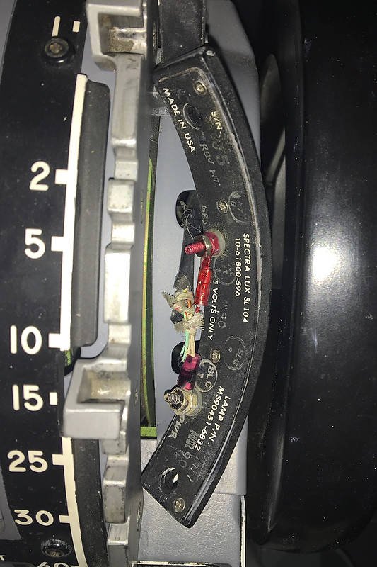
Power requirements for SMART are 5 and 28 Volts. The former is for the backlighting of the Flaps gauge, while 28 Volts is required for the illumination of the various annunciators in the Master Caution System (MCS) and AFDS units.
The power supply for the 28 volts is standalone and resides in the Power Supply Rack (PSR), while the 5 and 12 volt power is internally generated through the use of a 5 and 12 volt step down controller.
The step down modules are mounted within the SMART module. The benefit of using step down modules is two-fold. It limits the number of wires connected with outside power supplies, whilst taking full advantage of using only one external 28 volt power supply.
28 volt busbar, internal temperature probe (SMART probe) and grey-coloured 400 hertz unit
The components that are installed within the module, for the most part, do not generate heat, however, the 400 hertz inverter unit does generate considerable heat (1).
To facilitate cooling, if and when required, two 12 volt brushless fans have been installed either side of the inverter in the side walls of the module. An internal temperature probe (SMART probe) will, dependent upon the generated internal ambient temperature (currently 88F), automatically turn the fans on or off. This is accomplished by the use of a relay.
Advanced Features - Why SMART is called SMART
400 hertz calibration toggle and LED. When placed to CALIB the system receives constant 400 hertz and the LED will flicker several colours
OEM gauges, for the most part, require 400 hertz to operate correctly. This is especially so for any gauge that has a movement needle or dial (such as gauges located in the forward overhead).
An advantage of using an aircraft inverter, is that the 400 hertz power the inverter generates, is more than enough to operate more than one gauge. Therefore, to harness this power for additional OEM gauges (such as in the overhead panel), SMART has been installed with an accessory plug to distribute 400 Hertz to other connected gauges.
Pull/Throw Toggles (accessory gauges and calibration)
If you look carefully at the picture of the SMART module, you will note four pull/throw toggles mounted along the sides of the module. The toggles are used to facilitate the following:
Toggle 1: This toggle, when selected from NORM to AUX enables an additional 28 volt power supply to be connected to the module. This may be necessary if additional gauges, that use 400 hertz, require direct power.
Toggle 2: This toggle, when selected from NORM to AUX enables 400 hertz to travel to the plug located in the firewall of the module. The plug facilitates the connection of additional OEM gauges that utilise 400 hertz. The toggle operates in unison with the red-coloured button mentioned earlier in this artickle. The toggle must be selected to AUX and the red coloured button depressed to enable the distribution of 400 hertz outside of the module..
Toggle 3: Toggle 3 is used during the initial calibration of the flaps gauge. This toggle when moved from NORM to ADV facilitates manual calibration of the two pointer needles, so they align above each other and move as one pointer. ADV is also selected to energise asymmetric flaps operation (currently not implemented in ProSim737 avionics suite).
Toggle 4: Toggle 4 is labelled NORM/CALIB. When calibration is selected, the inverter will constantly generate 400 hertz. A Constant 400 hertz is required at anytime the flap gauge is being calibrated. This toggle also triggers an LED, which shows a flashing multi-coloured light. The LED serves to indicate that the unit is generating 400 hertz and/or is in calibration mode.
(NORM = normal, CALIB = calibration, AUX = auxiliary, ADV= advanced).
Flaps Calibration and Coupling Mechanism (FCCM)
The two flaps calibration coupling mechanisms are used solely to calibrate the flaps gauge. Two hex keys are used to unlock the coupling of the FCCM. This enables the shaft of the FCCM to be manually rotated; thereby, aligning the left and right pointers with each other in the flaps gauge.
OEM flaps gauge. The left and right needles or pointers, used during asymmetric operations, are clearly evident. For normal operation, the two needles are aligned and move as if one needle
Asymmetric Flaps
Asymmetric flaps is probably not a function that many individuals will want to simulate, with the exception of those intending to to simulate aircraft system failures.
ProSim737 does not currently simulate asymmetric flap operation, however, SMART is ready if this function is implemented.
When asymmetrical flaps is implemented, for correct operation the toggle in SMART must be selected to ADV.
Further information concerning the flaps gauge, mechanism and operation will be documented in an additional article and a link added to this page.
Additional photographs of the SMART module can be seen in the Picture Gallery.
Glossary
FCCM – Flaps Calibration and Coupling Mechanism (used to manually calibrate the two flap pointers when 400 hertz is applied).
MCS – Master Caution System (encompasses the fire bell, master warning and system annunciators aka six packs).
OEM – Original Equipment Manufacture. OEM components are real Boeing 737 components that for whatever reason have been discarded from service.
Foot Note
(1:) The amount of heat generated by the FCCM and the 400 hertz inverter unit is reflected by the length of time that the unit is engaged. The inverter is energised only when the flaps are being moved or are in the extended position. When the flaps are retracted and flaps movement ceases, a relay is activated that turns the inverter unit off.
Updated 03 February 2024.


