THROTTLE INTERFACE MODULE (TIM)
The Throttle Interface Module (TIM) provides a platform to house the various interface cards used to operate the OEM throttle quadrant and control the throttle automation. In comparison to the other interface modules, TIM is more complex because of it controls the functionality of the throttle quadrant. Additionally, the module incorporates amperage and voltage meters, a Hobbs meter, and a system of LED lights, that form part of the Interface Alert System. The Hobbs meters is used to measure the number of hours that power has been applied to the interface cards.
This article will mainly discuss the Throttle Interface Module (TIM); however, the module has a close relationship with the Interface Alert System (IAS).
Interface Cards and Functionality
TIM, in addition to housing one 5-Volt and two 12-Volt power supplies accommodates the following interface cards:
Polulu JRK cards (2) – Autothrottle (previously alpha quadrant cards)
Leo Bodnar 836 Joystick Controller card – Movement of levers & buttons
High speed Belkin hub – Only one USB cable to computer
12-Volt power supplies (2) – Power for various throttle systems and autothrottle
5-Volt power supply – Power for Belkin USB hub
Phidget 0/0/8 Interface Kit card – Controls stab trim speeds (forward, aft, flaps in/out, CMD A/B)
Phidget 1066 Advanced Servo Controller card - Controls stab trim indicator movement on throttle
Speed Controller cards (3) – Controls variable speed (4 speeds) of trim wheels
Relays (5) – Controls on/off for stab trim variable speed and specific autopilot
Busbars – As required
Throttle Interface Module (TIM). The three coloured 'traffic lights' can be observed, as can the two series of LEDS, in-between the main cooling fans, that form part of the Interface Alert System (IAS) and the Power Management Buttons (PMBS)
Construction
The module is constructed form heavy duty ABS plastic that has been plastic welded to ensure strength and longevity. The upper lid is hinged to allow easy access to the inside of the module and if necessary the lid can be secured by tightening six thumb screws.
Because TIM has three power supplies mounted in the module, the internal space can become warm with extended use, especially if ambient temperatures are high. To counter this and to improve cross-through ventilation, there are four 5 cm sized diameter holes (mouse holes) either side of the module and six fans; two primary fans and four smaller secondary fans.
The two high-capacity fans are located immediately above the power supply units and operate whenever TIM is working The four secondary fans have been strategically located at each quadrant of the module and operate on demand. Two of the fans rotate in a clockwise direction while the other two fans rotate counter clockwise; thereby, increasing the movement of air through the module. The fans have been wired in parallel and Inside the module there are two toggle switches that enable each pair of secondary fans to be turned on or off as required.
To stop any foreign body (or cockroaches) from entering the module, the ‘mouse holes’ have been protected by low-grade wire mesh that is attached to the ABS plastic.
White Space, Platforms and Ferrules
One of the problems associated with the trial Interface Master Module (IMM), now discarded, was that there was minimal space to enable work to be done in and around the interface cards and wiring. To counter this drawback, TIM is considerably larger in size than its predecessor. The extra size ensures there is sufficient ‘white space’ to troubleshoot any possible wiring problems. Furthermore, all the wires within TIM are colour-coded and labelled to avoid confusion.
To facilitate easier removal of any interface card, the cards have been mounted directly onto 1 cm ABS plastic platforms which are 1 cm in height; the platforms (called ‘oil rigs’) are mounted directly to the floor of the module. The use of a platform to secure the card minimises the possibility of damaging the floor of the module when the card is removed. It also provides additional depth with which to manipulate wires to and from the card. To facilitate easy removal of any wires from an interface card, all wires have been crimped using ferrules. Ferrules make it very easy to remove a wire from a terminal, with the added advantage of appearing very neat.
Cables and Connection
Five colour-coded straight-through cables connect from TIM to the Throttle Communication Module
Dedicated VGA and serial port cables (straight-through cables) have been used to enable TIM to be connected with the throttle quadrant. The use of a dedicated cable minimises the number of loose wires that connect to the throttle quadrant and other OEM components.
Each cable mates with a dedicated D-Sub connection that incorporates tightening screws. Once a straight-through cable is attached and secured to the module firewall, there is no chance that the cable will work its way loose causing an intermittent connection.
The use of straight-through cables means the numerous wires are relatively neat, and most importantly manageable.
Belkin usb hub nestling between two 12-Volt power supplies. The 5-Volt power supply is located beneath the usb hub. . Note the ferrite choke on the main USB cable that connects to the server computer, and use of short USB cables
The five straight-through cables connect to the Throttle Communication Module (TCM). The TCM is a small ABS constructed box that is mounted directly to the forward bulkhead of the throttle quadrant. The TCM, which accommodates various 12-volt busbars, is the interface between the TIM and the throttle quadrant.
My philosophy is to minimise the number of USB cables that connect with the computer. To facilitate this a high quality 5-volt powered Belkin hub has been installed inside TIM. The various interface cards connect directly to this powered hub via short USB cables. A single USB cable leaves TIM to be connected with the server computer. To avoid the possibility of electromagnetic interference (EMI) this cable is fitted with a ferrite choke.
Sectors, Power Management Buttons and Oddities
TIM has been designed from outset into three sectors. They are a:
5-volt sector (red LED);
12-volt sector (green LED); and.
An automation sector (blue LED)
rear of tim showing traffic lights and interface alert system (IAS)
Each sector can be turned on or off as required by depressing an illuminated colour-coded LED button located on the rear of TIM. Due to the lights resemblance to traffic lights (red, green and blue), these buttons have been called 'traffic lights'.
Depressing the red traffic light will turn on the 5 Volt sector which will power the Belkin hub and the various ancillary displays (discussed later). The green traffic light will engage the 12 Volt sector to operate the power supplies and relays, and the blue traffic light will engage the throttle quadrant automation (movement of thrust levers).
Taking the throttle automation offline can be helpful when troubleshooting problems.
The 12-Volt sector provides the power for the following:
Speedbrake deployment;
Stab trim wheel motor and logic;
12-Volt busbar (located in Throttle Communication Module);
12-Volt busbar (located in Throttle Interface Module);
Cooling fans; and,
The parking brake actuator.
For additional information - Interface Alert System and Power Management Buttons.
TIM with lid raised. The raised 'oil rig' platforms can be observed as can the colour-coded D-Sub connectors. The green button (not illuminated) enables the power to the trim wheels to be cut-off, allowing quiet flight
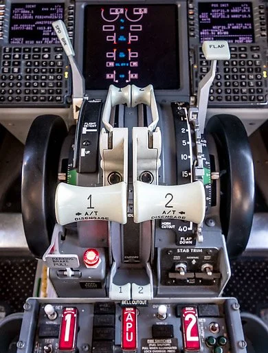
An oddity is a single green push-in LED light located on the opposite side of the module, directly below the straight-through cables and their D-sub connectors. If this button is released (light extinguished) the power to the trim wheels is disengaged (relay on/off). This functionality, although unrealistic, allows the trim wheel to be silenced so that family members are not disturbed, when flying at night, by the noisy rotation of the trim wheels.
Accessory Displays
Located on the upper lid of TIM are a number of ancillary displays. These include a Hobbs meter, a digital clock, and four voltage/amperage gauges. The Hobbs records the amount of time that the module has had power connected to it, while the other four displays monitor 5 and 12-Volt amperage draw. A digital clock completes the ancillary displays.
Power Requirements
tim Ancillary displays: Hobbs meter, amperage and voltage displays
TIM requires 5 and 12 volts to operate. TIM is not connected to the Power Supply Rack (PSR) as I wanted the system to be completely standalone.
As such, the module contains two standard 12-Volt power supplies. One supply is dedicated to provide power to the autothrottle motors while the second 12-Volt unit provides power for other throttle components, such as the movement of the speedbrake, stab trim wheels and trim tabs, parking brake light, cooling fans, LEDS, ancillary voltage and amperage displays, and the parking brake actuator. The 5-Volt power supply is a small 'mini' supply which is dedicated to powering the Belkin hub.
Location of TIM
The module, along with other modules, sits on a small three-shelf bench located forward of the Main Instrument Panel (MIP) on the First Officer side. The bench is large enough to store several interface modules and can be easily accessed.
Additional photographs can be found in the Picture Gallery.
Updated 03 February