Fabricating a String Potentiometer
/Bespoke string potentiometer
String potentiometers are fast becoming the mainstay for those wanting to obtain accurate outputs when a lever is moved, such as the: ailerons, elevators, rudder, flaps, speedbrake, or thrust levers in the throttle quadrant. This is because the slightest movement of a the string is registered by the potentiometer.
While commercial made string potentiometers can be purchased, they are not inexpensive, and if used will deliver an order of accuracy that isn’t necessary for the assigned tasks.
In the example discussed I I am not using a commercial string potentiometer. Rather, a standard Bourne 3500-3501 rotary potentiometer has been adapted to use a string.
Requirements
You will need the following items:
Bourne rotary potentiometer;
Plastic housing box;
6 screws (to secure box lid and to fasten spool);
One nut and washer (to secure potentiometer to box)
A retractable spring-loaded spool and stainless steel ot nylon string;
A cylindrical piece if moulded ABS plastic (or wood); and,
A small dog leash type clip or other fastening device (not pictured).
It’s best to use a CNC machine to fabricate the correctly shaped box, however, any box can be used. Boxes can be purchased from electronic shops that are used as a housing for interface cards. These are suitable.
It’s difficult to document exactly how the process is done, but by carefully studying the pictures, you should be able to replicate the process.
Fabrication
Make a small hole in the side of the box for the string. Ensure the hole enables the string to have some lateral movement. You may need to attach some type of protection to the inside or outside of the hole so that the string doesn’t rub the plastic. I have used a soft piece of plastic for this task (Figure 1). Equally suitable is piece of cork (wine bottle)
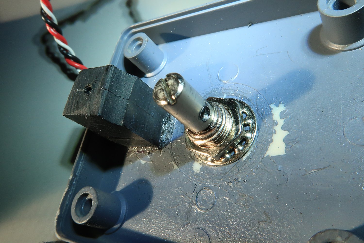
Drill a circular hole in the top of the box to enable the shaft from the potentiometer to be inserted. Secure the shaft with a nut and washer (Figure 2). The main body of the potentiometer will be outside the box.
Glue a piece of solid ABS plastic (or wood) to the lid of the box. Make a small drill hole that enables a screw to be attached. This screw is used to help secure the retractable spool (Figure 2, 4 & 6).
You must fabricate, from a piece of ABS plastic or similar, a cylindrical attachment that is glued to the retractable spring-loaded spool. This piece if plastic must a hole drilled that is the same circumference as the shard of the potentiometer (Figure 3).
The retractable spring-loaded spool is glued to the bottom of the box in direct line with the shaft of the potentiometer. The shaft must align with the hole in the spool (Figure 1).
Drill a small hole into the side of the shaft of the potentiometer and the retractable spool. The hole should be large enough to enable a small screw to secure the retractable spring-loaded spool to the shaft. This is done to stop the spool from freely spooling. When it’s secured, the string when pulled in or out will turn the shaft of the potentiometer (Figure 2, 3 & 6).
When everything is complete, the string should move the shaft of the potentiometer as it is pulled out of the retractable spring-loaded spool. To secure the spring to the control device, a small clip can be used which is attached to the end of the string. I have used a small dog leash style clip, but any clip will work.
Photographs
The fabrication as seen in the gallery photographs appear quite rough. This is because the example photographed was a prototype. If you are carefully, work methodically, and have an eye for detail, then there is no reason why the end product will not look semi-professional.
Additional information: String potentiometers: Are They Worthwhile.