Navigraph Charts Cloud and Charts Desktop - Review

The traditional leather-bound binder that contains hundreds of Jeppesen charts.  This particular binder belonged to Gene Mac Farland, a Captain who flew for 30 years with Continental Airlines

One aspect of simulation which is identical to the real thing is the use of charts.  Whether a professional real-world pilot approaching Heathrow International or a virtual pilot, the correct approach chart will need to be consulted, interpreted correctly, and followed if a safe landing is to be assured.

Not so long ago, Jeppesen Charts provided the mainstay for all professional navigation charts and these thin paper charts were carried in a brown leather binder.  Pilots carried a number of binders with them to allow access to the appropriate chart where necessary.  It was the responsibility of the pilot to ensure that the contents were up-to-date and reflected the latest chart; a tedious task.

Later years have witnessed the introduction of computers and several companies, including Jeppesen, have provide electronic charts that can be viewed using laptops, smart phones and apple i-pads.  The days of  lugging binders is now over, and a binder such the one depicted in the above photograph have become, for the most part, keepsakes and door stops.

Collecting Charts

Virtual pilots have a tendency to ‘collect’ charts from innumerable locations.  The collection can become quite large, and often it is difficult to collate the charts in such a way that it is easy to find the wanted chart, let alone know whether the chart is the most accurate up-to-date version.  

Navigraph

Serious simulator enthusiasts have probably heard of the European-based company Navigraph.  For several years the company has been responsible for the production and distribution of AIRAC cycles that are used to update the Flight Management System (FMS) to maintain the accuracy of the navigation database.

AIRAC Cycles

AIRAC is an acronym for Aeronautical Information Regulation And Control.  An AIRAC cycle contains the current aviation regulations, procedures, and charts for airport, runway, airspace, Instrument Approach Procedures (IAP), Standard Terminal Arrival Routes (STAR), and Standard Instrument Departures (SID).  The AIRAC cycle updates the database used by the aircraft's FMC/CDU.

Without this up-to-date data it is not possible to program the FMC/CDU with any degree of accuracy. 

Navigraph provide a subscription service to AIRAC cycles which are updated several times a year (usually there are thirteen cycles per year)

Charts Database

Navigraph, in addition to supplying regular updated AIRAC cycles, has implemented three additional products:  airport charts, video tutorials and en-route charts.  These products are available via an annual subscription from a data cloud database and/or desktop program.


Area of coverage of Navigraph charts (image courtesy of Navigraph).  This link provides an up-to-date coverage area for Navigraph charts


Airport charts include up-to-date charts for approximately 13,000 airports worldwide. Chart information includes at a minimum: runway data, instrument approach procedures, standard terminal arrival routes and standard instrument departures.  To date, there are approximately 40,000 charts and the number is regularly being expanded with quarterly updates.

Furthermore, several dozen video tutorials instructing in the correct interpretation and use of approach charts are available in addition to dozens of en-route charts which include upper and lower airways.  

The information depicted on the charts originates from suppliers of real-world aviation charts (Navtech) and depicts the latest data, in a format that has been designed by human factor research to be user friendly.

Unlike other companies that have attempted to provide charts for virtual pilots (for example, sim charts), Navigraph charts have been vector scanned in high resolution providing a dataset that can be easily enlarged as required, read, and if required printed in high definition.  Additionally, the information is in colour.  

Ease of Access - Key Feature

In a nutshell, Navigraph has allowed a virtual pilot access to information that otherwise would require considerable collating, revision, and pose difficulties concerning easy access when required. The datasets can be immediately assessed on demand either from a data cloud (charts cloud) or via a desktop program (charts desktop).  

Granted there are many on-line resources to find, read and print approach charts - some better than others.  However, the Navigraph search functionality allows the right chart to be found, quickly and easily, at the appropriate time.  In my opinion, this promotes Navigraph over others programs and on-line resources.

Screen capture of charts cloud showing list of available charts for Hobart, Tasmania, Australia.  The chart can be viewed full screen and can be enlarged as required.  Note this screen capture is of a very reduced quality

Charts Cloud

The cloud provides an easy to use on-line interface, with an effective search functionality that can be accessed using different platforms, including portable devices such as i-pads and smart phones.  To allow speedier future access, charts can be placed in a favourites list or listed in a paper clip (a separate folder) that is linked to your account.  The charts cloud does not allow printing or permanent downloading of a chart and charts are only available when on-line.  Access to the data sets ceases after the annual subscription has expired.

The speed at which charts cloud database can be accessed relates to the Internet connection being used; however, for the most part the server Navigraph uses provides consistent access that should be suitable for most users, with the exception of those that use dial-up.

Navigraph Charts 4 desktop opening screen

Charts Desktop

The charts desktop is a program supplied by Navigraph (free of charge), which resides on your computer and allows charts to be downloaded for access when off-line.  This has the obvious benefit of faster access times if the Internet connection is less than optimal.

The program has the capability to list charts as favourites for easy and fast access, in addition to having a highly responsive search engine.  Unlike the charts cloud, the charts desktop allows access to any chart that has been downloaded after the annual subscription has expired; however, after the subscription has expired the charts cannot be updated.  Another benefit in using the program is that charts can be printed.

Updates

Navigraph regularly updates the database with additional charts and changes to pre existing charts.  The program advises you of an update when you mouse over the chart name.  The program will then allow you to maintain the existing chart or download and replace the chart with the newer version.   Updates are usually half a dozen times a year

Is it a Worthwhile Investment ?

Whether Navigraph chart data is of benefit to you will depend upon how many different airports you fly from and to, how often you fly, and how much money you are prepared to shell out for the convenience and ease of accessed chart information.  Certainly, it is far easier to maintain a collection of charts electronically than store several binders of paper!

A subscription (using the charts cloud or desktop program) is currently 47.92 Euro excluding VAT.  This price allows unlimited access to all charts, and includes the ability to view all instructional videos, which have been professionally produced and run each for approximately 8 minutes duration.  Short of a subscription, individual charts and videos can be purchased separately for a once off fee.  In contrast to purchasing the Jeppesen electronic charts from Jeppesen or an ongoing seller, this fee is reasonable.

Short Review

I elected to not write an in-depth review of Navigraph and their products as the Navigraph interface and their products are constantly being upgraded.  A review may soon be out-of-date!  This review has dealt primarily with the airport charts and has not examined in details the en-route charts or training videos that come packaged with a charts cloud subscription.

Navigraph’s website is very comprehensive and includes several images of their charts that depict the high quality of their product, along with examples of the various programs and how they operate. 

Whilst the charts are not 100% identical to Jeppesen real-world counterparts (various information has been merged and interpolated), the detailed datasets, consistent high quality, and ease of searching and accessibility, make the administrative aspect of virtual flying more enjoyable.

Disclosure

The content in this post is not meant to directly promote or endorse Navigraph.  To trial this software, I purchased a subscription to the charts cloud and charts desktop.  To date, I have been very pleased with the quality of the Navigraph charts and will probably continue to supplement my real-world paper charts with information from this source.

UPDATE: There have been massive changes and improvements to Navigraph since this article was published. A more up-to-date review will be written at some stage. Navigate to the Navigraph website.

B737-600 NG Fire Suppression Panel (Fire Handles) - Evolutionary Conversion Design

737-600 Next Generation Fire Suppression Panel installed to center pedestal.  The lights test illuminates the annunciators

737-600 NG Fire Suppression Panel light plate showing installed Phidget and Phidgets relay card

Originally used in a United Airlines 737-600 Next Generation aircraft and purchased from a wrecking yard, the Fire Suppression Panel has been converted to use with ProSim737 avionic suite. The panel has full functionality replicating the logic in the real aircraft.

This is the third fire panel I have owned.  The first was from a Boeing 737-300  which was converted in a rudimentary way to operate with very limited functionality - it was backlit and the fire handles lit up when they were pulled. The second unit was from a 737-600; the conversion was an intermediate design with the relays and interface card located outside the unit within the now defunct Interface Master Module (IMM).  Both these panels were sold and replaced with the current 600 Next Generation panel. This panel is standalone, which means that the Phidget and relay card are mounted within the panel, and the connection is via the Canon plugs and one USB cable.

I am not going to document the functions and conditions of use for the fire panel as this has been documented very well in other literature.  For an excellent review, read the Fire Protection Systems Summary published by Smart Cockpit.

Nomenclature

Before going further, it should be noted that the Fire Suppression Panel is known by a number of names:  fire protection panel, fire control panel and fire handles are some of the more common names used to describe the unit.

Panel with outer casing removed showing installation of Phidget and relays.  Ferrules are used for easier connection of wires to the Phidget card.  Green tape has been applied to the red lenses to protect them whilst work is in progress

Plug and Fly Conversion

What makes this panel different from the previously converted 737-600 panel is the method of conversion.  

Rear of panel showing integration of OEM Canon plugs to supply power to the unit (5 and 28 volts).  The USB cable (not shown) connects above the middle Canon plu

Rather than rewire the internals of the unit and connect to interface cards mounted outside of the unit, it was decided to remove the electronic boards from the panel and install the appropriate interface card and relays inside the unit.  To provide 5 and 28 volt power to illuminate the annunciators and backlighting, the unit uses the original Canon plugs to connect to the power supplies (via the correct pin-outs).  Connection of the unit to the computer is by a single USB cable.  The end product is, excusing the pun - plug and fly.

Miniaturization has advantages and the release of a smaller Phidget 0/16/16 interface card allowed this card to be installed inside the unit alongside three standard relay cards.  The relays are needed to activate the on/off function that enables the fire handles to be pulled and turned.

The benefit of having the interface card and relays installed inside the panel rather than outside cannot be underestimated.  As any serious cockpit builder will attend, a full simulator carries with it the liability of many wires running behind panels and walls to power the simulator and provide functionality. Minimising the number of wires can only make the simulator building process easier and more neater, and converting the fire handles in this manner has followed through with this philosophy.

Complete Functionality including Push To Test

The functionality of the unit is only as good as the flight avionics suite it is configured to operate with, and complete functionality has been enabled using the ProSim737 avionics suite. 

One of the positives when using an OEM Fire Suppression Panel is the ability to use the push to test function for each annunciator.  Depressing any of the annunciators will test the functionality and cause the 28 volt bulb to illuminate.  This is in addition to using the lights test toggle located on the Main Instrument Panel (MIP) which illuminates all annunciators simultaneously.

At the end of this post is a short video demonstrating several functions of the fire panel.

The conversion of this panel was not done by myself.  Rather, it was converted by a gentleman who is debating converting OEM  fire panels and selling these units commercially; as such, I will not document how the conversion was accomplished as this would provide an unfair disadvantage to the person concerned.

Differences - OEM verses Reproduction

There are several reproduction fire suppression panels currently available, and those manufactured by Flight Deck Solutions and CP Flight (Fly Engravity) are very good; however, pale in comparison to an OEM panel.  Certainly, purchasing a panel that works out of the box has its benefits; however the purchase cost of a reproduction panel is only marginally less that using a converted OEM panel.

By far the most important difference between an OEM panel and a reproduction unit is build quality.  An OEM panel is exceptionally robust, the annunciators illuminate to the correct light intensity with the correct colour balance, and the tension when pulling and turning the handles is correct with longevity assured.  I have read of a number of users of reproduction units that have broken the handles from overzealous use; this is almost impossible to do when using a real panel.  Furthermore, there are differences between reproduction annunciators and OEM annunciators, the most obvious difference being the individual push to test functionality of the OEM units.

737-300 Fire Suppression Panel. Note the different location of korrys

Classic verses Next Generation Panels

Fire Suppression Panels are not difficult to find; a search of e-bay usually reveals a few units for sale.  However, many of the units for sale are the older panels used in the 737 classic aircraft. 

Although the functionality between the older and newer units is almost identical, the similarity ends there.  The Next Generation panels have a different light plate and include additional annunciators configured in a different layout to the older classic units.

737-300 Fire Suppression Panel. this panel is slightly different to the above panel as it has extra korrys for more advanced fire logic

One of the reasons that Next Generation panels are relatively uncommon is that, unless unserviceable, the panels when removed from an aircraft are sold on and installed into another aircraft.

Video

The video demonstrates the following:

  • Backlighting off to on (barely seen due to daylight video-shooting conditions)

  • Push To Test from the MIP (lights test)

  • Push To Test for individual annunciators

  • Fault and overhead fire test

  • Switch tests; and,

  • A basic scenario with an engine 1 fire.

NOTE:  The video demonstrates one of two possible methods of deactivating the fire bell.  The usual method is for the flight crew to disable the bell warning by depressing the Fire Warning Cut-out annunciator located beside the six packs (part of the Master Caution System) on the Main Instrument Panel (MIP).  An alternative method is to depress the bell cut-out bar located on the Fire Suppression Panel. 


737-600 Fire Suppression Panel


Boeing Chart (Map) Lights - B737NG and Classic B737 Types

Chart lights removed from a Boeing 737-800 NG airframe.  Colour, appearance and design is different to the older style lights used in the classic airframes

Chart lights (also called map lights) are attached adjacent to the overhead panel and are used to illuminate, in particular, the chart holders attached to the yoke during night time operations. There are two lights, one on the Captain-side and the other on the First Officer-side.

The light from the unit can be focused from a wide angle to a narrow beam by twisting the focus ring at the front of the light.  Each light can also be swivelled and moved vertically to position the light beam in a particular place on the flight deck (for example, chart plates).

The switches (knobs) that turn the light on and off are located on the sidewalls of the Captain and First Officer side of the flight deck.  The light can be dimmed if necessary by rotating the knob.

The chart lights are mounted near each the eyebrow windows.

Chart light removed from a Boeing 737-400 airframe.  The light has a differing focus ring, appearance and colour to the NG style (click to enlarge).  I believe this style of chart light is also used on the B747 aircraft

Two Styles (Classic and NG)

To my knowledge, there are two styles of chart light that have been used in the Boeing 737. The fatter style used in the classic series airframes and the more slender style used in the Next Generation airframes.  I have little doubt that there may also be small differences between light manufacturers.

The main aesthetic difference between the older 737 classic airframe chart lights and the newer Next Generation style is that the older lights are squatter and a little fatter in shape; the Next Generation is longer, more slender-looking and has a smaller footprint.

Chart light showing reflector dish on inner side of end cap.  This style is the older light type used in the 737 classic airframes

Other differences are internal and relate to how the light is focused on the lens and the physical shape of the focus rung used to alter the angle of light coverage.

Ingenious Design

Both style lights have an ingenious design to allow the light to be focused.   Removing the rear plate of from the older style light reveals the inner side to be a circular reflector dish (see image) which evenly distributes the throw of light when the unit is set to wide angle. 

The newer Next Generation style lights use an aperture blade which either enlarges or contracts as the focus ring is turned.  This design is identical to how a camera aperture works.

Both styles can use either a 12 or 28 Volt bulb; the later will generate a brighter light.  Connection is direct to the power supply (12 or 28 Volt).  An interface card is not required.

The NG style chart light.  A blade aperture controls the amount of light that is reflected onto the thick lens glass

Original Equipment Manufacturer (OEM)

Put bluntly, you cannot achieve a more realistic end product than when using a real aviation part.  Genuine parts, although at times difficult to find, are built to last; if they can withstand the continue abuse of pilots in a flight deck then they are more than adequate for home simulation use. 

It's true that while some parts appear used with faded and missing paint, they can easily be cleaned up with a fresh coat of paint.  Personally, I prefer the worn-appearance.

Advertise With Me - Thank You, But No Thanks....

When I began this website, I had little insight that the site would be as regularly visited as it is; last month the site received 152,555 visits from different ISP addresses not including robots & spiders.

Can We Advertise With You....

Two companies that produce flight simulation merchandise have contacted me asking that I write about their products and actively support heir products on this website.  In return for my favourable response, the company will give me free products and a percentage of any sales that are generated from my website.

'Money is money' and everyone can probably always use a little more.  The funds generated will probably cover the annual cost of hosting this site and leave a little left over to pay the power bill…

I have thought about the offer; however, have decided to not support or promote any company for the sake of profit… 

Flaps 2 Approach was developed to document the building progress of a Boeing 737-800 simulator, and evolved to include technical and theoretical information. If I commercialise this website, the unbiased nature of the site will be compromised and the site will become another 'megahorn' promoting 'coloured beads and trinkets'.  To alter the style, flare and direction of the site from essentially what is a hobby-based website to that of market-orientated site, does not sit favourably with me; therefore, the website will continue along the same footing.

I believe it’s important not to be swayed by business (and money) and to continue to tell it as it is, or at least how I see it…

I dislike Advertising Pop-Ups....

I dislike the blanket-style of unwanted advertising that many websites have, whether it is generated by google or as adverts for products from particular companies, and  I certainly do not want to add to this advertising glut.

I hope you agree with this philosophy and continue to enjoy the website and its content.   'Blue Skys',   

B737-800 NG Flight Mode Annunciator (FMA)

oem Flight Mode annunciator (737-800)

Automatic Flight System - Background

The Boeing 737-80 has a relatively sophisticated Automatic Flight System (AFS) consisting of the Autopilot Flight Director System (AFDS) and the Autothrottle (A/T).  


The Boeing 737-800 NG has a relatively sophisticated Automatic Flight System (AFS) consisting of the Autopilot Flight Director System (AFDS) and the Autothrottle (A/T).   The system is as follows:

  • The N1 target speeds and limits are defined by the Flight Management Computer (FMC) which commands airspeeds used by the A/T and AFDS;

  • The A/T and AFDS are operated from the AFDS Mode Control Panel (MCP), and the FMC from the Control Display Unit (CDU); 

  • The MCP provides coordinated control of the Autopilot (A/P), Flight Director (F/D), A/T and altitude alert functions; and,

  • The Flight Mode Annunciator (FMA), located on the Captain and First Officer side of the Primary Flight Display (PFD),  displays the mode status for the AFS.

If you read through the above slowly and carefully it actually does make sense; however, during in-flight operations it can be quite confusing to determine which system is engaged and controlling the aircraft at any particular time.

Reliance on MCP Annunciations

Without appropriate training, there can be a reliance on the various annunciations and lights displayed on the Mode Control Panel (MCP).  While some annunciations are straightforward and only illuminate when a function is on or off (such as the CMD button), others can be confusing, for example VNAV.

Do not reply on the MCP.  Always refer to the FMA to see what mode is controlling the aircraft.

Flight Mode Annunciator (FMA)

All Boeing aircraft are fitted with an FMA of some type and style.  The FMA on the Next Generation is located on the Captain and First Officer side Primary Flight Display, and is continuously displayed.  The FMA indicates what system is controlling the aircraft and what mode is operational.  All flight crews should observe the FMA to determine operational status of the aircraft and not rely on the annunciators on the MCP that may, or may not indicate a selected function.

The FMA is divided into three columns and two rows. The left column relates to the Autothrottle while the center and right hand column display roll and pitch modes respectively.  The two rows provide space for armed and selected annunciations to be displayed.  Selected modes that are operational are always coloured green while armed modes are coloured white. 

Below the two rows are the Autopilot Status alerts which are in larger green-coloured font, and the Control Wheel Steering (CWS) displays which are coloured yellow.  The Autopilot Status alerts are dependent upon whether a particular system has been installed into that aircraft.  For example, Integrated Approach Navigation (IAN), and various autoland capabilities.

When a change to a mode occurs (either by a flight crew or by the Automatic Flight System), a mode change highlight symbol (green-coloured rectangle) is displayed around the changed mode annunciation.  The rectangle will be displayed for 10 seconds following the change in mode.

Unfortunately, not all avionics suites have the correct timing (10 seconds) and some displays the rectangle for only 2 seconds.  According to the Boeing manual the default time should be 10 seconds.

figure 1: common mode annunciations that the FMA can display.  FMA annunciations may differ between airframes depending upon the software installed to the aircraft (and avionics suite used in your simulation).  G, W and Y indicates the colour of the annunciation (green, white, or yellow). the pitch mode FOR column and CWS display are not populated. 

ERRATUM: ILS, SINGLE CH and IDLE HAVE NOT BEEN INCLUDED WHEN THEY SHOULD HAVE

Important Points:

  • An annunciation that is green-coloured indicates a selected mode.

  • An annunciation that is white-coloured indicates an armed mode.

  • If there is some confusion to what mode is currently flying the aircraft, the FMA should be what you look at - not the MCP.

Video

Boeing 737 ILS CAT IIIa Autoland PFD demonstrating FMA.


B737 Autothrottle (A/T) - Normal and Non-Normal Operations

Mode Control Panel (MCP) showing A/T on/off solenoid switch and speed window.  The MCP shown is the Pro model manufactured by CP Flight in Italy

THIS ARTICLE IS UNDER REVIEW - CHANGES TO FOLLOW.

  • UNTIL UPDATES APPEAR HERE, PLEASE SEE THIS LINK

The Autothrottle (A/T) is part of the Automatic Flight System (AFS) comprising the Autopilot Flight Director System (AFDS) and the autothrottle.  The A/T provides automatic thrust control through all phases of flight. 

The autothrottle functionality is designed to operate in unison with the Autopilot (A/P), Nevertheless, a flight crew will not always adhere to this use, some crews preferring to fly manually or partially select either the autopilot or autothrottle.

A search on aviation forums will uncover a plethora of comments concerning the use of the autothrottle which, combined with autopilot use and non-normal procedures, can be easily be misconstrued.  An interesting discussion can be read on PPRuNe.

This post will examine, in addition to normal A/T operation, some of the non-normal conditions, their advantages and possible drawbacks.  Single engine operation will not be addressed as this is a separate subject.

Additional Information:

Autothrottle (A/T) Use

The autothrottle is engaged whenever the A/T toggle is armed and the speed annunciator is illuminated on the Mode Control Panel (MCP).  Either of these two functions can be selected together or singularly. 

The autothrottle is usually engaged during the takeoff roll by pressing the TO/GA buttons located under the thrust lever handles.  This is done when %N1 stabilises for both engines at around 40%N1.  This will engage the autothrottle in the TO/GA command mode.  The reason the autothrottle is used during takeoff is to simplify thrust procedures during a busy segment of the flight.

FMA Captain-side PFD showing TO/GA annunciated during takeoff roll

Once engaged, the TO/GA command mode will control all thrust outputs to the engines until the mode is exited, either at the designated altitude set on the MCP, or by activating another automaton mode such as Level Change (LVL CHG).  When TO/GA is engaged, the Flight Mode Annunciator (FMA) will announce TO/GA providing a visual cue.

The use of the autothrottle is at the discretion of the pilot flying, however, airline company policy often dictates when the crew can engage and disengage the A/T. 

The Flight Crew Training Manual (FCTM) states:

‘A/T use is recommended during takeoff and climb in either automatic or manual flight, and during all other phases of flight’.

When to Engage / Disengage the Autothrottle

A question commonly asked is: ‘When is the autothrottle disengaged and in what circumstances’  Seemingly, like many aspects of flying the Boeing aircraft, there are several answers depending on who you speak to or what reference you read.

In the FCTM, Boeing recommends the autothrottle be used only when the autopilot is engaged (autopilot and autothrottle coupled).

In general, a flight crew should disengage the autothrottle system at the same time as the autopilot.  This enables complete manual input to the flight controls and follows the method recommended by Boeing.

My preference during an approach is to disconnect the autothrottle and autopilot no later than 1500 feet AGL.  This corresponds to the altitude that the aircraft must be in landing configuration, gear down, flaps 30 and within vertical and lateral navigation constraints with landing checks completed.  Disconnecting the autothrottle and autopilot earlier in the approach provides additional time to transition from automated flight to manual flight, and establish a 'feel' for the aircraft before landing. 

It's not uncommon that  flight crew will manually fly the aircraft, especially 'old school' pilots who are very conversant with hand flying.   I know some crews that will fly from 10,000 feet to landing using the Flight Director (FD), ILS, VNAV and LNAV cues on the Primary Flight Display (PFD) for guidance and the information displayed on the Navigation Display (ND) for situational awareness.  Many pilots enjoy hand-flying the aircraft during the approach phase.

Important Point:

  • Whenever hand flying the aircraft with the autothrottle not engaged, it's very important to monitor the airspeed.  This is especially so during the final approach, when thrust can easily decay to a speed very close to stall speed.

The Autothrottle is Designed to be Coupled with the Autopilot

The autothrottle is a sophisticated automated system that will continually update thrust based on minor pitch and attitude changes, and operates exceptionally well when coupled with the autopilot.  But, when the autopilot is not selected and the autothrottle selected, its reliability can be questionable.

Some crews believe that if a landing is carried out with the autopilot off and the autothrottle engaged, and a fall in airspeed occurs, such as during the flare, then the autothrottle will apply thrust which has the potential to cause a tail strike.  Likewise, if during the approach there are excessive wind gusts, pitch coupling (discussed below) may occur.

The advantages of using the autothrottle and autopilot together (coupled) are:

(i)      Speed is stabilized;

(ii)     Speed floor protection is maintained;

(iii)    Task loading is reduced; and,

(iv)    Flight crews can concentrate on visual manoeuvring and not have to be overly concerned with wind additives

The disadvantages of using the autothrottle with the autopilot not selected are:

(i)     Additional crew workload and possible loss of situational awareness (due to workload);

(ii)    Potential excessive and unexpected throttle movement caused by pitch and attitude changes;

(iii)   Potential excessive airspeed when landing in windy conditions with gusts;

(iv)   The potential for pitch coupling to occur (discussed below); and,

(v)    A loss of thrust awareness (out of the loop).

Important Point:

  • The autopilot and autothrottle should not be used independent of one another.

737 Next Generation thrust levers

Boeing 737 Design

The design  of the 737 airframe is prone to pitch coupling because of its under wing mounted engines.  The engine position causes the thrust vector to pitch up with increasing thrust and pitch down with a reduction in thrust.

The autothrottle is designed to operate in conjunction with the autopilot, to produce a consistent aircraft pitch under normal flight conditions.  If the autopilot is disengaged but the autothrottle remains engaged, pitch coupling may develop.

Pitch Coupling

Pitch coupling is when the autothrottle system actively attempts to maintain thrust based on the pitch/attitude of the aircraft. It occurs when the autopilot is not engaged and manual inputs (pitch and roll) are used to control the aircraft. 

If the pitch inputs are excessive, the autothrottle will advance or retard thrust in an attempt to maintain the selected MCP speed.   This coupling of pitch to thrust can be potentially hazardous when manually flying an approach, and more so in windy conditions.

Scenario - pitch coupling

For example, imagine you are in level flight with autothrottle engaged and the autopilot not engaged, and a brief wind change causes a reduction in airspeed. The autothrottle will slightly advance the throttles to maintain commanded speed. This in turn will cause the aircraft to pitch slightly upwards, triggering the autothrottle to respond to the subsequent speed loss by increasing thrust, resulting in further upward pitch. The pilot will then correct this by pushing forward on the control column to decease pitch. As airspeed increases, the autothrottle will decrease thrust causing the aircraft to decrease more in pitch.

The outcome is that a coupling between pitch and thrust will occur causing a roll-a-coaster type ride as the aircraft increases and then decreases pitch, based on pilot input and autothrottle thrust control.

A/T ARM solenoid, N1 and speed button.  The N1 and speed button illuminate when either is in active mode.  In the image, the A/T is armed; however, the speed option is not selected (the annunciator is extinguished).  This enables thrust to be controlled manually

Autothrottle Non-Normal Operations (Arm Mode)

The primary function that the A/T ARM mode is to provide minimum speed protection.  A crew can ARM the throttle but not have it linked to a speed.  To configure the autothrottle in ARM mode, the  A/T toggle solenoid on the MCP is set to ARM, but the SPEED button is not selected (the annunciator is not illuminated).

Scenario - speed button not selected during approach

Some flight crews prefer during an approach, to arm the autothrottle, but not have the speed option engaged (speed annunciator extinguished). 

By doing this during a non-precision approach, it enables a Go-Around to be executed more expediently and with less workload  (the pilot flying only has to push the TO/GA buttons on the thrust lever and the autothrottle will engage).

If the approach proceeds smoothly and a Go-Around is not required, the crew will prior to landing, disengage the A/T solenoid switch on the MCP by either manually 'throwing' the toggle or pressing the A/T buttons located on the thrust levers.  Although favoured by some flight crews, this practice is not authorized by all airlines, with some company policies expressly forbidding the ARM A/T technique.

The recommendation by Boeing in the B737 Flight Crew Training Manual (FCTM) states:

‘The A/T ARM mode is not normally recommended because its function can be confusing. The primary feature the A/T ARM mode provides is minimum speed protection in the event the airplane slows to minimum maneuvering speed. Other features normally associated with the A/T, such as gust protection, are not provided’.  (When the A/T is armed and the speed button option not selected).

Autothrottle Speed Protection and Vref in Windy, Gusty and Turbulent Conditions

To provide sufficient wind and gust protection, when using the autothrottle during an approach in windy conditions, the command speed should set to the correct wind additive based on wind speed, direction and gusts (between Vref+5 and Vref +20).  

The use of an additive creates a safety envelope that takes into account potential changes in wind speed and minimises the chance of the autothrottle commanding a speed that falls below Vref.  Remember, that as wind speed varies the autothrottle will command a thrust based on the speed.

During turbulence, the autothrottle will maintain a thrust that is higher than necessary (an average) to maintain command speed (Vref).

Important Points:

  • When the autothrottle is not engaged, or the speed option on the MCP deselected, minimum speed protection is lost.

  • Always add a wind additive to Vref based on wind strength and gusts.  Doing so provides speed protection when the autothrottle is engaged.

Refer to Crosswind Landings Part 2 for additional information on Vref.

A/T disengage button on throttle thrust lever.  This is an OEM throttle from a B737-300 series.  The button is identical to that used in the NG with the exception that the handles are usually white and not grey in colour.  Depressing this button will disengage the autothrottle and disconnect the A/T solenoid switch on the MCP

Manual Override - Engaging the Clutch Assembly

Occasionally, for any number of reasons, the flight crew may need to override the autothrottle. 

The Boeing autothrottle system is fitted with a clutch assembly that enables the flight crew to either advance or retard the thrust levers whilst the autothrottle is engaged.  By moving the thrust levers, the clutch assembly is engaged and the autothrottle goes offline whilst the levers are moved.

The clutch is there to enable the autothrottle to be manually overridden, such as in an emergency or for immediate thrust control.

ProSim737 does not (as at 2018) support manual autothrottle override.

Simulation Nuances

The above information primarily discusses the systems that operate in the real aircraft.  Whether these systems are functional in a simulation, depends on the avionics suite used (Sim Avionics, Project Magenta, etc).

For example, the autothrottle may not maintain the speed selected in the MCP during particular circumstances (for example, turns in high winds). If this occurred in the real world, a crew would manually override the autothrottle.  However, if the avionics suite does not have this functionality, then the next best option is to either:

(i)      Disengage the autothrottle and manually alter thrust; or,

(ii)     Deselect the speed annunciator on the MCP.

Deselecting the speed annunciator will cause the throttle automation to be disengaged; however, the autothrottle will remain in the armed mode.  The second option is a good way to overcome this shortfall of not having manual override.  By deselecting the speed option, the thrust levers can be jiggled forward or aft to adjust the airspeed.  When the speed has been rectified by manual input, the autothrottle can be engaged again by depressing the speed  button.

It's important if the autothrottle is not engaged, or is in the ARM mode, that the crew maintains vigilance on the airspeed of the aircraft.  There have been several incidents in the real world whereby crews have failed to observe airspeed changes.

Manual Flying (no automation engaged)

The benefit of flying with the autothrottle and autopilot not engaged is the ease that the aircraft can be maneuvered.  The crew sets the appropriate %N1 that produces the correct amount of thrust to maintain whatever airspeed is desired; gone are the thrust surges as the autothrottle attempts to maintain airspeed.

Granted, it does take considerable time and patience to become competent at flying manually in a variety of conditions, but the overall enjoyment increases three-fold.

Company Policies

Airline policies often dictate how a flight crew will fly an aircraft, and while some policies are expedient, more often than not they are based on economics (cost savings) for the company in question.

Policies vary concerning autothrottle use.  For example, Ryanair has a policy to disconnect the autothrottle and autopilot simultaneously, as does Kenya Airways.  Air New Zealand and QANTAS have a similar policy, however, define an altitude that disconnection must occur at or before.   If an airline doesn't have a policy, then it's at the discretion of the flight crew who should follow Boeing's recommendation in the FCTM.

Confusion and Second Guessing - Vref with A/T Engaged or Disengaged

There is considerable confusion and second guessing when it comes to determining the Vref to select dependent on whether the autothrottle is engaged or disconnected at landing.  To simplify,

  • If the autothrottle is going to be disconnected before reaching the threshold, the command speed should be adjusted to take into account winds and gusts (as discussed above and refer to Crosswind Landings Part 2).  It's vital to monitor airspeed when the autothrottle is not engaged as during the approach the speed can decay close to stall speed.

  • If the autothrottle is to remain engaged during the landing (as in an autoland precision approach), the command speed should be set to Vref +5.  This provides speed protection by keeping the engine thrust at a level that is commensurate with the Vref command speed.  If wind and gust indicate a higher additive speed, then this should be added to Vref.

Refer to Wind Correction Function (WIND CORR) for information on how to use the Wind Correction function in the CDU.

Final Call

There is little argument that the use of the autothrottle is a major benefit to reduce task loading; however, as with other automated systems, the benefit can come at a cost, which has lead several airlines to introduce company policies prohibiting the use of autothrottle without the use of the autopilot; pitch coupling, excessive vertical speed, and incorrect thrust can lead to hard landings and possible nose wheel collapse, unwanted ground effect, or a crash into terrain.

Ultimately, the decision to use or not use the autothrottle and autopilot as a coupled system is at the discretion of the pilot in command, and depends upon the experience of the crew flying the aircraft, the environmental conditions, and airline company policy.  However,  the recommendation made by Boeing preclude autothrottle use without the autopilot being engaged.

Disclaimer

The content in this post has been proof read for accuracy; however, explaining procedures that are convoluted and often subjective, can be challenging.  Occasionally errors occur. If you observe an error, please contact me so it can be rectified.

Acronyms and Glossary

  • A/P – Autopilot (CMD A CMD B).

  • A/T – Autothrottle.

  • AFDS – Autopilot Flight Director System
.

  • Command Speed - In relation to the Autothrottle, Command Speed is Vref +5 knots.

  • FCTM – Flight Crew Training Manual (Boeing Corporation).

  • FMA – Flight Mode Annunciator.

  • Manual Flight – Full manual flying. A/T and A/P not engaged.

  • MCP – Mode Control Panel.

  • Minimal Speed Protection – Function of the A/T when engaged.  The A/T has a reversion mode which will activate according to the condition causing the reversion (placard limit). (For example, flaps, gear, etc).

  • Pitch Coupling – The coupling of A/T thrust to the pitch of the aircraft.  A/T thrust increases/decreases as aircraft pitch and attitude changes.  Pitch coupling occurs when the A/P is not engaged, but the A/T is enabled.

  • Selected/Designated Speed – The speed that is set in the speed window of the MCP.

  • Take Off/Go Around (TO/GA) – Takeoff Go-around command mode.  This mode is engaged during takeoff roll by depressing one of two buttons beneath the throttle levers.

  • Vref – Landing reference speed.

Updated and Amended 04 July 2019

Primary Flight Display (PFD) - Differences Between Sim Avionics and ProSim737 Avionics Suites

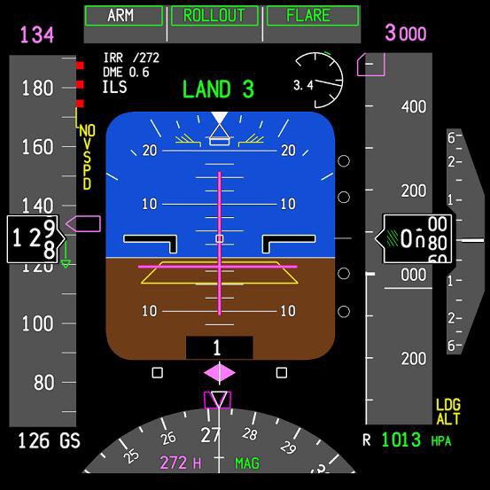
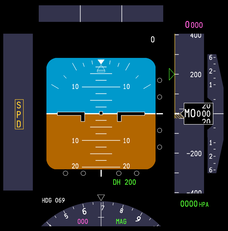
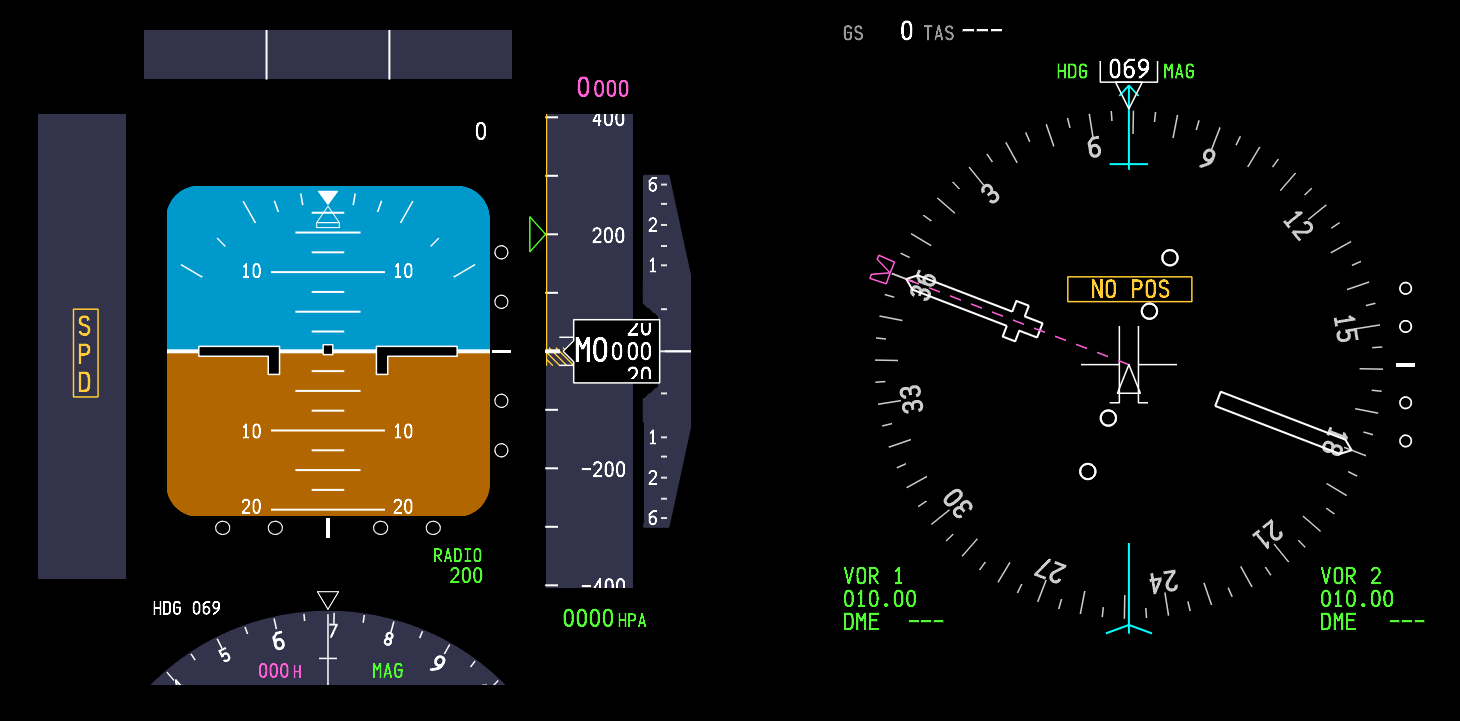
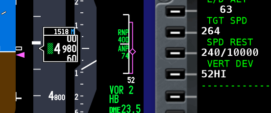
As I work on a slightly more technical article, I thought I would post some images of the Primary Flight Display (PFD) belonging to two of the most popular avionics suites - ProSim737 and Sim Avionics. For reference, I also have also included PFDs used by Aerosoft Australia, Project Magenta and Sismo Soluciones. What is readily apparent is not all suites are identical. Clearly, some developers are using artistic license or do not process the information to be able to replicate the OEM counterpart. Bear in mind when you look at the images, that Sim Avionics and ProSim737 are regularly updated and updates may alter how the PFD is displayed. ProSim737 currently has three releases - Version 1, 2 and 3.

So which PDF accurately reflects the OEM counterpart. It’s a difficult question to answer as the Next Generation encompasses four aircraft types (600, 700, 800 & 900) with each aircraft type using different software and software versions, and this is not discussing company options. Put simply there is subtle variance in how the PFD is displayed.

One aspect that should not be used when comparing suites is the colour; the colour of the PDF can easily be altered by changing the hue in the computer’s display settings.

  • Sim Avionics is owned by Flight Deck Solutions (FDS) in Canada and simulates both the 737 Next Generation and the B777. 

  • ProSim737, developed in the Netherlands, is dedicated solely to the 737 Next Generation.

  • Aerosoft Australia is developed in Australia.

In the interests of disclosure, I own Sim Avionics and ProSim737, but use ProSim737 Version 3.

Important Point:

  • Bear in mind the date of this article (2014). I have no doubt that the display from all avionics suites will change and improve with time becoming closer to the OEM.

A post located on the ProSim737 forum discusses the various PFD differences.  The post can be read here: Comparing the ProSim PFD (thanks Jacob for sending this to me).

BELOW:  Gallery of Primary Flight Displays.

Boeing 737-800 Takeoff Procedure (simplified)

One aspect novice virtual pilots find difficult to grasp is the correct method of flying the aircraft, especially the takeoff, climb and transition to cruise.

The sheer volume of information available on the Internet often results in information overload and it’s understandable that many become bewildered as the boundaries between fact and fiction blur.  Add to this that many articles on the Internet have not been peer reviewed, and you have a recipe set for disaster!

In this article,  I will instruct on the basic procedures used to takeoff, climb, and transition to cruise.  I’ll also provide some insight into how flight crews fly the aircraft, and discuss some of the more important concepts that should be known.

I will not discuss before and after takeoff checklists, the overhead, how to determine aircraft weights, or how to use of the Control Display Unit (CDU).   I will assume all essential elements of pre-flight have been completed.  Also, the following procedures assume both engines are operational.  I will not be addressing engine-out procedures or discussing derates in detail.

Please take note that some procedures are dependent upon what software is used in the Flight Management System (1). Furthermore, the display of specific items, such as the speed reference indicators on the Primary Flight Display (PFD), will only be displayed if the CDU is correctly set-up prior to takeoff.

I have attempted to try and simplify the procedure as much as possible.   However, the automated systems that can be used on the Boeing aircraft are complicated, can be used fully or in part, and can easily generate confusion. Add to this that some procedures are different between an automated and manual takeoff, and some procedures are dictated by airline policy. 

It is a challenge to simplify what in the first place is convoluted and technical.

I have set out the content in three parts:

  • Section One refers to a simplified generic procedure for takeoff (numerical sequence 1–20).  Below each numerical number are important points (summarized as dot points).  Although this section primarily refers to hand flying the aircraft, some automation concepts are discussed.

  • Section Two discusses takeoff procedures using automation.

  • Section Three provides additional information concerning important points mentioned in Section One and Two.

To minimise wordiness in this article, I have for the most part, used acronyms and footnotes.  Refer to the end of the article for a list of acronyms and their meaning.

Peer Review

The information in this article has been peer reviewed by 737 Captain and First Officer.

Automation and Variability

The Boeing 737-800 can be flown with, without, or partly with automation.  The combinations that can be used, how they work, and more importantly when to use them, can fill a book.  Indeed, there is a book (two books) – they’re called the Flight Crew Operations Manual and the Flight Crew Training Manual.

The first point to take on board is that there is no absolute correct method for takeoff and climb.  Certainly, there are specific tasks that need to be completed, however, there is an envelope of variability allowed.  This variability may relate to how a particular flight crew flies the aircraft, environmental considerations (ice, rain, wind, noise abatement, obstacles, etc.), flight training, or a specific airline policy.

Whenever variability is injected into a subject, individuals who think in absolutes - black and white - will have difficulty.  If you are the kind of person who likes to know exactly what to do at a particular time, then I suggest you find a technique that fits with your liking and personality.

SECTION ONE:  Takeoff Guideline (1-20)

The following procedures assume essential elements of pre-flight have been completed (for example, correct set-up of CDU).

1.  Using the Mode Control Panel (MCP), dial into the altitude window an appropriate target altitude, for example 13,000 feet.

2. Command speed is set in the MCP speed window.  The speed is set to V2.  V2 is determined by calculations made by the Flight Management Computer (FMC) based on aircraft weight, environmental conditions and several other parameters.

Important Points:

  • V2 is the minimum takeoff safety speed and provides at least 30° bank capability with takeoff flaps set.  This speed provides a safe envelope to fly with one engine (if an engine failure occurs).

  • You can fly either +15 or +20 knots (maximum +25 knots) above the V2 command speed.  This is done for a number of reasons:  to lower or increase pitch due to the aircraft's weight, or to take into account other environmental variables (this assumes both engines operational), or it is dictated by airline policy.

  • A white-coloured airspeed bug is displayed at V2 +15/20 on the speed tape (part of the PFD). V2+15 knots provides 40° bank capability with takeoff flaps set.   The bug is a visual aid to indicate the correct climb-out speed (bug is discussed later on).  

  • Although not required, it is a good idea is to set the minimums selector to the Acceleration Height as indicated in the CDU.  This will place a green line on the altitude tape of the PFD at the height at which the aircraft’s nose is to be lowered and flap retraction to begin.  This is a visual aid.

3.    Toggle both Flight Director (FD) switches to the O’ position (pilot flying side first).

4.    Set flaps 5 and using the electric trim switch on the yoke, trim the aircraft to the correct trim figure for takeoff. The trim figure is shown on the CDU (for example, 5.5 degrees) and is calculated dependent upon aircraft weight with passengers and fuel.  Normally the trim figure will place the trim tabs somewhere within the green band on the throttle quadrant. Takeoff should not occur if the trim tabs are outside of the green band.

5.    Arm the autothrottle (A/T) by moving the toggle on the MCP to ARM.  This may differ between airlines (when to arm the A/T) Consult the FCOM & FCTM.

6.    Release the parking brake and manually advance the thrust levers to around 40%N1.  %N1 can be airline specific with some airlines recommending 60%N1.  Consult the FCOM & FCTM.

7.    Monitor the EGT on the EICAS and when there is a decrease in EGT and the throttles are stabilised, either:

  • Advance the thrust levers to takeoff thrust (if hand flying); or,

  • Press one or both TOGA buttons if wishing the autothrottle system to be selected.  If the autothrottle system has been selected for takeoff, both thrust levers will automatically begin to advance to the correct %N1 output calculated by the Flight Management System.

Interesting Point:

  • After takeoff configuration is complete, and with the parking brake in the OFF position, some flight crews quickly advance and retard the thrust levers.  The purpose being to check for errors in the takeoff configuration.  An error will trigger the audible configuration horn when the thrust levers are advanced.

  • Become conversant with derates. Using a particular derate is normal practice, but in particular will help control over-pitching and high vertical speeds, which are a common occurrence when the aircraft is light (minimal fuel load, passengers and/or cargo).

Important Points:

  • You do not have to stop the aircraft on the runway prior to initiating 40%N1.  A rolling takeoff procedure is often recommended, as this expedites the takeoff (uses less runway length) and reduces the risk of engine damage from a foreign object being ingested into the engine (engine surge/stall due to a tailwind or crosswind).

  • When the thrust has reached 40%N1, wait for it to stabilise (roughly 2-3 seconds).  Look at the N1 thrust arcs and the EGT gauge (on the EICAS display).  Both N1 arcs must be stable and the EGT values decreasing slightly.  In the real aircraft, the EGT should reduce between 10C-20C after N1 has stabilised at 40%.  If the engines are NOT allowed to stabilise, prior to advancing the thrust levers, the takeoff distance can be adversely affected.

  • There is considerable confusion around when to actually press the TOGA buttons.  As stated, %40N1 is common, but some airline procedures indicate 60%N1, while others recommend a staged approach – meaning, initially advance the thrust levers to 40%N1, allow the thrust to stabilise, and then advance the thrust levers to 70-80%N1 and press TOGA.

  • Do not push the thrust levers forward of the target %N1 - let the autothrottle do its job (otherwise you will not know if the autothrottle system has failed).  See Point 10 concerning hand placement.

  • Ensure the autothrottle has reached the target %N1 by 60 knots ground speed.  If not, execute a Rejected Takeoff (RTO).

  • Unless you select a different mode, the TOGA command mode that was engaged at takeoff (assuming you used the autothrottle system), will remain engaged until you reach the assigned altitude indicated on the MCP.

  • Selecting N1 on the MCP does not disengage TOGA mode.  If you want to disengage TOGA mode, the Flight Director switches must be toggled to the OFF position, or another vertical mode selected.

  • In some simulators that use ProSim737 software (Version 2 & 3), you will notice that when throttle arm is displayed on the PFD, the throttle will retard slightly (%N1).  This is NOT normal and is a ProSim737 software glitch.  The issue is easily resolved by moving the thrust levers forward slightly.  This glitch does not appear to cause other problems.

8.    Maintain slight forward pressure on the control column to aid in tyre adhesion to the runway. Focus on the runway approximately three-quarters in front of the aircraft.  This will assist you to maintain visual awareness and to keep the aircraft on the centreline.  Use rudder and aileron input to control any crosswind.

9.    During the initial takeoff roll, the pilot flying should place their hand on the throttle levers in readiness for a rejected takeoff (RTO).  The pilot not flying should place his hand behind the throttle levers.  Hand placement facilitates the least physical movement should an RTO be required.

10.    The pilot not flying will call out 80 Knots  Pilot flying should slowly release the pressure on the control column so that it is in the neutral position.  Soon after the aircraft will pass through the V1 speed (this speed is displayed on the speed tape).  Takeoff is mandatory at V1, and Rejected Takeoff (RTO) is now not possible.  The pilot flying, to reaffirm this decision, should remove his or her hands from the throttles; thereby, reinforcing the must fly rule.  (see important points below).

11.    At Vr (rotation), pilot not flying calls Rotate.  Pilot flying slowly and purposely initiates a smooth continuous rotation at a rate of no more than 2 to 3 degrees per second to an initial target pitch attitude of 8-10 degrees (15 degrees maximum).

Important Points:

  • Normal takeoff attitude for the 737-800 is between 8 and 10 degrees.  This provides 20 inches of tail clearance at flaps 1 and 5.  Tail contact will occur at 11 degrees of pitch (if the aircraft is still on or close to the ground).

  • Takeoff at a low thrust setting (low excess energy, low weight, etc) will result in a lower initial pitch attitude target to achieve the desired climb speed.

  • The correct takeoff attitude is achieved in approximately 3 to 4 seconds after rotation (depending on airplane weight and thrust setting).

  • Point 10 (above) discusses hand placement during the takeoff roll.  Another method used differentiates responsibility between the Captain and First Officer.  The Captain as Pilot in Command (PIC) will always have control of the thrust levers, while the pilot flying (First Officer) will concentrate solely on the takeoff with both hands on the control column.  Removal of the hand after V1 is a standard operational procedure (SOP).  This assumes that the First Officer will be pilot flying.

12.    Following takeoff, continue to raise the aircraft’s nose smoothly at a rate of no more than 2 to 3 degrees per second toward 15 degrees pitch attitude.  The Flight Director (FD) cues (pitch command bars) will probably indicate approximately 15 degrees.

Be aware that the cues provided by the Flight Director may on occasion be spurious; therefore, learn to see through the cues to the actual aircraft horizon line.

  • The Flight Director pitch command is NOT used during rotation.

13.    At this stage, you most likely will need to trim the aircraft to maintain minimum back pressure (neutral stick) on the control column.  The 737 aircraft is usually trimmed to enable flight with no pressure on the control column.  It is quite normal, following rotation, to trim down a tad to achieve neutral loading on the control column.  Do not trim during the actual rotation of the aircraft.

14.    When positive rate has been achieved, and double checked against both the actual speed the aircraft is flying at (see speed tape on PFD), and the vertical speed indicator, the pilot flying will call Gear Up and the pilot not flying will raise the gear to minimize drag and allow air speed to increase.  The pilot not flying will also announce Gear Is Up when the gear has been retracted successfully (green lights on the MIP have extinguished).

15.    The Flight Director will command a pitch to maintain an airspeed of V2 +15/20.  Follow the Flight Director cues (pitch command bar), or target a specific vertical speed.  The vertical speed will differ widely when following the FD cues as it depends on weight, fuel, derates, etc. If not using the FD, try to maintain a target vertical speed (V/S) of ~2500 feet per minute.

Important Points:

  • V2 +15/20 is the optimum climb speed with takeoff flaps (flaps 5).  It results in maximum altitude gain in the shortest distance from when the aircraft left the runway.

  • If following rotation the FD cues appear to be incorrect, or the pitch appears to be too great, ignore the FD and follow vertical speed guidance.

  • Bear in mind that vertical speed has a direct relationship to aircraft weight - if aircraft weight is low to moderate, use reduced takeoff thrust (derates) or Assumed Temperature Method to achieve a recommended vertical speed.

  • If LNAV and VNAV were selected on the MCP prior to takeoff, LNAV will provide FD inputs at 50 feet and VNAV will engage at 400 feet.

  • When VNAV is engaged, the speed of the aircraft will be automatically updated on the speed tape and the speed window on the MCP will become blank. 

  • If LNAV and VNAV have not been selected prior to takeoff, it is common practice to manually select a roll mode (LNAV) at 400 feet.  VNAV is usually selected after flaps UP.

  • If LNAV and VNAV has been selected prior to takeoff. LNAV is advisory. VNAV will automatically update the autothrottle system. The aircraft will not fly the LNAV course or the VNAV vertical profile until the autopilot is selected (CMD) on the MCP.

16.    Follow and fly the cues indicated by the FD (automation), or maintain a command speed at V2 +15/20 (hand flying) until you reach Acceleration Height (AH).  AH is often stipulated by company policy and is usually between 1000-1500 feet ASL. AH can be changed in the CDU.

17.    At or when passing through Acceleration Height, a number of tasks may need to be completed. These tasks will cause the PFD display to change.

  • The nose of the aircraft is to be lowered (pitch decreased).  This will increase airspeed and lower vertical speed.  A rough estimate to target is half the vertical speed used at takeoff. 

  • The flaps should be retracted as per the Flaps Retraction Schedule.  If noise abatement is necessary, flaps retraction may occur at the Thrust Reduction Height. 

  • As the aircraft accelerates, move the flap lever to the next detent when the airspeed passes the flap‑retraction speed for the current setting. The applicable flap detent is shown in green on the PFD speed tape.

    Example - Flaps 5 Takeoff:

    As the aircraft accelerates through the Flaps 5 detent, select Flaps 1.

    When the airspeed passes the Flaps 1 detent, select Flaps UP.

    See Interesting Points (second dot point) regarding the Speed Trend Vector).

  • Do not retract flaps unless the aircraft is accelerating, and the airspeed is at, or greater than V2 +15/20 - this ensures the speed is within the manoeuvre margin allowing for over-bank protection.  Do not retract flaps below 1000 feet RA.

  • When flaps retraction commences, the airspeed bug will disappear from the speed tape on the PFD.

  • If hand flying (VNAV not selected), at Acceleration Height set the speed in the speed window of the MCP to a speed that corresponds to the flaps UP speed.  The flaps UP speed can be found displayed on the speed tape on the PFD.  This is often referred to as Bugging Up.

  • Some flight crews when reaching Acceleration Height call Level Change, Set Top Bug.  This ensures that TOGA speed is disengaged (by selecting another mode).

  • If VNAV has been selected prior takeoff, the flaps UP speed will be automatically populated and displayed on the speed tape on the PFD.  However, the speed will not be displayed in the MCP speed window (the window will be blank).

18.    When the aircraft flies through the flaps UP speed, and after the flaps have been fully retracted, the desired climb speed is dialed into the speed window of the MCP (If VNAV is not selected).  If VNAV has been selected, the climb speed will be automatically populated and displayed on the PFD (as will the cruise speed when the aircraft reaches cruise altitude).

Important Points:

  • If VNAV is selected, the speed window in the MCP is blank.  However, if VNAV is not selected the speed window is open.

  • If automation and the autothrottle system (TOGA) is not being used, and you are hand flying the aircraft, Press N1 on the MCP (if desired) at Acceleration Height and follow FD cues to flaps UP speed. 

  • When N1 is selected, the autothrottle will control the speed of the aircraft to the N1 limit set by the FMS.  Selecting N1 ensures the aircraft has maximum power (climb thrust) in case of a single engine failure.

  • If the autothrottle system (TOGA) has been used during takeoff, N1 is automatically selected (by the FMS) at Thrust Reduction Altitude (usually ~1500 feet RA).  There is no need to press the N1 button on the MCP.

  • N1 mode doesn’t control the aircraft’s speed - it controls thrust. The autothrottle will set the maximum N1 thrust (power).  The aircraft’s speed is controlled by the pitch attitude.

  • Selecting N1 on the MCP does not provide any form of speed protection.

  • Acceleration Height can be changed in the CDU.

  • The autopilot should NOT be engaged prior to flaps UP. This is often stipulated by airline policy,

19.    The aircraft is usually flown at a speed no faster than 250 KIAS to 10,000 feet.  At 10,000 feet, speed is usually increased to 270 KIAS. Environmental factors and/or ATC may result in differing speeds being set.

At this stage, the aircraft can be hand flown with or without VNAV and/or the autothrottle. You can either:

  • Continue to hand fly the aircraft to altitude. Appropriate climb and cruise speeds will need to be dialed into the MCP; or,

  • Select a suitable pitch and roll mode (LVL CHG, V/S, LNAV & VNAV) and engage the autopilot or select CWS. If a pitch and roll mode is selected and the autopilot not selected, the FD will provide visual cues.

20.    At 10,000 feet, dial 270 KIAS into the MCP speed window and then at 12,000 feet dial in 290 KIAS.  Follow the Flight Director cues, or if the FD is not being used, maintain roughly 2000-2500 fpm vertical speed.  At cruise altitude, transition to level flight and select on the MCP speed window 290-310 KIAS or whatever the optimum speed is (see CDU).

Interesting Points:

  • Many pilots had fly the aircraft to 10,000 feet before engaging the autopilot.  To enhance situational awareness, it is common practice, if hand flying, to have LNAV and VNAV selected. This enables the pilot to follow the navigation cues displayed on the PFD.

  • Located on the speed tape on the PFD, is a green coloured line called a Speed Trend Vector (STV).  The Speed Trend Vector will display an upwards, neutral or downwards facing arrow.  During climb-out, the Speed Trend Vector arrow can be used to determine how long it will take for the aircraft, at the current thrust setting, to reach the speed that the arrow is pointing at (usually around 10 seconds).  Therefore, when the upward arrow reaches the flaps indicator, the aircraft will pass through this flaps détente in approximately 10 seconds. The Speed Trend Vector can be used to help know when to initiate retraction of the flaps.

Summary

The above procedures are general.  Specific airline policy for a particular airline may indicate otherwise.  Likewise, there is considerable latitude to how the aircraft is flown, whether it be without automation selected, or with part or full automation selected.

It is very easy to become confused during the takeoff phase - especially in relation to automation, V speeds, acceleration heights, and how and when to change from hand flying to automation  The takeoff phase occurs quickly, there is a lot to do, and quite a bit to remember - there is little time to consult a manual or cheat sheet.

SECTION TWO:  Takeoff Guideline (LNAV, VNAV & autopilot selected prior to takeoff)

Although I have mentioned some of the VNAV procedures in the above discussion, I though it pertinent to include this section which will address a takeoff with LNAV and VNAV selected (points 1-10 below).  This information relates to FMS software U10.8A. 

Important Point:

  • The aircraft requires information from the FMS when automation (LNAV & VNAV) is used.  For the takeoff to be successful, the PERF INIT and navigation data must be inputted into the CDU.

The following 10 points outline a VNAV selected takeoff:

  1. Select from the CDU a Standard Instrument Departure (SID) and press the illuminated annunciator (EXEC) on the CDU. 

  2. Verify the Flight Director switches are selected to the ON.

  3. ARM LNAV and VNAV on the MCP (press the LNAV & VNAV buttons on the MCP).

  4. ARM the Autopilot (press CMD A/B) and set the Command Speed in the speed window of the MCP to V2 (The V2 speed can be found in the takeoff page of the CDU).

  5. Takeoff (as discussed earlier).

  6. VNAV will engage at 400 feet and the Flight Director will command V2 +15/20.  The appropriate bugs on the PFD speed tape will be populated automatically.  The speed should always be crosschecked against the actual speed that the aircraft is flying and the white bug on the speed tape.

  7. At Acceleration Height (between ~1000-1500 feet RA or as indicated in the CDU) the Flight Director will command a speed 10 knots above the FLAPS UP speed.

  8. Lower the aircraft’s nose and follow the FD cues (command pitch bars).

  9. Commence FLAPS retraction and follow the Flaps Retraction Schedule (Point 18 above).

  10. As the FLAPS retract into the UP position the Flight Director will command 250 knots.

  11. Select CMD A/B (autopilot) or fly to 10,000 feet or cruise altitude and select autopilot.

SECTION THREE:  Additional Information - Summarised Important Points

Understanding %N1

To understand the various levels of automation it is important to have a relative understanding of %N1.

N1 is a measurement in percent (%) of the maximum RPM of an engine, where maximum RPM is certified at the rated power output for the engine (most simple explanation).  Therefore, 100%N1 is maximum thrust, while 0%N1 is no thrust.  (%)N1 will be at a percentage commensurate with the settings that have been inputted to the CDU (aircraft weight, fuel, derates, etc).

Important Points:

  • The autothrottle logic when TOGA selected controls the aircraft’s thrust (%N1).  The aircraft’s speed is controlled by pitch (attitude).  

  • To clarify what automated system is controlling the aircraft, always refer to the Flight Mode Annunciations (FMA) in the PFD (Refer to Table 1 for a quick overview of annunciations displayed during the takeoff).

Common Practice - What to Select For Takeoff

It is not the purpose of this article to rewrite the FCOM or FCTM.   Needless to say, there are several combinations, that can be selected at varying stages of flight.  All are at the discretion of the pilot flying, or are stipulated as part of airline policy.

After Acceleration Height has been reached, the aircraft’s nose lowered to increase speed, and the flaps retracted, it is common practice to use LVL CHG, V/S, or LNAV and VNAV, and either hand fly the aircraft, select CWS, or select the autopilot (usually at or above 3000 feet, but certainly after flaps UP) and fly to cruise altitude.

If the takeoff does not use LNAV and VNAV (not selected on the MCP) LNAV can be selected at, or after 50 feet RA and VNAV can be selected at, or after 400 feet RA.  After either of these two modes have been selected, the Flight Director cues will automatically update to reflect the data that has been inputted into the CDU.

Theoretically, a crew can hand fly the aircraft following the FD cues at V2 +15/20 to the altitude set in the MCP.  However, there will be no speed protection, and if the pitch cues recommended by the FD are not followed, then the airspeed may be either below or above the optimal setting or safety envelope.  Selecting an automation mode (not V/S) is what engages the speed protection (speed protection will be discussed shortly).

In the above scenario (assuming the aircraft is being hand flown), unless another vertical mode is selected, the aircraft will remain in TOGA command mode (thrust controlled by N1) until the altitude set in the MCP is reached.  To deselect (cancel) TOGA as the command mode, another mode such as LVL CHG, VNAV or V/S will need to be selected.  Altitude Hold (ALT HOLD) also deselects TOGA as does engaging the autopilot. 

Flight crews typically hand fly the aircraft until the flaps are retracted (flaps UP) and the aircraft is in clean configuration.  A command mode is then selected to continue the climb to cruise altitude. CWS or the autopilot may or may not be engaged.

Important Point:

  • It is important to understand what controls the various command modes.  For example, LVL CHG is controlled by N1 and pitch.  In this mode, the autothrottle will use full thrust, and the speed will be controlled by pitch.  

 

TABLE 1:   N1 MCP annunciation and FMA displays for common time events during takeoff and climb


TABLE 2:  Throttle command modes for common time events during takeoff and climb.  The flight crew can manually override the autothrottle logic by advancing or retarding the thrust levers by hand.  This can only be done at certain phases of flight.  Throttle online means that the crew can override the autothrottle logic, while Throttle offline means that the logic cannot be overridden


Speed Protection

One of the advantages when using the automated systems is the level of speed protection that some of the systems provide.  Speed protection means that the autothrottle logic will not allow the aircraft’s speed to be degraded to a value, by which the aircraft can stall or be below maneuvering speed.

Speed protection is not active with every automated system.  Whether speed protection is active depends upon the U version of the FMS software in use, the automation mode selected, and whether the flaps are extended or fully retracted.

  • The following examples indicate whether speed protection is available;

Level Change (LVL CHG): When you select LVL CHG, the speed window will open allowing you enter a desired speed.  LVL CHG is speed protected, meaning that the aircraft's speed will not increase beyond the speed inputted into the MCP.  This is because LVL CHG is controlled by N1 (thrust) while the aircraft’s speed is controlled by pitch.

VNAV: VNAV has active speed protection for the leading edge devices (U10.8A and above) .  This is why VNAV can be selected on the ground.

Vertical Speed (V/S): V/S provides no speed protection.  This is because V/S holds a set vertical speed.  In V/S, if you are not vigilant, you can easily encounter an overspeed or under speed situation.

N1: Selecting N1 by pressing the N1 button on the MCP (without any other mode selected) does not provide speed protection.  Using the N1 mode, only ensures maximum thrust is generated.

Important Points:

  • Speed protection is armed only for some levels of automation.

  • It is imperative that you observe the Flight Mode Annunciator (FMA) to check that the aircraft is flying the mode intended.    

ryanair taking off from bristol airport england (Adrian Pingstone)., Ryanair Boeing 737-800 (EI-DWO) takes off from Bristol Airport, England, 23Aug2014 arp, marked as public domain, more details on Wikimedia Commons)

Always Think Ahead

As stated, the takeoff phase happens quickly, especially if the aircraft’s weight is light (cargo, passengers and fuel).

Soon after rotation (Vr), the aircraft will be at Acceleration Height and beyond…  It’s important to remain vigilant and know what’s happening, and to think one step ahead of the automated system that is controlling the aircraft.  You do not want the automation to get ahead of you and hear yourself thinking what’s it doing now.

Aircraft Weight

Although briefly discussed earlier,  I would like to enlarge upon how the weight of the aircraft can have an affect on takeoff and climb.  An aircraft’s weight is altered by the volume of fuel on board, the number of passengers, and the amount of cargo carried in the holds.

In some respects, a heavily laden aircraft, although requiring higher thrust settings and longer runway length, will be more stable than the same aircraft at a lighter weight.  A lightly laden aircraft will use less runway and, unless thrust settings are managed accordingly, will be prone to an excessive rate of climb (high vertical speed and high pitch angle).  This can lead to tail strike and uncomfortably high rates of ascent.

To manage this, flight crews often limit the takeoff thrust by using one of several means.  Typically, a thrust derate is used with either CLB 1 or CLB 2 set in the CDU, or an assumed temperature thrust reduction is used.   Selecting either option will cause a longer takeoff roll (less thrust) and delay the rotation point (Vr), however, the climb-out will be less aggressive and more manageable.

Final Call

Reiterating, the above guidelines are generalist only.  Flight crews use varying methods to fly the aircraft, and often the method used will be chosen based on company policy, crew experience, aircraft weight, and other environmental factors, such as runway length, weather and winds.

Additional Information:  

Future Articles

Time permitting, other articles will be published dealing with: descent, initial approach, and landing (ILS, VNAV, Circle to Land and RNAV).

Disclaimer

The content in this post has been proof read for accuracy, however, explaining procedures that are convoluted, technical, and somewhat subjective can be challenging.  Errors on occasion present themselves.  If you observe an error (not a particular airline policy), please contact me so it can rectified.

Footnotes

(1): For example, there are different protocols between FMC U10.6 and FMC U10.8 (especially when engaging VNAV and LNAV prior to takeoff).  I have purposely not addressed these differences because they can become very confusing (another article will do this).  As at writing (2020), ProSim737 uses U10.8A.

Acronyms and Glossary

  • AFDS – Autopilot Flight Director System

  • AH - Acceleration Height.  The altitude above sea level that aircraft’s nose is lowered to gain speed for flap retraction.  AH is usually 1000 or 1500 feet and is defined by company policy.  In the US acceleration height is usually 800 feet RA

  • CDU, FMC & FMS – Control Display Unit / Flight Management Computer (term often used interchangeably).  The visual part of the Flight Management System (FMS) that enables input of variables. FMS is the system and software (U10.8A). FMC is the actual computer, and the CDU is the hardware.

  • CLB 1/2 – Climb power

  • Command Mode – The mode of automation that controls thrust

  • EICAS – Engine Indicating and Crew  Alerting System

  • F/D – Flight Director (Flight Director cues/crosshairs)

  • FMA – Flight Mode Annunciation located upper portion of Primary Flight Display (PFD)

  • KIAS – Knots Indicated Air Speed

  • LNAV – Lateral Navigation

  • LVL CHG – Level Change Command Mode

  • MCP – Mode Control Panel

  • N1 & N2 – N1 and N2 are the rotation speeds of the engine sections expressed as a percentage of a nominal value. ... The first spool is the low pressure compressor (LP), that is N1 and the second spool is the high pressure compressor (HP), that is N2. The shafts of the engine are not connected and they operate separately. Often written N1 or %N1.

  • RTO – Rejected Take Off

  • T/O Power – Takeoff power

  • Throttle On & Offline – Indicates whether the throttle is being controlled by the A/T system

  • TOGA – To Go Around Command Mode

  • TRA - Thrust Reduction Altitude.  The altitude that the engines reduce in power to increase engine longevity.  The height is usually 1500 feet; however, the altitude can be altered in CDU

  • V/S – Vertical Speed Command Mode

  • V1 – is the Go/No go speed.  You must fly after reaching V1 as a rejected take off (RTO) will not stop the aircraft before the runway ends

  • V2 – Takeoff safety speed.  The speed at which the aircraft can safely takeoff with one engine inoperative (Engine Out safe climb speed)

  • VNAV – Vertical Navigation

  • Vr – Rotation Speed.  This is the speed at which the pilot should begin pulling back on the control column to achieve a nose up pitch rate

  • Vr +15/20 – Rotation speed plus additional knots (defined by company policy)

  • Updated April 2021.

  • Updated March 2024.

  • Updated February 2025.

OEM 737-800 Lights Test Toggle Switch - Wired and Installed to MIP

OEM Lights Test Switch (before cleaning...) One toggle switch that comprises several switches

The lights test is an often misunderstood but simple procedure.  The light test is carried out by the crew before each flight to determine if all the annunciators are operating correctly (illuminating).  The crew will toggle the switch upward to lights test followed by a routine scan of each annunciator on the overhead, center pedestal and instrument panel.  An inoperative light may preclude take off.

The lights test switch is a three-way switch which can be placed (and locked) in one of three positions; it is not a momentary switch.  Toggling the switch upwards (lights test) illuminates all annunciators located in the MIP, forward and aft overhead and fire suppression panel (wheel well annunciator may not illuminate), while the central position (BRT) provides the brightest illumination for the annunciators (normal operation).  Toggling the switch downwards activates the DIM function dimming the brightness by roughly half that observed when the toggle is in BRT mode (28 volts to 16.7 volts).
Depending upon which manufacturer’s Main Instrument Panel (MIP) you are using, the toggle switch may not function this way.  For example, Flight Deck Solutions (FDS) provide a three-way momentary toggle which is not the correct style of switch.  You should not have to hold the toggle to light test as you make your pre-flight scan.  The real toggle switch in the Boeing 737 aircraft is not a momentary switch.
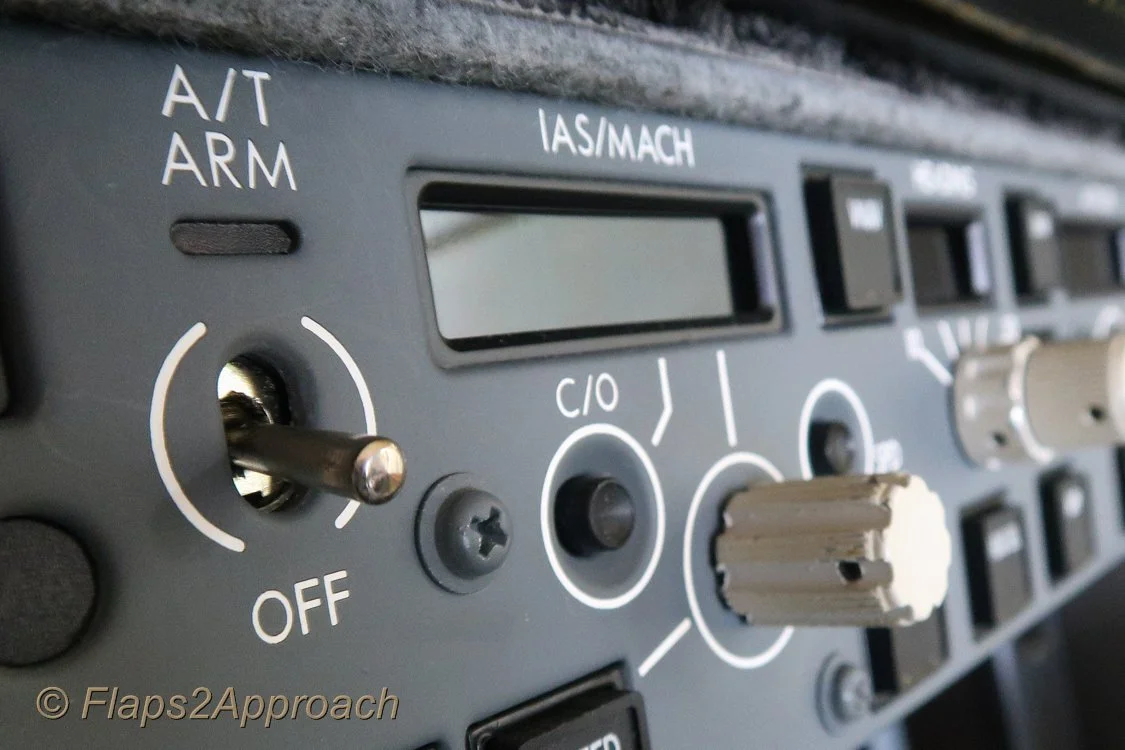
Anatomy of the Toggle Switch

The OEM Light Test switch may appear to be a ‘glorified’ toggle switch with an aviation-sized price tag; however, there is a difference and a reason for this high price tag.  

The switch although relatively simple in output, encompasses 18 (6+6+6) high amperage individual switches assigned to three terminals located on the rear of the switch.  Each terminal can be used to connect to a particular aircraft system, and then to each other.  This allows the toggle switch to turn on or off multiple aircraft systems during the light test. 
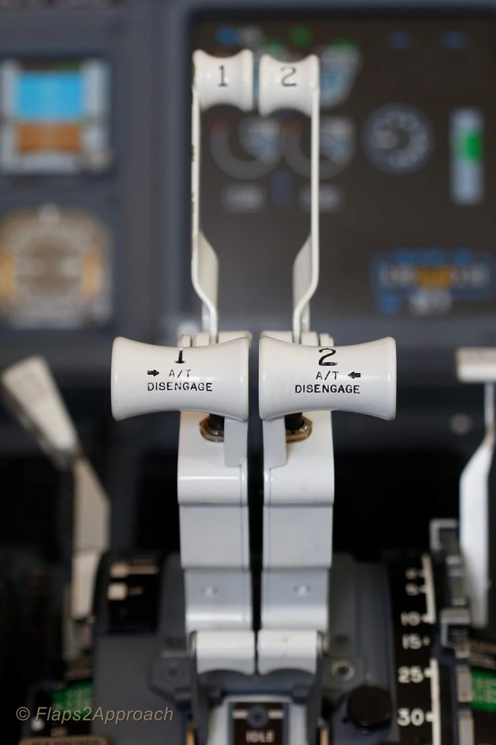
The purpose of these multi-terminals is to allow the toggle switch to cater towards the high amperage flow of several dozen annunciators being turned on at any one time during the lights test, in addition to generators and other aircraft systems that are not simulated in Flight Simulator.  In this way, the switch can share the amperage load that the annunciators draw when activated during the light test.

The switch can control the annunciators (korrys) for the MIP, forward overhead, aft overhead, fire suppression panel and any number of modules located in the center pedestal which use 28 volt korrys.  

OEM Lights Test switch.  The appearance of the OEM switch is not dissimilar to a normal toggle switch; however, the functionality is different in that there are a number of terminals on the rear of the switch to allow multi-system connection

Terminals, Interfacing and Connection

To determine the correct terminals to be used for the light test is no different to a normal toggle-style switch. 

First, ascertain which of the six terminals correlate to the switch movement (toggle up, center and down).  The three unused terminals are used to connect with other systems in the real aircraft (not used in Flight Simulator).

To determine the correct terminals for wiring, a multimeter is set to conductivity (beep) mode.  Place one of the two multimeter prongs on a terminal and then place the other prong on the earth (common) terminal.  Gently move the toggle.   If you have the correct terminal for the position of the toggle, the multimeter will beep indicating an open circuit. The toggle switch does not require a power source, but power is required to illuminate the annunciators during the lights test.  

For an overview of how to use a multimeter see this post - Flight Deck Builders Toolbox - Multimeter.

Daisy Chaining and Systems

Any annunciator can be connected to the light test function, and considering the number of annunciators that the light test function interrogates, it is apparent that you will soon have several dozen wires that need to be accommodated. 

Rather than think of individual annunciators, it is easier to relate a group of like-minded components as a system.  As such, depending upon your simulator set-up, you may have the MIP annunciators as one system, the overhead annunciators as another and the fire suppression panel and modules mounted in the center pedestal as yet another.  If these components are daisy chained together (1+1+1+1+1=connection), only one power wire will be required to be connected at the end of the array.  This minimises the amount of wire required and makes connection easier with the toggle switch.

Two Methods to Connect to the Switch

There are two ways to wire the switch; either through the flight avionics software (software-based solution), or as a stand-alone mechanical system.  There is no particular benefit to either system.  The software solution triggers the lights test by opening the circuit on the I/O cards that are attached to the computer, while, the mechanical system replicates how it is done in the real aircraft.

Switch in-line (software connection using ProSim737)

The on/off terminal of the toggle switch is connected to a Leo Bodnar card or other suitable card (I use a Flight Deck Solutions System card), and the card’s USB cable connected to the main computer.  Once the card is connected, the avionics suite software (ProSim737) will automatically register the card with to allow configuration.  Depending upon the type of card used, registration of the inputs and outputs for the card may first need to be registered in Windows (if using Windows 7/10, type into the search bar joystick and then select calibration).

To configure the toggle switch in ProSim737, open the configuration/switches tab and scroll downward until you find the lights test function.  Open the tab beside the name; select the appropriate interface card (Leo Bodnar card) from the drop down menu and save the configuration.  

ProSim737 will automatically scan the interface cards that are installed, and if there is a card that has a power requirement, such as a Phidget 0/16/16 card (used to convert OEM annunciators, modules and panels), the software will make a connection enabling the lights test to function.

Considering the connection is accomplished within the ProSim737 software, it stands to reason the lights test will only operate when ProSim737 is open.

To illuminate the annunciators when the switch is thrown, a 28 volt power supply will need to be connected to the annunciators either separately or in a daisy chain array.

OEM aviation relay mounted in center pedestal

Stand-alone (mechanical connection)

The second method, which is the way it is done in the real aircraft, is to use an OEM 50 amp 6 pull/6 throw relay. 

Depending upon the type of relay device used (there are several types), it may be possible to connect up to three systems to the one relay.

Lights Test Busbar

Although the lights test toggle switch has the capacity to connect several systems to the actual switch, it would be unmanageable to attempt to connect each panel to the lights test switch.

To solve this issue a centrally-placed aviation-grade relay has been used in association with a busbar.

The benefit of using an OEM relay and busbar is that the relay acts as a central point for all wires to attach.  The wires from the various systems (panels, korrys, etc) attach to the busbar which in turn connects to the various posts on the relay.

When the lights test toggle is positioned to lights test, the relay will open or close enabling power to reach the annunciators (via the busbar).

The stand-alone system will enable the lights test to be carried out without ProSim737 or flight simulator being open.

The OEM relay is not large - the size of a small entree plate, however, it can be problematic finding a suitable area in which to mount the relay where it is out of the way.  A good location is to mount the relay inside the pedestal bay. In my case, the relay is attached to a flat wooden board which is secured to the lower section of the center pedestal.

Using the DIM Functionality (toggle thrown downwards)

This article has only discussed the lights test function of the toggle switch. The DIM function is used to dim the OEM annunciators (korrys) for night work. 


Diagram 1: basic overview to how the oem lights test toggle is connected


diagram 2: flow schematic between oem light test toggle and annunciators


Crosswind Landing Techniques Part Two - Calculations

crosswind landing with right main gear touching first (Jeroen Stroes Aviation Photography from Netherlands, EI-FIZ (27608888537), CC BY 2.0

Determining Correct Landing Speed (Vref)

Vref is defined as landing speed or the threshold crossing speed, while Vapp is defined as the approach speed with wind/gust additives.

When landing with a headwind, crosswind, or tailwind the Vref and Vapp must be adjusted accordingly to obtain the optimal speed at the time of touchdown.  Failure to do this may result in the aircraft landing at an non-optimal speed causing runway overshoot, stall, or floating (ground affect).

Mathematical calculations can be used to determine Vref and Vapp based on wind speed, direction, and gusts.

This is the second segment of a two-segment post.  The first segment dealt with methods used to land in cross wind conditions  - Crosswind Landing Techniques Part One Crab and Sideslip.

Normal Conditions

When using the autothrottle is to be used for landing, position command speed to Vref+5 knots. There is no need to add the wind additive as the autothrottle logic already compensates for gusts through airspeed and acceleration sensing.

If the autothrottle is disengaged or is planned to be disengaged prior to landing, the recommended method to obtain the correct approach speed (Vapp), is to add one half of the reported steady headwind component plus the full gust increment above the steady wind to the reference speed (Vref).

One half of the reported steady headwind component can be estimated by using 50% for a direct headwind, 35% for a 45-degree crosswind, zero for a direct crosswind, or interpolation between.

When making adjustments for wind additives, the maximum command speed should not exceed Vref+20 knots or landing flap placard speed minus 5 knots, whichever is lower.

The minimum command speed setting with autothrottle disconnected is Vref+5 knots.  The gust correction should be maintained to touchdown while the steady headwind correction should be bled off as the airplane approaches touchdown. 

It is important to note that Vref+5 knots is the speed that is desired when crossing the threshold of the runway - it is NOT the approach speed.  The approach speed (Vapp) is determined by headwind with/without gusts.  If the wind is calm, Vref+5 knots will equal Vapp.

When landing in a tailwind, do not apply wind corrections. Set command speed at Vref+5 knots (autothrottle engaged or not engaged).

Non-Normal Conditions

When Vref has been adjusted by the non-normal procedure, the new Vref is called the adjusted Vref and is used for the landing.  To this speed is added the wind component (if necessary).

For example, if a non-normal checklist specifies 'Use flaps 15 and Vref 15+10 for landing', the flight crew would select flaps 15 and look up the Vref 15 speed (in FCTM or QRH) and add 10 knots to that speed.  The adjusted Vref does not include wind corrections and these will need to be added.

If the autothrottle is disengaged, or is planned to be disengaged prior to landing, appropriate wind corrections must be added to the adjusted Vref to arrive at command speed.  Command speed is the safest speed used to fly the approach (Vapp).  If the speed is above command speed then it will need to be bleed off prior to touchdown.

Autoland Limitations

If using autoland (CAT II & CAT IIIA) the autothrottle remains engaged and the command speed is set to Vref+5.

The following autoland limitations must be complied with:

  1. Glide slope angle tolerance - maximum 3.25 degrees / minimum 2.5 degrees;

  2. Engines 1/2 operational;

  3. Maximum​ tailwind - 15 kts​;

  4. Maximum headwind - 25 kts​;

  5. Maximum crosswind - 20​ kts ;

  6. Maximum tailwind at flaps 30 - 12 knots (winglets); and,

  7. Landing in gusty​ wind​ or windshear​ conditions is not approved during CAT II and CAT IIIA operations.

Guideline (an easy way to remember the above - cheat sheet)

This information assumes the autothrottle will be disengaged prior to landing.

  • Headwind less than 10 knots:  Vref+5

  • Headwind greater than 10 knots:  Vref +headwind / 2 (half your headwind) - This is your Vref

  • If Vref is > 20 knots, then:  Vref+20 (as per placard guide)

With Gusts

  • Formula (Wind < 10 knots):  Vref+5 + gust – headwind

  • Formula (Wind > 10 knots):  Vref + headwind/2 (half your headwind) + gust – headwind

Calculating Directional Wind

A wind component will not always be at 90 Degrees or straight on to your landing direction.  The following calculation is often used to determine the directional component.  One half of the reported steady headwind component can be estimated by using 50% for a direct headwind, 35% for 45 degree crosswind, zero for a direct crosswind and interpolation in between.

Tail Winds

Tail winds are very challenging for conducting a stabilized approach.  Because of the increased ground speed caused by a tail wind, Boeing does not publish Vref correction factors for tail winds. 

Typically, to maintain the proper approach speed and rate of descent while maintaining glide slope, thrust must be decreased which minimizes the available safety envelope should a go-around be required.  If a go-around is required, precious seconds might be lost as the engines accelerate; the aircraft would continue to descend and might touch down on the runway before the engines produce enough thrust to enable a climb.

The International Civil Aviation Organization (ICAO) recommends that the tail wind component must not exceed 5 knots plus gusts on a designated runway; however, adherence to this recommendation varies among members.  Several airlines have been certified for operation with a 15 knot tailwind. 

In the United States, Federal Aviation Administration (FAA) sets the tail wind component limit for runways that are clear and dry at 5 knots, and in some circumstances 7 knots, however FAA allows no tail wind component when runways are not clear and dry.  Note, that many manuals subscribe to the 10 knots no tailwind rule (see table below).

Crosswind components can be variable dependent upon flight crew discretion and airline policy; therefore, the above is to be used as a 'guide' only.

The below table (limitations) summarizes much of what has been written above.


table 1: wind limits for 737-800. the table provides a good summary of what has been written in the article


The CDU if configured correctly can provide information concerning wind components.  Press the key on the CDU named 'PROG' followed by 'PREV PAGE'.  This page provides an overview of the wind component including head, tail and crosswind.

Wind Correction Field (WIN CORR)

The approach page in the CDU has a field named WIN CORR (Wind Correction Field or WCF).  Using this field, a flight crew can alter the Vref+ speed (additive) that is used by the autothrottle.  The default reading is +5.   Any change will alter how the FMC calculates the command speed that the autothrottle uses; changes are reflected in the LEGS page.  It's important to update the WIND CORR field if VNAV is used for the approach, as VNAV uses data from the FMC to fly the approach.  If hand flying the aircraft, it's often easier to add the Vref additive to the speed window in the MCP.

WIND CORR Explained

The WCF is a handy feature if a flight crew wishes to increase the safety margin the autothrottle algorithm operates.

Boeing when they designed the autothrottle algorithm programmed a speed additive that the A/T automatically adds to Vref when the A/T is engaged.  The reason for adding this speed is to provide a safety buffer to ensure that the A/T does not command a speed equal to or lower than Vref.   (recall that wind gusts can cause the autothrottle to spool up or down depending upon the gust strength).  

A Vref+ speed higher than +5 can be inputted when gusty or headwind conditions are above what are considered normal.  By increasing the +speed, the  speed commanded by the autothrottle will not degrade to a speed lower than that inputted.

Important Points:

  • During the approach, V speeds are important to maintain.  A commanded speed that is below optimal can be dangerous, especially if the crew needs to conduct a go-around, or if winds suddenly increase or decrease.  An increase or decrease in wind can cause pitch coupling.

  • If using VNAV, it's important to update the WIND CORR field to the correct headwind speed based on conditions.  This is because VNAV uses the data from the FMC.

If executing an autoland (rarely done in the B737), the WIND CORR field is left as +5 knots (default).  The autoland and autothrottle will command the correct approach and landing speed.

Crosswind Landing Techniques Part One - Crab and Sideslip


This video very clearly illustrates my point that landing in a strong crosswind can be a challenging and in some cases downright dangerous (Video © CargoSpotter (with thanks); courtesy U-Tube).

Generally, flight crews use one of two techniques or a combination thereof to approach and land in crosswind conditions.  If winds exceed aircraft tolerances, which in the 737-800 is 33 knots (winglets) and 36 knots (no winglets), the flight crew will divert to their alternate airport (Brady, Chris - The Boeing 737 technical Guide).

crab approach. Wind is right to left at 16 knots with aircraft crabbing into the wind to maintain centerline approach course.  Just before flare, left rudder will be applied to correct for drift to bring aircraft into line with centerline of runway.  This technique is called 'de-crabbing’. During such an approach, the right wing may also be lowered 'a tad' (cross-control) to ensure that the aircraft maintains the correct alignment and is not blown of course by a 'too-early de-crab'.  Right wing down also ensures the main gear adheres to the runway during the roll out

Maximum crosswind figures can differ between airlines and often it's left to the pilot's discretion and experience.  Below is an excerpt from the Landing Crosswind Guidelines from the Flight Crew Training Manual (FCTM).  Note that FCTMs can differ depending on date of publication.

There are several factors that require careful consideration before selecting an appropriate crosswind technique: the geometry of the aircraft (engine and wing-tip contact and tail-strike contact), the roll and yaw authority of the aircraft, and the magnitude of the crosswind component.  Consideration also needs to be made concerning the effect of the selected technique when the aircraft is flared to land.

Crosswind Approach and Landing Techniques

There are four techniques used during the approach and landing phase which center around the crab and sideslip approach.  The crab and sideslip are the primary methods and most commonly used while the de-crab and combination crab-sideslip are subsets that can be used when crosswinds are stronger than usual.

It must be remembered that whatever method is used it is at the discretion of the pilot in command.

  1. Crab (to touchdown).

  2. Sideslip (wing low).

  3. De-crab during flare.

  4. Combination crab and sideslip.

1:  Crab (to touchdown)

  • Airplane maintains a crab during the final approach phase.

  • Airplane touches down in crab.

  • Flight deck is over upwind side of runway (Main gear is on runway center).

  • Airplane will de-crab at touchdown.

  • Flight crew must maintain directional control during roll out with rudder and aileron.

With wings level, the crew will use drift correction to counter the effect of the crosswind during approach.  Drift correction will cause the aircraft to be pointing in a direction either left or right of the runway heading, however, the forward energy of the aircraft will be towards the centerline.  This is called the crab because the aircraft is crabbing at an angle left or right of the aircraft's primary heading.

Most jetliners have the ability to land in a crab, however, it must be remembered that landing in a crab places considerable stress on the main landing gear and tyre side-walls, which in turn can cause issues with tyre and wheel damage, not too mention directional control.

The later is caused by the tandem arrangement of the main landing gear that has a strong tendency to travel in the direction that the nose of the aircraft is pointing at the moment of touchdown.  This can result in the aircraft travelling toward the edge of the runway during the roll out.  To counter this, and align the nose of the aircraft with the centreline of the runway, the pilot flying must apply rudder input when lowering the nose wheel to the runway surface.

A reference to the maximum amount of crab that can be safely applied in the B737 was not found, other than maximum crosswind guidelines must not be exceeded.  The crab touchdown technique is the preferred choice if the runway is wet.

2:  Sideslip (wing low)

  • Upwind wing lowered into wind.

  • Opposite rudder (downwind direction) maintains runway alignment.

  • In a sideslip the aircraft will be directly aligned with the runway centerline using a combination of into-wind aileron and opposite rudder control (called cross-controls) to correct the crosswind drift.

The pilot flying establishes a steady sideslip (on final approach by applying downwind rudder to align the airplane with the runway centerline and upwind aileron to lower the wing into the wind to prevent drift.  The upwind wheels should touch down before the downwind wheels touch down.

The sideslip technique reduces the maximum crosswind capability based on a 2/3 ratio leaving the last third for gusts.  However, a possible problem associated with this approach technique is that gusty conditions during the final phase of the landing may preempt a nacelle or wing strike on the runway.

Therefore a sideslip landing is not recommended when the crosswind component is in excess of 17 knots at flaps 15, 20 and 30, or 23 knots at flaps 40.

The sideslip approach and landing can be challenging both mentally and physically on the pilot flying and it  is often difficult to maintain the cross control coordination through the final phase of the approach to touchdown.  If the flight crew elects to fly the sideslip to touchdown, it may also be necessary to add a crab during strong crosswinds.

3:  De-crab During Flare(with removal of crab during flare)

  • Maintain crab on the approach.

  • At ~100 foot AGL the flight crew will de-crab the aircraft; and,

  • During the flare, apply rudder to align airplane with runway centreline and, if required slight opposite aileron to keep the wings level and stop roll.

This technique is probably the most common technique used and is often referred to as the 'crab-de-crab'.

The crab technique involves establishing a wings level crab angle on final approach that is sufficient to track the extended runway centerline.  At approximately 100 foot AGL and during the flare the throttles are reduced to idle and downwind rudder is applied to align the aircraft with the centerline (de-crab). 

Depending upon the strength of the crosswind, the aircraft may yaw when the rudder is applied causing the aircraft to roll.  if this occurs, the upwind aileron must be placed into the wind and the touchdown maintained with crossed controls to maintain wings level (this then becomes a combination crab/sideslip - point 4).

Upwind aileron control is important, as a moderate crosswind may generate lift by targeting the underside of the wing. Upwind aileron control assists in ensuring positive adhesion of the landing gear to the runway on the upwind side of the aircraft as the wind causes the wing to be pushed downwards toward the ground.

Applied correctly, this technique results in the airplane touching down simultaneously on both main landing gear with the airplane aligned with the runway centerline.

4:  Combination Crab and Sideslip

  • De-crab using rudder to align aircraft with runway (same as point 3 de crab during flare).

  • Application of opposite aileron to keep the wings level and stop roll (sideslip). 

The technique is to maintain the approach in a crab, then during the final stages of the approach and flare increase the into-wind aileron and land on the upwind tyre with the upwind wing slightly low.  The combination of into-wind aileron and opposite rudder control means that the flight crew will be landing with cross-controls.

The combination of crab and sideslip is used to counter against the turbulence often associated with stronger than normal crosswinds.

As with the sideslip method, there is the possibility of a nacelle or wing strike should a strong gust occur during the final landing phase, especially with aircraft in which the engines are mounted beneath the wings.

FIGURE 1:  Diagram showing most commonly used approach techniques (copyright Boeing)

Operational Requirements and Handling Techniques

With a relatively light crosswind (15-20 knot crosswind component), a safe crosswind landing can be conducted with either; a steady sideslip (no crab) or a wings level, with no de-crab prior to touchdown.

With a strong crosswind (above a 15 to 20 knot crosswind component), a safe crosswind landing requires a crabbed approach and a partial de-crab prior to touchdown.

For most transport category aircraft, touching down with a five-degree crab angle with an associated five-degree wing bank angle is a typical technique in strong crosswinds.

The choice of handling technique is subjective and is based on the prevailing crosswind component and on factors such as; wind gusts, runway length and surface condition, aircraft type and weight, and crew experience.

Touchdown Recommendations

No matter which technique used for landing in a crosswind, after the main landing gear touches down and the wheels begin to rotate, the aircraft is influenced by the laws of ground dynamics.

Effect of Wind Striking the Fuselage, Use of Reverse Thrust and Effect of Braking

The side force created by a crosswind striking the fuselage and control surfaces tends to cause the aircraft to skid sideways off the centerline.  This can make directional control challenging.

Reverse Thrust

The effects of applying the reverse thrust, especially during a crab ‘only’ landing can cause additional direction forces.  Reverse thrust will apply a stopping force aligned with the aircraft’s direction of travel (the engines point in the same direction as the nose of the aircraft).  This force increases the aircraft’s tendency to skid sideways.

Effects of Braking

Autobrakes operate by the amount of direct pressure applied to the wheels.  In a strong crosswind landing, it is common practice to use a combination of crab and sideslip to land the aircraft on the centerline.  Sideslip and cross-control causes the upwind wing to be slightly down upon landing and this procedure is carried through the landing roll to control directional movement of the aircraft. 

The extra pressure applied to the ‘wing-down’ landing gear causes increased auto-braking force to be applied which creates the tendency of the aircraft to turn into the wind during the landing roll.  Therefore, a flight crew must be vigilant and be prepared to counter this unwanted directional force.

If the runway is contaminated and contamination is not evenly distributed, the anti-skid system may prematurely release the brakes on one side causing further directional movement.

FIGURE 2:  Diagram showing recovery of a skid caused by crosswind and reverse thrust side forces (source: Flight Safety Foundation ALAR Task Force)

Maintaining Control - braking and reverse thrust

If the aircraft tends to skew towards the side from higher than normal wheel-braking force, the flight crew should release the brakes (disengage autobrake) which will minimize directional movement.  

To counter against the directional movement caused by application of reverse thrust, a crew can select reverse idle thrust which effectively cancels the side-force component.  When the centerline has been recaptured, toe brakes can be applied and reverse thrust reactivated.

Runway Selection and Environmental Conditions

If the airport has more than one runway, the flight crew should land the airplane on the runway that has the most favourable wind conditions.  Nevertheless, factors such as airport maintenance or noise abatement procedures sometime preclude this.

I have not discussed environmental considerations which come into play if the runway is wet, slippery or covered in light snow (contaminated).  Contaminated conditions further reduce (usually by 5 knots) the crosswind component that an aircraft can land.

Determining Correct Landing Speed (Vref)

Vref is defined as landing speed or threshold crossing speed.

When landing with a headwind, crosswind, or tailwind the Vref must be adjusted accordingly to obtain the optimal speed at the time of touchdown.  Additionally the choice to use or not use autothrottle must be considered. Failure to do this may result in the aircraft landing at a non-optimal speed causing runway overshoot, stall, or floating (ground affect).

This article is part one of two posts.  The second post addresses the calculations required to safety land in crosswind conditions: Crosswind Landing Techniques Part Two Calculations.

OEM Brackets to Secure Gauges and Modules to Boeing 737 MIP

oem brackets. brackets for different sized modules and gauges.  The brackets when tightened provide a snug and secure fit for any OEM gauge or module

Original Equipment Manufacturer (OEM) parts usually attach to the infrastructure of the flight deck by the use of DZUS fasteners.  The easy to use fasteners allow quick and easy removal of panels and modules.  But what about the gauges that are used in the Main Instrument Panel (MIP); for example, the yaw dampener, brake pressure and AFDS module.

These items do not use DZUS fasteners for attachment to the MIP; rather they are inserted into the MIP from the front and secured from behind by a specially designed bracket.  The different sized brackets are made from lightweight aluminum and are designed to fit particular gauges and modules.   Each bracket incorporates, depending on the style, a number of screws.  These screws are used to loosen or tighten the bracket. 

The gauge is inserted into the MIP from the front.  The bracket is then placed over the gauge from behind the MIP and tightened by one or more of the resident screws.  The screws cause the bracket to clamp tightly to the shaft of the gauge and ‘sandwich’ the MIP between the flanges of the gauge and the edge of the bracket.  Once fitted, the Canon plug is then re-attached to the gauge.

selection of oem and reproduction gauges (flaps is reproduction)

Of interest is that some brackets have been designed to fit the differing thicknesses between MIPs.  By turning the bracket end on end the appropriate thickness of the MIP is selected.  

As mentioned above, the brackets are designed to fit specifically sized and shaped gauges and modules; therefore, it is important to purchase the bracket that fits the gauge you are using.  There are several different sized brackets on the market that are used in the Boeing 737 classics and NG airframes.  The 'NG' for the most part incorporates identically sized gauges as the classics, so a bracket is not necessarily NG specific.

One of the benefits in using the OEM brackets is that they are designed for the purpose, are very easy to install, and facilitate the quick removal of a gauge or module should it be necessary.

In the next post we look more at flight training and discuss crosswind landings.

Approach Tools: Vertical Bearing Indicator, Altitude Range Arc and Vertical Deviation Scale

  • THIS ARTICLE IS UNDER REVIEW - EXPECT MINOR CHANGES…. (9 September 2025)

On 12 February 2012, the flight crew of a Boeing 737 aircraft, registered VH-TJS and operated by Qantas Airways Limited, was conducting a scheduled passenger service from Sydney, New South Wales to Canberra, Australian Capital Territory. Due to scheduled maintenance the instrument landing system at Canberra was not available and the crew prepared for an alternate instrument approach that provided for lateral but not vertical flight path information. The flight was at night with rain showers and scattered cloud in the Canberra area.

Shortly after becoming established on the final approach course with the aircraft’s automatic flight system engaged, the flight crew descended below the minimum safe altitude for that stage of the approach. The crew identified the deviation and leveled the aircraft until the correct descent profile was intercepted, then continued the approach and landed. No enhanced ground proximity warning system alerts were generated, as the alerting thresholds were not exceeded.

During those phases of flight when terrain clearance is unavoidably reduced, such as during departure and approach, situation awareness is particularly crucial. Any loss of vertical situation awareness increases the risk of controlled flight into terrain. This occurrence highlights the importance of crews effectively monitoring their aircraft’s flight profile to ensure that descent is not continued through an intermediate step-down altitude when conducting a non-precision approach (Australian Transport safety Bureau, 2013).

Determining the correct rate of descent (RoD) or vertical speed (V/S) is a critical attribute if an aircraft is to arrive at the correct altitude and avoid excessive descent rates.  Control of the vertical path uses two different methods: the step-down method and the constant descent method.  Both methods assume that the aircraft is being flown in landing configuration at the final approach speed (VaPP) from the final approach fix (FAF) to the landing initiation of the missed approach.

Non Precision Approaches (NPA)

Historically, non precision approaches reference ground navigation aids that exhibit a degree of inaccuracy, which is often enhanced by the poorly defined vertical path published on an approach chart; NPA charts typically provide only an assigned altitude at the FAF and the distance from the FAF to the MAP.  Thus, flight crew awareness of the aircraft’s vertical position versus the intended vertical path of the final approach can be quite low when executing traditional style step-down approaches.

Flight crews today, especially those flying in and out of busy intercity hubs, rarely execute step down approaches as computer and GPS-orientated systems have replaced traditional methods of navigation.  However, as the flight into Canberra revealed, the best system may at times be inoperative or fail and it is good airmanship to understand and be able to remember one or more of the below- mentioned equations. 

Today's avionics systems provide a high level of redundancy and the Boeing 737-800 NG incorporates a number of integrated aids to assist a flight crew during descent and approach.  In this article, I will discuss the following:

  • Calculations to determine rate of descent and glide path;

  • Vertical Bearing Indicator (VBI);

  • Altitude Range Arc; and,

  • Vertical Development (VERT DEV).

Rate of Descent & Glideslope Calculations

To determine the best vertical speed to use during a non precision approach, flight crews regularly use a number of 'back of the envelope' calculations to determine rate of descent and glide path – some more accurate than others.  Search ‘determine descent rate’ in Google.  Some of the more commonly used rules of thumb are:

  • Divide your ground speed by 2, then add a zero (120 kias / 2 = 60, add 0 = 600 fpm).

  • Rate of descent (RoD) in ft/min should be equal to 5 times the ground speed in knots (same as above but different calculation).

  • To maintain a stabilized approach, add a zero to your indicated air speed and divide by two (150 kias + 0 = 1500 / 2 = 750 fpm).

  • To determine distance from threshold to start a 3 degree glideslope, take the height above ground level and divide by three hundred (600 ft AGL / 300 = 2 nm).

  • To maintain a 3 degree glideslope (ILS), multiply your ground speed by 5.  The resulting number is the rate of descent to fly (110 kias x 5 + 550 fpm on 3 degree glideslope).

  • If the glideslope is not operational on an ILS approach with DME, multiply the distance ‘to go’ by 300.  This will provide the height in feet above the threshold of the runway (4 nm to the threshold; multiply x 300 = 1200 ft).

CDU showing DES Page, waypoint/altitude and VBI interface (Key RSK3 & RSK4)

Vertical Bearing Indicator (VBI)

A tool often overlooked with regard to positional awareness is the Vertical Bearing Indicator (VBI). The VBI display is part of the Descent page in the CDU. 

Reading through the literature there is very little application of this tool published in the Flight Crew Training Manual (FCTM). What information that is available comes from real world line pilot experience and through aftermarket publications such as the FMC Users Guide by Bill Bulfer.

Before continuing, flight simulation avionics packages can differ; often these differences reflect on the flight management software used (U number), however, sometimes the software has not been modeled correctly. The information in this article reflects the real avionics suite used in the 737.

The VBI can calculate an accurate rate of descent to a particular spatial point.  It is basically an angle calculator that provides ‘live’ vertical speed information based upon a desired descent angle, the current speed of the aircraft and an end location. The VBI can interrogate information from any navigation source whether it be a waypoint, point along route waypoint, nav aid, such as a VOR, or runway designation.

The application of the VBI is varied, however, in its simplest application, the flight crew enters into the VBI a waypoint and final altitude that the aircraft should be at, for example, the Initial Approach or Final Approach Fix could be used or perhaps the landing runway threshold. This figure is determined by consulting the appropriate approach chart for the airport.  Once the information is imported into the VBI, the FMC will calculate the descent rate based on flight variables.  As the aircraft descends, the VBI readout will continually update the descent rate based upon aircraft speed and rate of descent.

The flight crew can either manually fly the aircraft using the descent rate information as a guide, or use part or full automation to maintain the rate of descent.  A common method is to use the Vertical Speed (V/S) function in the MCP.

It is important to understand that the VBI has nothing to do with VNAV; the VBI will function no matter if VNAV is selected or not.  The VBI takes the raw distance between the aircraft and a selected altitude point and calculates a vertical bearing to that point.  If that point is part of a route in the CDU, then the next altitude constraint will be displayed, unless the user changes this.

If a route has not been programmed into the CDU, or a point in space along the route is required that is not a waypoint, then the waypoint will need to be created using the FIX page in the CDU. To learn how do do this see: Creating Waypoints On The Fly.

The VBI provides 3 fields:

  • FPA (Flight Plan Angle) is the vertical path in degrees that the aircraft is currently flying.

  • V/B (Vertical Bearing) is the vertical path in degrees that the aircraft SHOULD be flying to reach the imported waypoint at the desired altitude.

  • V/S (Vertical Speed) is the vertical bearing (V/B) converted into vertical speed for easy input into the V/S window in the MCP.

The VBI can be used in a number of scenarios and, once its fullest potential is understood, can be used along with the FIX function in the CDU to create additional waypoints and interception points from which descent data can be obtained. Possible scenarios that the VBI can be used are in a:

  • Approach from downwind;

  • Approach from base;

  • Straight-in approach;

  • Circling Approach;

  • Arc approach; and,

  • Descent from altitude to a waypoint, Initial Approach Fix (IAF) or Final Approach Fix (FAF).

One of the main advantages in using the VBI is that the pilot can instigate an accurate controlled idle descent, following a desired glide path to the desired waypoint.

Accessing the VBI

Navigate to Descent page in the CDU by pressing the DES key.

At lower right hand side of the DES page you will see the following: FPA, V/B, V/S.  This is the Vertical Bearing Indicator.

Key RSK3 (right line select 3) allows manual entry of a waypoint and altitude or altitude.  There are a few ways to import the data to the VBI. Either:

  1. Type the waypoint and altitude separated by the / slash symbol into the scratchpad of the CDU and upload to the correct line. An example being BUSKA/4200, or if desiring the landing runway RWxx followed by a forward slash (RWxx/) or RWxx followed immediately by /-0.1 (RWxx/-0.1) - which is used depends on the avionics software in use. The forward slash (/) enables the VBI to auto-populate the altitude with the touchdown zone elevation (TSZE) for the runway ); or,

  2. Opening the LEGS page select the appropriate waypoint wanted, download this to the scratchpad and then upload the information directly to the VBI. The same procedure is used to insert the landing runway.

  3. If an along route waypoint has been created in the FIX page, then this information will need to be downloaded to the scratchpad and then uploads to the VBI.

Important Points:

  • The information and navigation data that can be displayed by the VBI (both in the CDU and ND) is paramount in enhancing spacial awareness, especially for approaches that are not straight-in.

  • There are several ways that the VBI can be used. I urge you to experiment.

  • The VBI is a straightforward to tool to use once you have an understanding of the three variables (flight path, vertical bearing and vertical speed).

Using The VBI (for example to change altitude)

  1. Enter the required information into the VBI (waypoint and altitude - WPT/ALT).

  2. Watch the V/B and wait until the V/B moves between 2.7 and 3.0 degrees (or whatever descent angle you require).

  3. When the value is displayed in the VBI, dial the new altitude and V/S into the MCP. The Autopilot, if selected, will follow the V/S.

  4. If VNAV is selected, and a VNAV descent is commanded prior to reaching the Top of Descent (ToD), the Flight Management System (FMS) will command a 1250 fpm descent rate until the displayed V/B is captured before following the vertical bearing.

An Introduction to VBI (courtesy 737 Captain A. Asiri, U-Tube)

The VBI can also be used during the approach. Insert the landing runway information into the VBI, for example, RWxx and the VBI will update the flight path angle, vertical bearing and vertical speed to the runway. The vertical speed information can be dialed directly into V/S in the MCP or it can be used solely as a reference if hand flying the aircraft.

The runway information can either be downloaded to the scratchpad in the CDU by selecting the RWxx in the LEGS page, and then uploading to the VBI, or the information can be typed into the scratchpad and uploaded separately. If the later is used, type the runway number followed by a forward slash. For example, RW12/.

Important Points:

  • The idle descent in a 737 is roughly 3.0 degrees.

  • The VBI can be used for any waypoint, fix and altitude and acts in conjunction with the AFDS

  • The vertical bearing when the aircraft is on final approach calculates data from the Final Approach Fix (FAF) to the runway threshold.

VBI and ProSim737

It has been mentioned that the VBI may function differently between avionics suites (U number) and software manufacturers. At the moment, ProSim737 (as at September 2024 running Version 3.24b29) does not replicate fully the functionality of the VBI. The WPT/ALT should be able to be overwritten at anytime during a flight. ProSim737 does not do this. Instead, the WPT/ALT can only be overwritten when the Vertical Deviation Scale (VDS) is displayed on the ND. This usually occurs when the aircraft has reached Top of Descent (ToD).

I assume that this shortfall will be rectified in upcoming releases.

737-800 Altitude Range Arc and Vertical Deviation Scale with Pointer. Hi / Low numbers are not displayed as aircraft is on target for vertical descent

Altitude Range Arc (ARA)

A helpful feature often overlooked is the Altitude Range Arc (ARA).  The ARA is a green coloured half semicircle which can be viewed on the Navigation Display (ND).  The ARA indicates the approximate position on the map where the altitude, as set on the MCP is expected to be reached. 

The ARA will be displayed whenever the altitude has been changed in the MCP and a descent mode selected (for example, Level Change or V/S).

Initially the line will advance and contract, but once the aircraft is established on the descent profile the semicircle should come to rest on the next targeted waypoint.  

Important Point:

  • The ARA is a reference to the approximate position that the aircraft will be at if conditions remain as they are. It is guide.

Vertical Deviation Scale and Pointer (VDS) & Vertical Development (VERT DEV)

The Vertical Deviation Scale is another feature often misunderstood.  The scale can be found on the lower right hand side of the Navigation Display (ND). The scale is also duplicated on the Primary Flight Display (PFD). The scale is often cross referenced to Vertical Development (see below).

Montage showing Vertical Deviation Scale & vertical development display on PFD, ND and CDU respectively

The VDS is a solid white-coloured vertical line with three smaller horizontal lines at the upper, lower and middle section, on which a travelling magenta-coloured diamond is superimposed.  The middle horizontal line represents the aircraft’s position and the travelling diamond represents the vertical bearing (V/B). 

The VDS display represents the aircraft’s vertical deviation from the FMC’s determined descent path (vertical bearing) within +- 400 feet.  It operates in a similar way to the Glideslope Deviation Scale on the Instrument Landing System (ILS).

When the aircraft is within +- 400 feet of the vertical bearing, the diamond will begin to move, indicating that the aircraft is above, below or on the V/B target.  When the aircraft is on target (middle horizontal line), the FMA will annunciate IDLE thrust mode followed by THR HLD as the aircraft pitches downwards to maintain the vertical bearing to the next waypoint.

Important Point:

  • For the VDS to be displayed, a descent and approach profile must be selected from the CDU. The VDS will be displayed no matter what type of approach is used (RNAV, VNAV, VOR, etc).

In some literature this tool is referred to as the Vertical Track Indicator (VTI).

Vertical Development (VERT DEV)

Vertical Deviation Scale and Vertical Development in PFD, ND and CDU

The Vertical Development (VERT DEV) display can be found in the Descent page in the CDU. The displayed number is the numerical equivalent of the Vertical Deviation Scale.  The Vertical Development will display HI or LO prefixed by a number which is the feet the aircraft is above or below the desired glide path; the number will be displayed after the discrepancy has exceeded 50 feet. This information is also duplicated by the display of white-coloured numerals beneath the Vertical Development Scale in the ND.

The Vertical Deviation Scale and Vertical Development display will remain visible on the PFD, ND and CDU throughout the approach. Both tools are important aids to cross reference during a Non Precision Approach (NPA). 

Additional Information

Final Call

The traditional method of a step down approach, which was the mainstay used in the 1970s has evolved with the use of computer systems and GPS.  In the 1980s RNAV (area navigation) approaches with point to point trajectories began to be used, and in the 1990s these approach procedures were further enhanced with the use of Required Navigational Performance (RNP) in which an aircraft is able to fly the RNAV approach trajectory and meet specified Actual Navigation Performance (ANP) and RNP criteria.  From the 1990s onward with the advent of GPS, the method that non precision approaches are flown has allowed full implementation of the RNP concept with a high degree of accuracy.

Although the nature of non precision approaches has evolved to that of a 'precision-like' approach with a constant descent angle, there are operators that widely use these techniques, despite their flaws, weaknesses and drawbacks. Even if modern navigational concepts are used in conjunction with traditional methods, aids such as the Vertical Bearing Indicator, Altitude Range Arc and the Vertical Development display should not be overlooked.  Appropriate cross checking of the data supplied by these aids provides an added safety envelope and avoids having to remember, calculate and rely on ‘back of the envelope’ calculations.

The flight crew landing in Canberra, Australia did not use all the available aids at their disposal.  If they had, the loss of vertical situational awareness may not have occurred.

  • UPDATED: 02 September 2025

Abbreviations

  • ALT - Altitude

  • ANP - Actual Navigation Performance

  • ARA - Altitude Range Arc

  • CDU – Control Display Unit (used by the flight crew to interface the with the FMC)

  • FAF - Final Approach Fix

  • FMS – Flight Management System

  • FMA – Flight Mode Annunciation

  • FMC – Flight Management Computer (connects to two CDU units)

  • ILS – Instrument Landing System

  • KIAS - Knots Indicated Air Speed

  • MAP - Missed Approach Point

  • MCP – Mode Control Panel

  • ND – Navigation Display

  • NPA – Non Precision Approach

  • RoD – Rate of Descent

  • RNP - Required Navigation Performance

  • RNAV - Area Navigation

  • TDZE - Touchdown Zone Elevation (runway threshold)

  • ToD – Top of Descent

  • V/B – Vertical Bearing

  • VBI – Vertical Bearing Indicator

  • V/S – Vertical Speed

  • VDS – Vertical Deviation Scale and pointer (also called Vertical Track Indicator)

  • VERT DEV – Vertical Development

  • WPT - Waypoint