Adding A New Forward Section To The Existing Platform

nicolson rotary router

After spending time working with some minor, but frustratingly time consuming 'teething problems' with the throttle quadrant, I decided it was time to do something different.  Therefore, I have added a meter or so to the front of the platform.  The reason for the addition was to make an area on the platform for the computers and power supplies to reside, rather than just sit on the floor of the room.

Addition From Wood - Not Aluminum

To use aluminium for the forward addition is a  waste of material and resources.  After all, the forward section of the platform is located behind the Main Instrument Panel (MIP) and is not readily visible.  I have used wood obtained from the local recycling center - I enjoy recycling products as much as possible... 

The platform I am using is modular, and it's comparatively easy to add sections to increase its overall size.

In the photograph above, a Nicolson router is being used  to make the circular holes that will be used to route the cables from the throttle quadrant to the Interface Master Module (IMM) and computer.   .

Nicolson Tools (USA)

Nicolson tools are made in the USA and the company produces very heavy and beefy products; the very sharp router made short work of the 2 cm thick wood

The forward platform addition will fit snugly against the existing aluminium platform and blend almost seamlessly.

Other articles dealing with the floor structure can be read below.

Modular Floor Structure / Base Platform Installed

Portion of floor structure showing modules bolted together with control columns and rudder pedals installed to structure

Although it has taken longer than anticipated, the second platform to replace the platform made from wood and MDF fibreboard has been completed. 

The new design is constructed from aluminium flat tubing, is modular, and incorporates the mechanical hardware needed for operation of the OEM 737 control columns. 

The structure comprises two main sections - the modular floor structure, and floor (called the base platform).

Centre platform with ABS plastic floor structure attached. Note the shiny appearance.  This was later removed by painting

The modular design of the platform, which in addition to allowing easy disassembly and transport (if required), also allows the platform to be increased in size by adding further modules.  For instance, if I decide to add an instructor station in the future it will be straightforward to manufacture another module and bolt it to the existing framework.  The hollow underneath section also provides an ideal area for the hidden storage of wires, power boards, and other pieces of necessary equipment such as external speakers and sound systems.

Two aft modules with flooring fitted, rudder pedals in background on forward command module

Access to the underside of the base platform (floor) is via several well-positioned hatches.  Removal of a hatch (4 screws) enables access to whatever is beneath the floor.The platform comprises ten modules which are bolted together at strategic locations to ensure the structure is rigid, strong and sturdy.  Each module has several cross stays that have been welded in place ensuring adequate support for the weight which will be placed on the platform (Weber seats, MIP, throttle unit and people).

The first three modules, which I call the command module, have been constructed as one unit and house the rudder pedals, control columns and incorporate the duel linkage rods and other mechanical hardware for control column and rudder pedal operation.  Although this unit can be separated into the three modules (by removing the attachment bolts, springs and linkage rods),

Half circle flange and seal around control column and drill holes through floor that match corresponding hole in aluminium framework.  Bolts have been used to secure Weber seats.  In the second picture of this series, you can see the claw feet secured by four bolts through the flooring to the support beneath

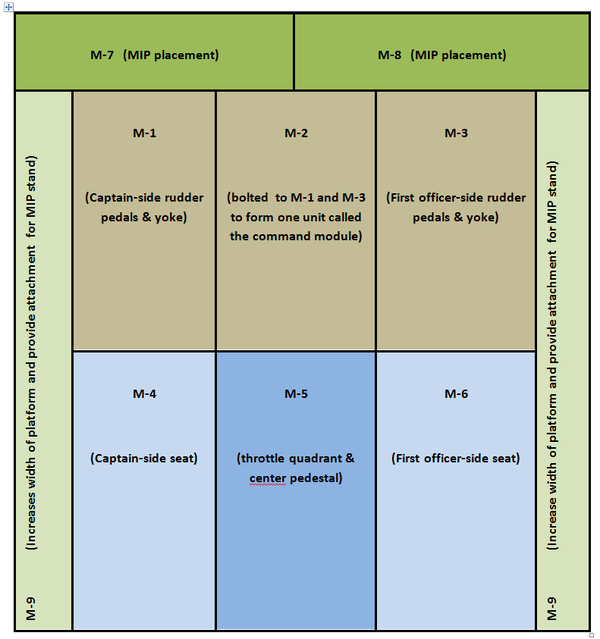
it’s best to leave them attached, as removing the steering mechanism and associated equipment is a complicated and timely operation.

Behind the forward command module are three secondary modules to allow attachment of the two Weber seats and throttle quadrant.  The MIP is attached to two smaller and narrower modules bolted at the front of the command module; whilst at each side two longer and narrow modules provide side support. 

Platform Height and Dimensions

The height of the platform measures 16 cm (6.3 inches) and the total weight, including the two rudder pedals, internal mechanisms and control columns is approximately 160 kilograms (353 pounds).  At this weight, it certainly will not be sliding anywhere.

The platform is not a full size platform as space availability at the current time is limited, however, if and when I wish to move into a full size platform, it will be easy to incorporate and bolt additional correctly sized modules to the existing structure.

Installing Weber Seats

The Weber seats need additional support as seat movement can generate stress at the connection point of the claw feet and floor.  To ensure the seats fitted securely and any stress of seat movement was absorbed by the platform and not just the floor structure, the claw feet bolt directly through the floor to the aluminium tubing structure.  Therefore, the platform absorbs the stress when the seats are moved rather than the flooring.

Platform Floor - ABS Plastic

In the real aircraft the floor is made from pressed aluminum which is studded (rivets) in strategic locations to ensure it is solidly fixed.  Various hatches (hinged and otherwise) are present in certain areas to facilitate access to areas beneath the sheeting.

Builders use many different products for the floor, ranging from MDF fibreboard, ply and aluminium to tin or plastic.  I was intending to use thin aluminium sheeting as a platform floor, however, when I discovered the price I decided to use something less conventional.

A supply of heavy duty ABS plastic was readily available; the advantage of this material being it doesn’t require painting as it’s already coloured Boeing grey, is easy to cut and work with, is of a thickness and weight that can withstand the intended weight and finally, doesn’t flex.  Rather than use one large sheet of board for the platform cover, which would be unmanageable, the sheet has been cut to fit each corresponding module.  The sheets are attached to the aluminium tubing of the module by normal stainless screws. If the material doesn’t hold up to my expectations, I’ll replace it with aluminium or quality ply board. 

Although the ABS plastic is coloured grey, I found it to be too shinny in appearance.  Preparing the ABS plastic for painting was straightforward and entailed thoroughly cleaning the plastic with detergent to remove any residue oil.  Then the plastic was lightly scoured using a low grade sandpaper.  This creates a suitable texture for the paint to adhere.  The ABS sheeting was then painted with one coast of epoxy plastic primer and two coats of matt Boeing grey. 

The ABS plastic and paint has held up to use very well.  Even after scuffing, and moving the throttle quadrant onto and off the floor several times the paint and plastic has not been damaged.

One downside of using ABS plastic can be electrostatic discharge.  If you wear socks on the platform and rub your feet on the ABS plastic a charge can build-up.  I have yet to discover a way to stop this from occurring (other than wearing shoes).

Perhaps I will upgrade the ABS floor at some stage to a full aluminium floor, but at the moment I am more than content with the use of ABS plastic.

Tyre inner tube cut and stretched to fit beneath control column flange.  The overlapping area of rubber tube sits over the bulbous part of the control column lever with the floor

Installing the Control Columns, Rudder Pedals and Column Flange

The floor has been cut and the hole shaped to accommodate the control columns and rudder pedals.  The various linkage rods and internal mechanisms have either been either bolted or welded directly to the lower platform superstructure.

The half circle flange (or whatever Boeing call it) that surrounds each control column on the floor was constructed from light metal.  To replicate the rubber-like seal that is often observed above at the lower end of each control column, a piece of recycled inner tyre tube was used.  The rubber was cut and easily stretched to fit beneath the half circle flange. 

The Main Instrument Panel (MIP) is secured to the platform by several bolts strategically placed on the MIP.

Computer and Sound System Installation

The two computers that are needed to operate the simulator will be positioned at the front of the platform where access is relatively easy to both power supplies and the MIP.  The sound system, which comprises three speakers and a sub-woofer speaker, will be placed directly beneath the floor structure. In the first picture, you can just see the sub-woofer speaker towards the end of the platform.

New Platform Verses Former Platform

The structure of the first platform was from wood, and access to the underside of the platform from the side was next to impossible.  The floor was made from two large sheets MDF fibreboard and although sealed and painted, still appeared to release gases (MDF fibreboard releases gas and requires sealing for indoor use).  The structure and flooring was very solid, but access to anything beneath the floor (maintenance) was difficult.

BELOW:  Diagram layout of modular design.


Update

on 2016-07-19 23:25 by FLAPS 2 APPROACH

Several individuals have requested the dimensions of the platform, which is smaller than a standard platform.  The benefit on being modular is that you can easily add sections to the platform to increase its size.

Platform Size

  • Overall Length:  183 cm

  • Overall Width:  183 cm

  • Height:  16 cm

  • Module M7: Overall Length: 183 cm (each piece left and right is 83.5 cm in length)

  • Module M7: Width 15.5 cm

  • Module M9: Length 167 cm

  • Module M9: Width 15.5 cm

  • Module M1, M2 & M3: Length 85 cm

  • Module M1, M2 & M3: Width 53 cm

  • Module M4, M5 & M6:  Length 81 cm

  • Module M4, M5 & M6:  Width 53 cm

If you are attempting to accommodate a OEM 737 column linking mechanism, the height of the platform will need to be considerably higher (in the order of 10-12 inches height) to house the lower cog mechanism of the columns.

Construction Commenced - New Platform to Install OEM Control Columns

I thought it time to post what’s happening with regard to the construction of the simulator.  Additions and improvements are in the pipeline and it’s hoped that OEM control columns and a new platform will be installed very shortly.

Currently the simulator is mounted on a fiber-board and wood platform, which I constructed when I received my Main Instrument Panel (MIP) just before Christmas 2010.  The platform has served me very well and was perfect for the installation of the ACE yoke and Precision Flight Controls (PFC) rudder pedals.  

Soon after constructing the platform and purchasing the ACE yoke, I was able to secure two OEM B737-500 control columns. I was surprised to find these units so quickly and I was fortunate that my timing coincided with the dismantling of a late model B737-500.

Fitting the OEM control columns to the wooden platform appeared to be problematic, as the platform was a tad low in height and it was awkward to retrofit the linking rod that connects the control columns for duel operation.  Therefore, I decided that a new platform was required; custom designed  to fit the control columns.

Aluminium Modular Design

Rather than use wood and fiber-board, I selected aluminium tubing cut appropriately and TIG welded together.  To facilitate future transport, the platform has been constructed in modular form.  The forward portion comprises three modules bolted together in strategic places, while the rear part of the platform (not shown), where the seats and center pedestal reside, abuts snugly to the forward section.  It’s intended to use high density ¼ inch plastic/vinyl as the upper cover on the platform  as this material is easier to work than aluminium sheeting, is light in weight, very strong and comes from the factory in Boeing grey.

In the photographs (click to enlarge) you can see the control columns (striped completely) fitted to the forward modular section of the platform.  The control columns are connected to each other by a ¾ inch heavy duty shaft and heavy-duty double bearings.  Forward and aft movement of the control column is controlled by a heavy duty spring and left and right roll movement is controlled by another spring. 

Control Column Pull Pressures

The pull pressure on the control column is set to 24 pound which is slightly less that the standard pull in the B737 which is 34 pound.  The pull can be easily altered by moving the spring forward or backward on the spring retainer.  The pressure on the roll component is presently 12 pounds.  I've been told the roll pressure as per the Boeing maintenance manual is +_15 pound; therefore, I'm well within the ball park.

Platform Construction

737-300 throttle quadrant and wooden sectionised platform

A simulator of this size cannot sit on the floor.  There has to be space beneath the simulator to accommodate the control columns and rudder pedal assemblies.  There are many methods used to construct a platform - some very fancy using sheet metal and aluminum  and others quite bland using second hand timber. 

The platform must be constructed so that the surface of the stage is strong enough to hold the weight of two seats, a MIP, a throttle quadrant, center pedestal and two people.  The main area that strength is required is from the central area toward to the rear of platform; this is the area that the seats and throttle quadrant sit.  The areas immediately in front of this doesn't have to be a as strong as the MIP sits here and the MIP weighs less than 40 kilograms.  Although strength isn't of importance in the frontal region of the platform, space under the platform is.  This is the area in which you install the captain and first officer's flight column and rudder assemblies. 

The platform, made from wood, has been fabricated in box sections to increase the load that can be placed on the floor structure. The box sections are beneath where the two seats, throttle quadrant and center pedestal are mounted. The red carpet is to stop me destroying the carpet in the room.

I've used Baltic Pine for the basic construction and will be using a 20 mm thick plywood sheet to cover the platform.  The areas for the column and rudder pedal will be cut out using a jigsaw.  I will also cut out an area in the central region of the floor to construct a hatch / pull away section to enable access to beneath the floor.  The height above the floor is a tad over 150 mm (6 inches). 

The platform is not to Boeing specification as the floor space I currently have is limited.  In time, when I move the simulator to a dedicated room I'll reconstruct the platform to the correct measurements.  No doubt it will be easier and faster to do the second time around.

UPDATE

  • This platform has been recycled and replaced with an aluminum platform. The throttle quadrant has also been replaced by a OEM 737-500 throttle quadrant and three-bay center pedestal.