Commercial Rotary-String Potentiometer Review

Commercial Rotary-String Potentiometer Review

Recently, whilst on a final approach I heard a ‘twang’ followed by loss of aileron control.  I knew immediately what had happened; the tensioned stainless steel string from the string potentiometer had snapped and the wire had retracted into the mechanism. 

Read More

Switch-mode Power Supplies

Upper unit is a MeanWell switch-mode power supply with internal cooling fan.  The lower unit is a generic Chinese made power supply with no internal cooling fan; ventilation is provided by the perforated outer case and by inclusion of an internal aluminium heat sink.  Note that the MeanWell power supply has easier access to the terminals and is much thinner in depth than the lower unit

Every simulator needs some type of power supply, whether it be a converted multi-volt computer power supply, a plug in the wall type power pack, or a dedicated set voltage AC/DC switching power supply.  I dare say that most flight simulators have an assortment of different types that convert 240/110 Volts AC power to DC power at a specific wattage and amperage.

In this article, I will discuss switching power supplies (switch-mode).  I will also very briefly address how to measure amperage using a multimeter.

Switch-mode Power Supplies

There are many types of power supplies.  However, for the most part a switch-mode power supply is the most versatile.

A switch-mode power supply is an electronic power supply that incorporates a switching regulator to convert electrical power efficiently from a higher AC voltage to a lower specified lower DC voltage.   This is done by converting the incoming mains power into a frequency between 20-kHz to 500-kHz AC that is then stepped down to a lower voltage (using a small integrated transformer).  The voltage is then rectified, filtered and regulated.

Clean Power

Clean power refers to power that is filtered and regulated, meaning the power is clean and is regulated to a predefined voltage.   This is important in the simulator environment because many interface cards and OEM components do not tolerate inconsistent voltage which can easily be the cause of inconsistent operation and USB disconnects.

In general,  a less expensive power supply will generate unclean power.

Power Supply Selection

Several companies produce power supplies – most of them are manufactured in China.  However, one company that stands out from the many is MeanWell (MW).  MeanWell is a Taiwanese company (not Chinese) that is a leading manufacturer of power supplies, and their switch-mode power supplies provide many advantages to the flight simulator builder.

Some of the advantages of using MeanWell power supplies are summarised below:

  • Constant source of clean power rated at 20% above the certification provided.  What this means is that if you run the power supply at 100% it has a further 20% before the unit will be damaged.

  • Protection from short circuit, overload and over voltage.

  • Fixed switching at 25 kHz (produces a cleaner and better regulated power).

  • Two or three year replacement warranty (model dependent).

  • Internal cooling fan (model dependent).  Fan opersation is temperature controlled.

  • Audible alarm that sounds if operating temperature is exceeded (model dependent).

  • Adjustable voltage (the voltage can be manually adjusted up or down (-+) to ensure correct voltage).

  • Wide range of operating conditions (-25 Celsius to 70 Celsius).

  • Solid enclosure with perforated holes (efficient heat sink and cooling).

  • Easy screw attachment point or ability to use a rail system.

How Many Power Supplies Do I Need ?

This is a difficult question to answer as every simulator platform is different. 

The most effective way to determine the number and size of each power supply is to calculate the amperage draw of the items that will be connected to the power supply.  Armed with this information, you can decide what power supply and amperage is needed.

A flight simulator will usually require switch-mode power supplies in 5, 12 and 28 volts of varying amperages, and the cost of each unit will increase as the amperage rating increases.

While it’s possible to wire a number of lower amperage rated power supplies together, I believe using two or three individual larger amperage units is better than several smaller amperage units.

Amperage Draw and Calculating Amperage

Every item that draws power uses amperage, and the amount of amperage necessary for the component to operate must be calculated prior to selecting a power supply of a set amperage.   Using a power supply that is over-rated, in other words has more amperage than is necessary for a given situation is not a problem, however, using a power supply that does not have enough amperage for the attached device will result in either partial or complete failure of the connected device (for example, a bulb or LED may not illuminate to full intensity).

Amperage is the strength of electricity flowing through a circuit, usually from positive to negative.

To calculate amperage draw for a specific component, for example a 5 volt bulb, you will require a multimeter that has the capacity to read amperage.

There are several U-Tube videos on the Internet that provide guidance in how to use a multimeter to read amperage, so I will not replicate what is available.  

To begin, the mulimeter's red wire from is placed into the AMP outlet and the black lead is placed into the COM outlet of the multimeter. 

You then break the closed circuit of the Korry by removing the Korry from its holder.  You connect the red wire (AMP) from the multimeter to the positive side of the Korry.  The black wire (COM) is attached to the connector (holder) that the Korry was removed from. 

Essentially you are closing the circuit with the multimeter in-line.  Make sure the multimeter is set to read amperage (A).  Then turn on the DC power to the Korry.  The multimeter will read the amperage draw when the Korry is illuminated.

Important Point:

  • Prior to connecting the wires from the multimeter, check that the fuse (usually 10 amps) is functioning inside the multimeter.   If you have a blown fuse and connect power to the multimeter, you may damage the device’s internal components.  Every multimeter is slightly different, therefore, consult the operating manual    

Rather than duplicate what already has been done, below are three links to U-Tube videos that explain how to use a multimeter to measure amperage. 

Installation of Switch-mode Power Supplies

An advantage of using the same type/brand of power supply is the ease in mounting the power supplies.  Most power supplies have a number of screw holes that enable the unit to be screwed to a prefabricated bracket, or mounted to a solid board; some can also be attached to a rail system.

My Simulator Set-Up

In my simulator, I have installed what is called a Power Supply Rack (PSR) which is located forward of the Main Instrument Panel (MIP) on the platform floor. 

The rack is essentially an open frame L-shaped bracket made from wood (nothing fancy).  To this the power supplies are mounted.  The individual power supplies are wired together in parallel (wire connects between positive terminals on each power supply) to enable connection to the mains power by one power cable.

The open frame L-bracket has several advantages: all the power supply units are located in the one location, it’s straightforward to add another power supply as needed, and an open frame structure enables good ventilation and airflow; power supplies when operated for an extended period of time can generate considerable heat.

Present on all power supplies is the voltage regulator.  This enables the outgoing voltage to be adjusted, usually to a few volts either side of the advertised voltage.  Also note the barriers between each of the terminals and the nomenclature marking above each of the terminals

Safety

Switch-mode power supplies usually have at the end of the unit a terminal bar.  The incoming mains power (three wires) is connected to the two AC and Earth terminals.  Directly adjacent are four or six terminals marked +V and -V (outgoing).   This is where you connect the +- wires from your device.  The two AC terminals (incoming) when connected to mains power are always LIVE; touching these terminals will cause a life-threatening electric shock.  Therefore, it’s paramount that these terminals are covered.

Some power supplies come with a plastic protective cover that is clipped in place after the wires are connected; all have plastic barriers between each terminal to minimise the accidental touching of wires. 

If the power supply does not have a cover, one can easily be made using a piece of plastic and held in place by electrical tape.  Clear silicon or hot glue can also be used to cover the AC and Earth terminals; the advantage of hot glue being that it’s easily removed by applying 80% alcohol.  At the minimum, red-coloured electrical tape should be used to tape over the terminals.

Safety is important when working around 240/110 volts AC and strict protocols should be followed at all times.  If in doubt, always disconnect the power supply from the mains power prior to doing any maintenance.

Single circuit busbar and multiple circuit terminal bar

Power Distribution (busbars and terminal blocks)

Any flight simulator requires various voltages to function.  For example, backlighting requires 5 volts DC while OEM annunciators (Korrys) require 28 volts DC. 

Power distribution, depending upon your skill level, can become quite elaborate and complicated, but at its simplest level is the use of busbars and terminal blocks.

Busbars and terminal block appear similar, however, are used for differing applications.

The main difference is that a busbar gathers multiple wires together for power distribution in a single circuit (one voltage).  In contrast, a terminal block has separate circuits where each wire is paired with an outgoing wire.  A simple way to think about it is, that a busbar is a single circuit whereby a terminal block is multiple circuits. 

There are as many manufacturers as there are types of busbars available;  it's also relatively straight forward to convert an inexpensive terminal bar into a busbar by routing the power wire between each terminal/circuit (the wires look like the letter U between each of the circuits/terminals).  Doing this enables one terminal to be allocated to incoming power (for example 5 Volts) rather than an incoming power wire being connected to each circuit.

Importantly, when wiring busbars or other items care must be taken to the gauge of wire used.  You don't want to use a thin piece of wire (minimal number of wire strands) when connecting to a high amperage item.  If you do, the wires will become very warm and the amperage that travels through the wire will drop (which may cause inconsistent operation or a USB dropout - if the wired item is connected to the computer by a USB cable).  A worse case scenario is the wire will melt and a fire may occur.

Blue Sea Systems busbar with transparent cover

My Simulator Set-Up

In my simulator, installed behind the Main Instrument Panel (MIP) is a small shelf on which three heavy duty high amperage busbars are mounted (5, 12 and 28 volts respectively).  Each busbar connects directly to various components. 

A further 5 and 12 volt busbar has been installed to the inside of the center pedestal, and these busbars provide 5 and 12 volt power to OEM panels, Belkin USB hubs and an Ethernet switch. 

Additional 5 and 12 volt busbars are located within the Throttle Communication Module (TCM); a small box mounted to the forward firewall of the throttle quadrant.

For the most part, I have used marine-grade busbars manufactured by Blue Sea Systems (an American company).  Although the clear acrylic covers are not necessary, they do minimise the chance of a short circuit occurring should something drop onto the busbar.

Dedicated Power Supply to Specific Aircraft Systems

It is preferable to dedicate individual power supplies to specific aircraft systems.

The advantage of linking a dedicated power supply to a particular aircraft system, is if a catastrophic failure should occur, the problem will be maintained within that system and any power leakage/spike will not be able to travel to other systems (located on a separate power supply). 

A further benefit is that the amperage draw for each power supply can be easily measured to ensure it doesn't exceed 80% of the total draw available.  Effectively, this should increase the longevity of each power supply as it will not be operating at full output. 

Troubleshooting is also easier when you know what functions are connected to each power supply.

Operating OEM components requires a relatively high amperage draw, and whilst it's feasible to 'piggy back' two power supplies of the same amperage to effectively double your amperage, this is not advisable. 

Maintenance

In general, power supplies do not require maintenance.  However, depending upon the working environment, dust can build-up on the internal workings of the unit.  If dust does build up, the unit should be routinely cleaned with a small vacuum cleaner or lint free cloth – this is especially so for those units that have an internally-driven fan which can ingest dust particles.  If a ‘thick’ layer of dust is allowed to accumulate, there is a chance that the unit may operate at a slightly higher temperature, thereby minimising service life, and perhaps altering voltage output.

Final Call

There are several types of power supplies that can be used to power components in a flight simulator; the most versatile are switch-mode power supplies.  MeanWell, a Taiwanese company, manufactures a number of switch-mode power supplies that in many ways are superior to its competition.  However, prior to using any power supply the total amperage draw of the simulator’s components should be calculated to ensure that the most appropriate switch-mode power supply is used.

Installing the Navigraph Database to ProSim-AR (ProSim737)

No matter which avionics suite is used, the navigational database and approach charts will need to be kept up-to-date.  Navigraph (the company) have for many years been the mainstay in supplying accurate navigational data to the flight simulator community.

The navigation database and monthly updates can be downloaded from the Navigraph website, and can either be manually installed to Flight Simulator, or alternatively you can use Navigraph’s FMS Data Manager software to install the files.

This short article will benefit only those using the ProSim-AR (ProSim-737) avionics suite Version 3.  ProSim-AR Version 2 uses a different file structure and navigation path.

Database Files and Installation

Navigraph is the navigation database used by ProSim737.   The database is purchased separately to ProSim-AR and navigation updates (AIRAC cycles) are released monthly.

The correct navigational database for ProSim737 to download from the Navigraph website is: ProSim737 2.24b1 (and above).

When installed the database consists of three files:

  • cycle.json;

  • cycle_info.txt; and,

  • nd.bb3.

Cycle-info.txt is a text file that indicates which navigation database has been installed.  This is the file you need to open if you are unsure of which AIRAC cycle has been installed.  The other two files relate directly to the database.

Once the database is installed or updated, the ProSim737 main module (.exe file) must be run, and the database rebuilt.

To rebuild the database, open the ProSim main module, select Config/Database and Build Database.  The process to rebuild the database will take around 5 minutes.  When completed, the installed database AIRAC cycle number will be displayed.

Database Fails to Update

If the database does not update, there is a possibility that either the downloaded file is corrupt, or more than likely the database has been installed to the incorrect folder structure within ProSim-AR.

In this case, download the required files from Navigraph, uncompress the files to your computer desktop (or anywhere else) and copy the three database files to:

C:/Program Data/Prosim-AR/Navdata.

FMS Database Manager Mapping page.  This is where you select the folder structure to upload the AIRAC cycle to

FMS Data Manager

Navigraph have an installer (FMS Data Manager) which is a standalone program that is free to use.  The Data Manager is quite a powerful program and it’s worth the effort examining what this software can do.

When setup correctly, the installer will download, uncompress, and install the Navigraph files to the correct folder structure with ProSim.  The installer also will create a backup of the existing database (if selected).

Navigraph FMS Data Manager main front page.  This is the page where you select Update to update the navigational database with the latest AIRAC cycle

To ensure that the database is installed to the correct folder on your computer, the Data Manager must be configured correctly.  This can be done a number of ways, however, the easiest and most straightforward way is to setup the folder structure manually.

  • Open the FMS Data Manager and select Addon Mappings.

  • Select the black coloured folder adjacent to the purple coloured box named Manual.

  • Select the correct folder in your computer (C:/Program Data) and save the configuration.

To update the database, navigate back to the front page of the manager and select the check box adjacent to ProSim737 2.24b1 and select update.

ProSim-AR (ProSim737) main menu showing the Config page open with the Build Database page overlaid

Important Points:

  • Whenever you install or update the Navigraph database, rebuild the database and check the AIRAC cycle.

Final Call

Maintaining the navigation database is important if you are to get the most from Flight Simulator.  Navigraph AIRAC cycles are released monthly, and it stands to reason that the FMS Data Manager should be used to streamline the installation process.  Problems, when they do occur, usually relate to the FMS Data Manager trying to install files to the incorrect folder structure.

Circle-to-Land Approach Procedure

Although a circle-to-land is a VFR approach, it is recommended to use whatever automation and equipment is available.  This includes the FMC to generate waypoints and radials to increase situational awareness

Landing can be a challenge to new virtual flyers, and this is especially so when there are so many different types of approaches that an airline pilot can use.  Often the approach selected is based on environmental conditions, the type of equipment used in the aircraft, and the type of equipment and technology available at the airport.

This article will explain the technique used in circle-to-land (CTL) approaches.  I have purposely tried to simply the details to cater to all levels of experience.  However, aviation often is not a simple subject; issues can be complex and overlap.

What is a Circle-to-Land

A circle-to-land approach is similar to entering a VFR traffic pattern, but you are following a published approach prior to entering the pattern directly.  A CTL is an hybrid between a standard non-precision visual approach and a precision approach; you use information gleaned from the circle-to-land information block on the chart in a 100% visual environment.   

The initial approach used can be either a precision or non-precision approach. RNAV (GPS), NDB, VOR and ILS approach types are allowed, however, only CAT 1 approaches can be used (CAT 2 & CAT 3 approaches cannot be used).   It is important to realise that if an ILS is used, you do not fly the ILS.  Rather, you fly the Localizer and use Vertical Speed (V/S) to descend at the appropriate rate of descent (following the ILS vertical guidance).

Although the approach is VFR, you still utilise whatever instruments necessary to increase spatial awareness and lower pilot workload.  The autopilot, autothrottle and vertical speed are often used during the approach, however, this is not a hard and fast rule and flying the aircraft manually is allowed.  Boeing recommend the use of the autopilot when intercepting the landing profile.

The approach is usually executed at a low altitude; typically 1000 feet AGL within a defined boundary around the airport (usually a 4.5 nautical mile ‘protection area’).  This is in contrast to a standard visual traffic pattern whereby an altitude of ~1500 feet AGL is used.  

Approach chart for Hobart, Tasmania (YMHB).  Note the circle-to-land information block outlined in red.  Also note the MDA and visibility for a Category C aircraft highlighted in yellow © Navigraph/Jeppesen

MDA and Speed Management

The minimum altitude that the CTL is to be flown is specified by the MDA, while the minimum required visibility and other pertinent points are displayed in the circle-to-land section of the approach chart (see chart diagram).   The general rule is that if something is not prohibited, then it is allowed.  If there is no note on the chart prohibiting a CTL then circling to land is implicit.

The MDA is the lowest altitude that you can descend to when conducting a CTL.  This said, there is absolutely no reason why you must descend to this altitude.  Providing horizontal visibility is within range, often a higher altitude (similar to a pattern altitude) will make the approach easier.  If using a higher altitude than the MDA, ensure you do not exceed the boundary as defined by the 'protected area'.

Speed management and a stabilised approach is paramount, as the aircraft is relatively low to the ground and is in landing configuration.  The aircraft’s speed should not be below Vref+15 (approximately 160 kias) as the aircraft will need to be banked in a standard 25 degree turn when it has reaches the MDA.  The final approach speed and descent occurs during the turn to short final and on final.

NOTE:  I purposely have not discussed ICAO and US TERPS.  If you want to read about the differences between the two protocols, navigate to Skybrary.

Circle-to-Land Procedure

  1. Consult the approach chart to determine the Minimum Descent Altitude (MDA).  Whatever this figure is, round the number up to a even number by adding 100.  For example, if the MDA is 1430 feet round the number to the nearest 100 feet, which is 1500 feet.  Dial this altitude into the altitude window on the MCP (if desired, a higher altitude to the published MDA can be used). 

  2. Fly the Localiser and use V/S to alter your rate of descent.  Speed management is important.  Although not required, it is a good idea to adjust your heading selector on the MCP to read 45 degrees either left or right of the localiser course.  This saves you doing it when the aircraft reaches the MDA.

  3. The landing gear and flaps(flaps 15) are to be extended no later than the MDA.  However, if necessary this can be done prior to the MDA to aid in establishing a stabilised approach (for example, between 10 and 7 nautical miles from the runway).  The speed brake should be armed.

  4. Fly the localiser to the MDA until ALT HOLD (ALT ACQ will be displayed on the FMA) and level off at the MDA.  Set the Missed Approach Altitude (MAA) in the altitude window on the MCP.  If you are not visual by this stage, a Go Around must be executed.  Note that is if VNAV is being used select ALT HOLD on the MCP (this will disable VNAV).

  5. Press Heading Select (HDG SEL) on the MCP.  The aircraft will turn 45 degrees L/R at a 25 degree bank (assuming you preset the HDG SEL as mentioned earlier).  Once the wings are level (more or less by a few degrees) continue to fly this course for 20 seconds.  Use the timer to record the elapsed time.

  6. After 20 seconds has elapsed (some procedures suggest 30 seconds), adjust your heading (HDG SEL) to fly downwind (the original localiser course).  Fly this heading until the aircraft is abeam of the runway threshold (the triangle that represents the aircraft on the ND should align with the end of the runway).  Either look out of the window to gauge your position and/or use the Navigation Display to check the aircraft’s position in relation to the runway.

  7. Start the clock when the aircraft is abeam of the runway and fly outbound for 3 seconds per 100 feet AGL.  For example, if the MDA is 1500 feet, you divide 1500 by 100 and times by 3 to determine the time (t) of the outbound leg – which is 45 seconds  (t=1500/100*3).

  8. When 45 seconds has elapsed, call for landing flaps, adjust the speed, and set the HDG SEL on the MCP to the runway heading.  Begin a descent using V/S at 300 fpm and complete the landing checklist. 

It is recommended to use the position trend vector on the Navigation Display, in conjunction with outside references (runway PAPI, etc), to judge the turn.  The aircraft’s bank should not exceed 25 degrees during the turn.  

The prevailing wind and distance from the runway will determine if the turn is continuous or to base and then final. 

If using the autopilot, remember to adjust the bank angle selector accordingly, otherwise the aircraft’s bank may exceed stipulated parameters.  Intercept the normal visual glide path (final) and disconnect the autopilot and autothrottle.  Verify that the missed approach altitude is set on the MCP and recycle the Flight Director switches (if required).

After disconnecting the autothrottle, an initial 'good' thrust setting is around 55%N1; from this point you can increase or decrease thrust to maintain Vref+5.  Also, as you turn to final, glance at the runway PAPI lights and adjust vertical speed accordingly.  As a  rough guide:

PAPI Lights

4 RED - do nothing (maintain V/S).

3 RED - increase V/S to 500 fpm.

2 RED - increase V/S 800-850 fpm

1 RED - increase V/S 1000 fpm

9. If the MDA is breached or visual references are lost, a Go Around must be executed.  Depending upon the aircraft’s position, climb to the Missed Approach Altitude (MAA) remaining in the ‘protected area’ (fly in circles) 

If a Go Around is executed prior to the final approach, always turn the aircraft in the direction of the runway, as this will ensure the aircraft remains in the ‘protected area’.

Winds

Any tail or crosswind must be taken into consideration.  Failure to do so will place the aircraft in the wrong position relative to the approach.

To correct for wind, you take half the tail component and subtract it from the outbound time.  For example, if the tail component is 5 knots and the outbound time is 24 seconds, you would subtract 5 from 24 giving you an adjusted time of 19 seconds.

Another way to determine this is to press the progress page (page 2) on the CDU (PROG)

and halve the tailwind component displayed.

The Navigation Display showing several aids that have been used to facilitate a circle-to-land on runway 30 at Hobart, Tasmania (YMHB).  A circle ring at 4 mile, a radial (030), and a point/bearing/distance waypoint (RW301).  The heading bug has been preset to a turn of 45 degrees

Aids to Increase Spatial Awareness

Although this is a visual only approach, there is no reason not to use whatever tools are at hand to increase spatial awareness and make the approach a little easier. 

Use the CDU to:

  1. Make a waypoint (Place/Bearing/Distance waypoint) at whatever distance desired that is adjacent to the runway.  This waypoint will act a point in space that the turn to base is made. 

  2. Note that this waypoint/fix is only for added reference and is not a point from which to create a route.

  3. Create a radial 90 degrees from the end of the runway.  This will display a straight line from the runway that will be a visual reminder when the aircraft is abeam of the runway.

  4. Create distance rings.  The rings are displayed on the Navigation Display.  At the very least, a ring should  be used to delineate the 'protected area' around the airport.  Further rings can be used to help show the MDA and other flight specific events.

  5. Use the Vertical Bearing Indicator (VBI).  The VBI provides a defined vertical speed that can be used as a reference to the correct 3 degree glide path.

How to make a distance ring, radial, waypoint, and use the Vertical Bearing Indicator (VBI)

Although this has been mentioned elsewhere on this website, a review is in order.  In the following examples I will use the approach chart YMHB Runway 30 (see chart diagram below).  This is a VOR approach, however, it could equally another approach type.  LSK1L means Line Select 1 Left.

NOTE:  There are differences between avionics suites.  ProSim737 use the acronym RW to define a runway.  PMDG use RWY.

Before continuing, the following functionality overlaps with each other.  Therefore, it is easy to become discombobulated.  When you are in the simulator you will find it makes sense.

Distance Rings

Distance rings are created from the FIX page in the CDU.

  1. Open the FIX page and type into the scratchpad a known waypoint or navaid (For example YMHB or RW30). 

  2. Up-select the identifier to the FIX page (LSK1L).   A dashed-green coloured circle will be displayed around the waypoint in the Navigation Display.

  3. To enlarge the ring to a desired distance around the waypoint, type into the scratchpad the distance (for example /2).  Up-select this to LSK2L.  This will display the ring around the waypoint at a distance of 2 miles.

Creating a Radial to a Specified Waypoint

To create a radial a set distance from a known point (waypoint/navaid).  For example RW30.

  1. Open the FIX page and type into the scratchpad the desired waypoint/navaid, bearing vector and distance. 

  2. Type into the scratchpad the bearing and distance of the radial wanted (for example 030/2).

  3. Up-select this to the appropriate line in the FIX page (LSK2L).  For example, entering RW30030/2 will create a green dashed line along the 030 bearing to intersect with a circle surrounding RW30 at a distance of 2 miles.

  4. If you want the point (where the line insects the circle) to become a waypoint, read the next section.

Creating a Specified Waypoint (Place/Bearing/Distance Waypoint)

There are a few ways to do this.   I have discussed one way (which works with ProSim737).

  1. Type into the scratchpad RW30.  This will create a green coloured circle around RW30 on the Navigation Display (ND).  

  2. Type in the scratchpad the bearing and distance (030/2). 

  3. Up-select this information to the FIX page (LSK2L).  This will place a green-coloured radial at 030 degrees from RW30 that intersects the circle at 2 miles on the ND.

  4. Next, select the 030/2 entry from the FIX page (press LSK2L).  This will copy the information to the scratchpad.  Note the custom-generated name - RW30030/2.

  5. Open the LEGS page and up-select the copied information to the route.  Press EXECUTE

  6. RW30030/2 will now have an amended name - RW301.  Note that RW301 will form part of the active route.

  7. Copy RW301 to the scratchpad.

  8. Open a new FIX page (there are 6 FIX pages that can be used). 

  9. Up-select RW301 to the FIX page (LKL1L).  This will create a circle around RW301 on the ND.

  10. To remove the waypoint (RW301) from the route, open the LEGS page and delete the entry. 

  11. Press EXECUTE

RW30 will be displayed on the Navigation Display

There is a less convolted way to do this, however, the method is not supported by ProSim737.

VBI

To input a variable into the VBI, an appropriate approach must be selected from the ARRIVALS page.  This approach information can be deleted from the route after the information for the VBI has been generated.

  1. Select the DEP/ARR page in the CDU.

  2. Select ARR and then select RW30. RW30 is shown on the last page.

  3. Choose a desired distance to generate a runway extended line (RWY EXTLSK3R).

  4. Open the LEGS page and close any discontinuity; or,

  5. Delete all entries except RW30 (unless wanting them).  Ensure RW30 is the active leg (LSK1L).  The entry will be coloured magenta. 

  6. Press EXECUTE. 

Open the VBI by pressing DES on the CDURW30 should be displayed in the VBI.

Important Points:

  • A quicker way to do this is to select RW30 to the scratchpad and then up-select to the upper most entry (LSK1L).  This will delete all entries except this one (assuming you do not want other entries).

  • When loading an approach, often a RX-XX will be displayed.  The RX-XX waypoint is not part of the database but is a generated waypoint based on the approach type selected (it will have a different altitude).  Do not use the RX-XX entry (delete it).


Diagram 1: representing a circle-to-land approach © Boeing FCOM


Go Around

To perform a Go Around using a published missed approach you need to enter the missed approach details into the FMC (the missed approach is displayed in the LEGS page immediately AFTER RW30).

  1. Select DEP/ARR in the CDU and select an approach for Runway 30.  This will display in the LEGS page an appropriate approach, runway and a missed approach.

  2. Open the LEGS page and delete all entries prior to runway 30 (RW30) and clean up any discontinuity.  Check the LEGS page to ensure the runway and missed approach are correct.

Important Points:

  • A circle-to-land approach can only be conducted when the pilot flying is able to see the airport and runway.  If at anytime visual reference is lost, a Go Around must be executed.

  • The aircraft must not descend below the Minimum Descent Altitude (MDA)  stipulated on the approach chart.  Although the aircraft must not descent below the MDA, a higher MDA can be used if desired.

  • The initial approach can be flown using one of several chart types.  If using an ILS approach it is recommended to not engage the ILS mode (if you do, ensure you do not accdently descend past the MDA - change out to V/S prior to reaching the MDA).  If using an RNAV approach make sure that VNAV is disengaged at the MDA.

  • Speed management is critical as you are flying at low altitude in landing configuration.  A stable approach is paramount.

  • Do not construct a route in the CDU to overlay onto the circle-to-land route.  The procedure is designed to be flown using HDG SEL. 

  • The circle-to-land is VFR.  Do not end up 'tail-up' with your head in the CDU.  Look outside!

      To learn why an overlay is not recommended, watch this video by Mentour Pilot.

Recommended Actions:

To aid in spatial awareness the following actions are suggested:

  • If the Captain is flying the aircraft, try and turn right as this will place the airport on the left side of the aircraft enabling the pilot flying better visual reference.  Vice versa if the First Officer is the pilot flying (unless the direction is stipulated otherwise in the approach chart).

  • Use the CDU to create distance rings and a waypoint/radial.  Use the VBI.

Flight Simulation - avionics suite

Unfortunately, not all flight simulation avionics suites are identical to each other.  This is readily apparent when using the CDU to program the FMC.  Users report subtle difference between ProSim737, PMDG and the real aircraft.  If any of the above commands do not function correctly, you will need to try and find a workaround; often this is quite easy, but does require a little lateral thought.  Hopefully, one day all major suites will be identical.

Variability

Many things in aviation can be done multiple ways.  The rules concerning the circle-to-land procedure are for the most part solid.  It would be foolish to descend below the MDA, navigate outside the 'protected area' or to continue landing when viability has obscured the runway. 

Wind, however, is one aspect that can alter the time used to fly the various legs; 30 seconds may be more prudent than 20 seconds, while an initial 40 degree turn may be more effective than a 45 degree turn.

Likewise, the boundary of the 'protected area' and the pilot's ability and confidence will determine the distance from the runway they fly.  One pilot will be confident flying a tight pattern with a continuous descending turn from downwind to final while another may want to extend the distance to enable more time to carry out the landing.  Variably is allowed provided you keep within the parameters discussed earlier.

Airline Operator Policy

In the real world, an operator will often publish their own approved limitations, including those for circling approaches. They are usually based on several factors, including the speed category of the aircraft and also a minimum height to fly at while carrying out any sort of visual approach (this is sometimes referred to as the Approach Ban).

The objective of the exercise is to fly the published procedure safely by remaining clear of cloud, in sight of the surface and keeping as close as possible to the landing runway.  This is best achieved by the pilots flying at a familiar height which is typical of a normal visual circuit.

Video and Discussion Paper

Useful Points:

  • Using the ILS during the initial approach is not recommended as the aircraft can easily descend below the MDA (unless you are vigilant).  Use the localiser and V/S.

  • If the ILS glideslope is used, enter into the altitude window the MDA + 500 feet.  Then, when the altitude horn sounds (750 feet ASL) change the descent mode to V/S with an appropriate descent rate.  This will ensure that the aircraft does not descent below the MDA.

  • As you descend to the MDA dial the offset heading into the heading window (rather than wait until you reach the MDA).  Then, when you reach the MDA and ALT HOLD is displayed on the MDA select the HDG selector.

  • When turning to the offset course, always use a 45 degree turn left or right for roughly 20 seconds (factor in wind).

  • Change the degree of bank selector to 20 degrees (if using the MCP to navigate the aircraft).

  • To aid in spacial awareness, set-up a suitable approach in the FMC so that navigational cues can be followed when turning to final (for example, an IAN Approach will display diamond markers on the PFD.  Using the Vertical Bearing Indicator (VBI) in CDU will display a rate of descent to the runway threshold).

  • When flying downwind, it can be advantageous to fly a little longer than the time calculated.  This enables more time to turn to final and stabilise the aircraft prior to reaching 1000 feet ASL.

  • Select gear down when adjacent to the runway (if not before).  Then, after flying the stipulated downwind time select landing flaps, set speed, and set a 300 feet descent rate using V/S.  Then begin the turn to final.

  • At 300 feet AGL the aircraft wings should be level and the aircraft aligned to the runway.

Final Call

The circle-to-land approach is not difficult, however, depending upon your flight simulator set-up, it can be challenging because you cannot look out of a physical window and see the airport.  By far the most important variables are speed management and a stabilised approach regime.

Review and Updates

Released 27 May 2022. 

Updated 01 June 2022.

Changing the Font Style and Colour in CDU

OEM 737-800 font style (courtesy Mick.C ©).  An interesting point about this picture is the condition of the flightdeck which is far from the pristine appearance of many simulators

This article will discuss how to change the font style displayed in the Control Display Unit (CDU). Although the ProSim737 avionics suite comes with a default font style, many enthusiasts wish to change the font, colour and size to more closely mimic the font used in the OEM CDU, or so the information can be more easily read (not all of us are 20 years old…)

The font styles displayed in a simulator are linked to the fonts that have been installed in the computer’s operating system.  Any font style can be displayed in the CDU – as long as the font style has been included in the style library used by Windows.

important Parameters

There are two parameters which depict how a font style is displayed:  the actual font style itself and the CDU config file.  

  • The location of the font style library is C:\\Windows\fonts (Windows 10/11).  

Any of the fonts located in this library can be used to display parameters in the CDU.  Likewise, if you have a preferred font that is not in the library then it can easily be added to the library (copy/paste).

  • The location of the config file is the CDU folder of the ProSim737 avionics suite.  

To edit the config file, you must right click the file and select edit, otherwise the file will open in read only (HTML text).  Once the config file is opened, it will become apparent that all the settings related to the CDU: screen location, screen size, font style, display parameters, etc are recorded in the file.  

With a little experience, it is often easier to make setup changes to the CDU by opening and editing the config file, rather than opening the options box from the CDU display window.  If editing the config file directly, always make a back-up copy of the file prior to making and saving any changes.

ProSim737 options box.  The options box is opened by right clicking the CDU screen and selecting config

Selecting a Font Style and Colour

How to initially configure the CDU (line setting, screen position, frame settings, etc) is addressed in the ProSim737 manual (2012 edition) or in the wikipedia manual.

To alter the font style, open the options box by right clicking the CDU screen and selecting config; the options box is linked to the Windows style library discussed earlier.  To change a font style, scroll through the styles available.  Once a style has been selected, you can change the font size by either changing the size variable associated with the font, or by selecting +- in the ProSim options box.

Another way to change the font style is to open the config file and edit the line entry that relates to the small and large font sizes.  If this method is used, ensure you transcribe the font style and size accurately to avoid errors.

To alter the font’s colour, the config file must be opened.  Once opened search for the following two lines:

<smallFontColor>Lime</smallFontColor>

<largeFontColor>White</largeFontColor>

Type the required colour replacing the bolded section above.

ProSim737 CDU config file.  The lines that need to be altered to change the style and colour are in red.  With experience, other attributes can also be altered, however, always make a copy of the file prior to changing anything

OEM

OEM is an acronym for original equipment manufacturer.  It refers to the hardware and software used in the real aircraft.  In the Boeing aircraft the font colours displayed in the CDU can be readily changed. 

The font style is more or less standardised across the Boeing fleet, however, variations to the font style can be found, and in part depend upon the software option selected by the airline when the aircraft was initially purchased, the U version in use, and the manufacturer of the CDU (Smiths, Collins and Honeywell).

Colour Conventions

The FMC software supports 5 colour conventions: green, cyan, magenta, white and amber.   Bill Bulfer examines the text displayed for each colours in the FMC Guide. The information provided is from U10.2.

Final Call

Changing the font style, size and colour can be easily accomplished by editing the config file either directly from the CDU display or by opening the config file itself.  If a specific style is needed, then this can be added to the Windows style library.

SimSounds 3.1 - Review

Engines, landing gear, spoilers and drag all create noise and vibration.  To ensure an immersive environment is created, these sounds (and others) must be replicated as closely as possible to the real sound

The definition of immersion is a perception of being physically present in a non-physical world.  This perception is created by surrounding the user in images, sound and other stimuli that provide an engrossing total environment. 

When this is done correctly, the illusion is complete.  However, the immersion effect is downgraded when something doesn't replicate or mimic its real-world counterpart effectively.

Flight simulator enthusiasts go to exuberant lengths to create the illusion of flight.  Purpose built flight decks, aircraft shells, real aviation equipment and stunning external visuals all add to the immersion effect.  But, what about sound – in particular realistic aircraft, cabin and environmental sounds.

SimSounds

SimSounds is a small standalone program developed by Thomas Langenkamp in Germany.  The design of the program is very simple in that it enables you to preselect and configure a number of add-on sounds that are often missing in Flight Simulator.   This is in addition to playing airline cabin announcements and cabin calls at pre-defined phases in a flight.

By its inclusion of airliner cabin announcements, SimSounds has targeted the airliner market (in particular Boeing and Airbus).  However, there is no reason why SimSounds can't be used for general aviation aircraft and other airliner types. 

To increase immersion further, several sounds used by SimSounds can be sent to Butt-Kicker to generate vibrations when a particular sound is played.   

SimSounds can be configured to work alongside several avionics suites and other programs such as ProSim-AR (737 & A320), Sim Avionics, PMDG (NGX), P3D and FSX. 

Review Limitations

The software generates numerous sounds, and the conditions in which the sounds are played is quite exhaustive.  To delve into each sound and occurrence condition would take longer than one article. 

Therefore, I will concentrate on the main aspects of the software that are of particular relevance to the flight deck builder.  I will also include a few screen captures of the program’s User Interface which is more or less identical across all pages.  This review will not include how SimSounds interacts with Butt-Kicker.  (I do not own or use a Butt-Kicker).

This review addresses SimSounds V3.1

If you wish to read other user reviews of SimSounds, I suggest you navigate to SimMarket.  A video created by the developer can also be viewed on U-Tube

What Does SimSounds Do

In essence SimSounds provides the following:

(i)       Cabin crew announcements (automatic phase flight detection for cabin announcements);

(ii)      Cabin calming mood music;

(iii)     Aircraft sounds (some speed dependent);

(iv)     Cabin sounds;

(v)      Environmental sounds (some speed dependent); and,

(vi)     Sounds that are compatible for use with Butt-Kicker (vibrations).

Let’s examine some of these sounds more closely.

Cabin Announcements (crew)

A prerecorded cabin announcement (CA) and cabin intercom call (CIC) will play during the following flight phases:

(i)          CA: Boarding complete;

(ii)         CA: Welcome with flexible Captain's name and dynamic local time detection;

(iii)        CA: Safety instructions;

(iv)        CA: After takeoff information;

(v)         CA: Cruise (service and duty free);

(vi)        CA: Seat belt sign on during cruise;

(vii)       CA: Decent information;

(viii)      CA: Approach information (placeholder only);

(ix)        CA: Landing information (placeholder only);

(x)         CA: After landing (with dynamic airport detection based on useable airports);

(xi)        CA: Parking Position;

(xii)       CIC: 'Passengers fastened'; and,

(xiii)      CIC: 'Cabin is ready'.

The nationality and sex of the voice is selected from the User Interface: English, French, German, Dutch or Portuguese.   English and German are the default languages, and other language packs (crew packs) can be purchased separately.  There is also an option to add your own voice (prerecorded .wav file).

The Approach and Landing information (viii & ix) will only be played for preinstalled airports (at the time of writing there are 92 defined airports worldwide that can be used).  SimSounds automatically detects the airport in use, and provided the option is selected in the User Interface, the airport name will be used in all airport-related cabin announcements.

The cabin announcements and intercom calls are automatically generated and are triggered by the aircraft’s phase of flight (SimSounds refers to this as 'Automatic Flight Phase Detection').  There is no calibration or setup required for this to occur.  The logic a has been embedded into the program.

Aircraft Sounds

The following aircraft sounds, some which are speed dependent, are included:

(i)        Roll and wheel bump sounds for main gear and nose wheel (speed dependent);

(ii)       Touch down sounds for main gear and nose wheel (vertical speed dependent);

(iii)      Landing gear up sound;

(iv)      Landing gear down sound;

(v)       Falling rain sound (speed dependent);

(vi)      Wind sound (speed dependent);

(vii)     Flaps sounds (speed dependent);

(viii)    Opening and closing front door sounds;

(ix)      Turbulence;

(x)       Engines;

(xi)      Reverse thrust (engines);

(xii)     Tail Strike;

(xiii)    Parking Brake activation and deactivation;

(xiv)    Spoilers (speed brakes);

(xv)     Auto brakes lever sound (as speed brakes deploy on landing); and,

(xvi)    Wind sound enhancement when landing gear is deployed.

You can individually select these sounds from the User Interface.  Furthermore, speed dependent sounds have the flexibility of being preset to only become audible when a specific speed has been reached.   All sounds have independent volume control.

Cabin Sounds

Cabin sounds include the following:

(i)       Cockpit fans;

(ii)      Doors opening and closing;

(iii)     Seat belt chime;

(iv)     No smoking chime;

(v)      Passenger background noise and boarding (mainly low talking and scuffling) ;

(vi)     Cabin calming music (boarding, after landing and parking);

(vii)    Clapping sound; and,

(viii)   Screaming sound.

For the seat belt and no smoking chime (iii & iv) to function correctly, it’s necessary to define a FSUIPC offset (discussed later in this article). 

For the cabin calming mood music (vi) to play you will need to correctly map and configure the doors of the aircraft.  Failure to do this will result in the music not playing.

The clapping and screaming sound (vii & viii) is an audio of people clapping or screaming.  Both sounds and their volume can be adjusted to play following a landing at a specific vertical speed (V/S).  

Flexibility - Independent Volume and Speed Dependency Functionality

It’s important to note that SimSounds is VERY flexible in how, when, and at what volume any sound is played.   Each sound has independent control enabling the user to turn the sounds on or off, alter the sound’s volume, or adjust when the sound will become audible (sounds with speed dependency). 

Speed dependency is when a sound will play only when the simulator aircraft reaches a certain airspeed or ground speed. In the User Interface for the specific sound, a sliding tab is used to preset the speed at which the sound will play.  Similarly, another sliding tab will allow you to preset the volume of the sound.  It’s this flexibility in how and when sounds are played that makes SimSounds rather unique.

User Interface / Aircraft Sounds / Wind.  The active button is selected, meaning that the sound is active.  The 'wind' sound file will play when the ground roll of the aircraft reaches 80 knots (the timing which the sound is played is linked to the ground speed of the aircraft).  The sound will then slowly increase in volume, reaching the maximum volume (as indicated by the maximum volume % slider tab) at 201 knots)

Installation, Setup and Before Purchase Evaluation

The Installation is VERY easy.  Once downloaded, the program is installed to either one or more computers (server and clients).  FSUIPC and WideFS is required if you wish to run SimSounds from one or more client computers. 

The program is standalone and can be installed anywhere on your computer system.  It’s not a requirement to install the software to your main C Drive; it can easily be run from the desktop or from a second drive. If required, a shortcut can be made from the executable file, or the command line can be added to a batch file (for automatic opening of all programs with one mouse click).

SimSounds does not require extensive calibration and setup to function.  With the exception of indicating what sounds are to be played and their parameters, the following will need to be done from the main page of the User Interface:

(i)       SimSounds/License Key – Enter license key (after purchase).

(ii)      Settings/Common – Select either PMDG offsets, PS737/A320, or leave blank.

(iii)     Settings/Sound Cards – Select sound card for aircraft sounds, cabin sounds and flight deck sounds.

Additionally, for full functionality (music and chimes) you will need to synchronise the door logic to flight simulator and define a FSUPIC offset for the no smoking and seatbelt signs.

A complete and fully functional SimSounds is available as a free download from the SimSounds website.  The evaluation period is a generous 30 days.

System Requirements

SimSounds requires the following to function correctly:

(i)      An active internet connection;

(ii)     Windows 7, 8 or 10 operating system;

(iii)    Microsoft Flight Simulator 10 (FSX) or Prepar3D Version 4.1 to 4.5; and,

(iv)    FSUPIC and WideFS.

ProSim-AR Users (ProSim737 Avionics Suite)

Thomas (the developer of Simsounds) has worked closely with the developers of ProSim-AR to ensure that the software is 100% compatible with the ProSim737 avionics suite.  

SimSounds does not replace the sounds in the ProSim audio folder used by ProSim737, but rather uses its own dedicated folder.  However, some sounds are duplicated.  Therefore, it’s a matter of choosing which specific sounds (.wav files) you wish to use (select sounds from either SimSounds or ProSim Audio).  

For the cabin calming mood music to be automatically played when the aircraft doors are open, ProSim737 users will need to correctly map and configure the doors of the aircraft.  The process to do this varies between proSim737 releases.

Similarly, for the seatbelt and no smoking chime to function correctly (when you manipulate a switch), a FSUIPC offset will need to be defined.  The offset is defined in CONFIG/MISC menu of ProSim737 using a GATE.  

  •  Seat belt sign – FSUIPC offset 8 bit U: 0x341D.

  • No smoking sign – FSUIPC offset 8 but U: 0x341C.

Program/Software Manual, Help and Updates

The developer has elected to not provide a comprehensive manual.  However, a very basic on-line manual and Frequently Asked Question section can be found on the website.

To be frank, I prefer reading a manual prior to using any program.  But, considering the program’s flexibility and exhaustive content, writing a manual would be very time consuming and would probably be confusing and counterproductive.  This software is very much a ‘hands-on’ learning experience.  

To learn what the program can do, you must install the software and experiment with the various sounds and cabin settings.  

SimSounds does not have a dedicated forum.  However, the developer is very active on the ProSim737 forum and is eager to provide help to anyone needing assistance.  He is also open to suggestions and recommendations to improve the software.  

Improvements to the software and beta releases are published on the SimSounds website.  If the 'check for updates' is selected from the User Interface, the program will alert you to when an update has been released.

Important Point:

  • The best way to test this program to determine its usefulness is to install the software and trial the various features.

User Interface (UI)

SimSounds is a relatively powerful program and it's control centre is the main page and sub-pages accessible from the menu-style tab system. 

The control center of the SimSounds program is the User Interface.  The main page displays setup information, current state of buttons and sounds, and pertinent flight parameters.  Each of the tabs is interactive which enables individual sounds to be activated ‘on the fly’

SimSounds will always display the main page (front page) of the User Interface. This page (Figure left) is important in that, in addition to providing an interface to enter into the program’s sub-pages, it also displays setup information and various flight parameters.  The flight parameters are ‘live’, meaning the parameters are continually updated during a flight.

Also displayed are the active continuous sounds that have been configured to play (continuous sounds play all the time).  This is in addition to the current state of the no smoking and seat belt buttons, and the door state.  There is also a pause button to pause flight simulator.

Interactive Coloured Tabs

The dozen or so tabs located at the lower right of the main page provide a visual indication to what sounds have been configured to play in SimSounds.  These tabs are interactive, meaning that by pressing the tab, the sound can be manually turned on or off, or if the sound is currently playing, it can be cancelled (paused).

Three colours and the use of solid-filled text are used to indicate various sound states:

(i)      Neutral (no colour)  text solid filled –  sound configured to play.

(ii)     Neutral (no colour)  text not filled – sound not configured to play.

(iii)    Blue colour – sound currently playing.

(iv)    Pink colour – Sound configured to play, but has been manually turned off (by pressing the tab/button with your mouse).

The use of interactive tabs enables configured sounds to be turned on, off, or paused 'on the fly'.

Sub-pages (User Interface)

Each page is well laid out and easy to follow.  I will not explain every page as many are self explanatory. 

As an example, we will examine the Aircraft Sounds / Roll page (Figure 1 below).  

Aircraft Sounds / Roll Page (an example)

This page has several interactive tabs that align with the top of the main page.  Each tab relates to a specific sound. 

At the upper left of the page is a check box named ‘active’(on/off).  This is where you can either turn the sound on or off.  

User Interface / Aircraft Sounds / Roll.  The active button is selected meaning that the sound is active (turned on).  The 'aircraft roll' sound file will play when the ground roll of the aircraft reaches 12 knots.  The sound will then slowly increase in volume, reaching the maximum volume (as indicated by the maximum volume % slider tab) at 97 knots.  All the tabs in the User Interface have a similar graphical interface which is very easy to understand and manipulate

The box named 'Sound File' is the location of the sound file that is to be played.

The three sliding blue-coloured tabs are self explanatory.  One slider sets the maximum volume that the sound will play at, while the other two sliders relate to speed dependency.  One slider is used to set the speed at which the sound will begin to play, and the other is used to alter the speed at which the sound will reach full volume (as set in the maximum volume slider).  

The ‘Add’ (so many knots) box enables the user to fine tune the volume of the played sound.  For example, the volume (of the 'roll' sound) increases with increasing speed. If you want the 'roll' sound to start earlier, this value can be altered in the ‘add’ box resulting in a higher volume of the 'roll' sound at lower speeds.

Changing Sound File and Location

Any sound or cabin announcement can be replaced with another customised sound or recorded cabin announcement.  To replace a sound it’s a matter of replacing the sound in the SimSounds sound folder and linking the new sound file to the software.

To do this, the two boxes to the right of the 'Sound File' box are opened.  This reveals a dialogue box that enables you to select a new file location and sound file. The small speaker icon enables the sound to be played to check the volume prior to saving the configuration (‘Apply and OK’). 

Important Points:

  • Any of the pre-selected sounds can be cancelled (paused) from the front page of the User Interface.  This is done by pressing the appropriate tab.  This can be done ‘on the fly’.

  • The User Interface is very intuitive and straightforward to use.

Test Mode

The developer has had the forethought to include a test mode in the program (‘Test’).  The Test Mode is accessible from the main page and includes a list of all configured sounds.  Each sound can be individually played at the configured volume.  This is very handy if you want to review (and hear) what sounds you have configured in SimSounds.  

Reliability and System Resources

During my testing, the software was very reliable and robust.  The software played all sounds as configured and I didn’t experience any drop outs or failure of the software to open correctly (I use a batch file). 

SimSounds works out of the box with minimal computer configuration.

Concerning system resources.  During my testing, I didn't note any depreciable use of system resources running SimSounds on a server and client computer.

Accuracy of Sounds - Artistic License

There has been a certain amount of artistic licence taken in relation to the accuracy of some of the sounds.  

For example, when sitting in the flight deck of a real Boeing 737 aircraft, you cannot hear the flaps move when the flaps lever is manipulated (apart from anything else, there is too much ambient noise in the flight deck).  Nor can you hear air whistling, or increased whistling, as the flaps are deployed from flaps UP to flaps 40. 

Similarly, you cannot hear the speed brakes (aka spoilers) when they are moved to the up position (you do, however, feel the increased drag).   

The use of these sounds should not be seen as a shortfall, as many enthusiasts like to hear these sounds (like they can hear in the cabin), and it’s an easy matter to turn the sounds off in the User Interface if they are not wanted.

Also, bear in mind that SimSounds has been developed for a broad audience.  Light aircraft users will want to hear these sounds, as in a light aircraft you will hear the flaps move, and hear the wind whistling over the flap surfaces as the flaps are deployed.

Not all the sounds have been recorded from a real 737; some sounds have been fabricated.   For purists, it’s a straightforward process to remove the fabricatedsounds and replace them with genuine sounds.

The following sounds have been recorded from a real Boeing 737:

(i)      Wind (without flaps sound);

(ii)      Roll sound;

(iii)     Bump sound;

(iv)     Touchdown sound;

(v)      Doors opening sound;

(vi)     Doors closing sound;

(vii)     Landing gear up sound; and,

(viii)    Landing gear down sound.

Sound Configuration (my simulator)

No setup is identical when it comes to sound; what works for one individual may not work for another.

The beauty of SimSounds is that you can run multiple instances of the program and select multiple sound cards.  This allows you to select to which speakers the sound is directed, enabling considerable flexibility in generating sound from differing directions.  This adds to immersion.

In my simulator, I have two instances of SimSounds running; one from the server and one from client computer  I always have the main User Interface open on the client computer and positioned in such a way that it's easily viewable on the client's display along with the instructor station (FS Flight Control).  This enables me, if necessary, to cancel (pause) specific sounds. Note that in newer ProSim737 releases the use of the FS Flight Control instructor station is not necessary as ProSim737 has its own dedicated IOS.

Each instance of SimSounds is linked to a dedicated speaker system that is mounted in different areas of the flight deck.  This ensures two things.  First, that cabin announcements, cabin intercom calls, and mood music (generated by SimSounds) is heard from a different speaker to avionics call outs, and second, the other sounds generated by SimSounds (aircraft, cabin and environmental sounds) are played from a speaker, and at a location, that is different from the speaker that plays the engine sounds.

Location of Speakers

I’m not a big user of cabin announcements.  However, when selected, all cabin announcements are played through a dedicated speaker mounted behind the Captain’s seat, while specific speed dependent sounds, such as the 'wheel rolling' sound and 'rolling bump' sound are played through another speaker mounted forward of and under the platform (for the nose wheel landing gear), and behind and under the platform (for the main landing gear). 

I also play the variable volume 'wind' sound  from a speaker mounted forward of the flight deck (to mimic the wind blowing over the nose of the aircraft).

I particularly like the easily adjustable 'wind' sound, 'nose wheel rolling' sound, and 'rolling bump' sound, which if set to a reasonable volume and speed (speed dependency), greatly improve sound immersion.  

Other sounds I use are the ‘clapping’ sound that plays to indicate a landing at a very low vertical speed, and the 'tail strike' sound.  The speed dependent 'rain' sound, if the correct volume is configured, is also very realistic. 

Another attribute I find useful, is the display on the User Interface of the vertical speed (V/S) at landing.  This is useful in determining if a landing has been made within safety parameters.

he Butt-Kicker tab is selected from the main User Interface.  When opened, the sub-menu allows various sounds to be activated within the Butt-Kicker program

Butt-Kicker

Although this article does not discuss the butt-kicker functionality, the figure below shows the page used to configure what sounds are used by Butt-Kicker.

Final Call

The use of sound should not be underestimated when trying to create an immersive environment; it’s often the small nuances that a sound brings to a simulation that makes the experience more pleasing and enjoyable.

SimSounds is a small but powerful program that, when setup correctly, greatly enhances the sound capability of the simulator.  The program is reliable, robust, seamless in its application, and very flexible in when, and at what volume the sounds are generated.  

It’s obvious from the onset, that Thomas has designed SimSounds to encapsulate a number of parameters (sounds, announcements, cabin calls and flight data information) that have previously only been available by using multiple programs.  This, and the ability to easily configure a speed dependency sound, is what makes this program worthy of investment.

Finally, the developer of SimSounds is proactive and is open to suggestions on ways to improve his software.  The software is available for trial at https://www.simsounds.de/ or purchase at SimMarket.

Throttle Quadrant Rebuild - Flaps Lever Uses String Potentiometer

Flaps lever set to Flaps 30.  The throttle quadrant is from a Boeing 737-500 airframe. The flaps lever arc is the curved piece of aluminium that has has cut-out notches that reflect the various flap positions.  It was beneath this arc that micro-buttons had been installed

There are several ways to enable the flaps lever to register a particular flaps détente when the flaps lever is moved to that position on the flaps arc.

In the earlier conversion, the way I had chosen worked reasonably well.  However, with constant use several inherent problems began to develop.

In this article, we'll examine the new system.  But before going further, I'll briefly explain the method that was previously used.

Overview of Previously Used System

In the earlier conversion, nine (9) micro-buttons were used to register the positions of the flaps lever when it was moved (Flaps UP to Flaps 40). 

The micro-buttons were attached to a half moon shaped piece of fabricated aluminium.  This was mounted beneath the flaps lever arc and attached to the quadrant.  Each micro-button was then connected to an input on a PoKeys 55 interface card.  Each input corresponded to an output.

Calibration was straightforward as each micro-button corresponded to a specific flaps position.

Problems

The system operated reasonably well, however, there were some problems which proved the system to be unreliable.  Namely:

(i)    The vertical and lateral movement of the chain located in the OEM throttle quadrant interferred with the micro-buttons when the trim was engaged; and,

(ii)  The unreliability of the PoKeys 55 interface card to maintain an accurate connection with the micro-buttons.

Movement of OEM Chain

The chain, which is similar in appearance to a heavy duty bicycle chain, connects between two of the main cogs in the throttle quadrant.  When the aircraft is trimmed and the trim wheels rotate, the chain revolves around the cogs.  When the chain rotates there is considerable vertical and some lateral movement of the chain, and it was this movement that caused three micro-buttons to be damaged; the chain rubbed across the bottom section of the micro-buttons, and with time the affected buttons became unresponsive.

First Officer side of a disassembled throttle quadrant  (prior to cleaning and conversion).  The large notched cog is easily seen and it's around this cog that the OEM chain rotates (the chain has been removed)

It took some time to notice this problem, as the chain only rotates when the trim buttons are used, and the micro-buttons affected were primarily those that corresponded to Flaps 5, 10 and 15.  The chain would only rub the three micro-buttons in question when the flap lever was being set to Flaps 5, 10 or 15 and only when the trim was simultaneously engaged.

The cog and chain resides immediately beneath the flaps arc (removed, but is attached to where you can see the four screws in the picture). 

Although there appears to be quite a bit of head- space between the cog and the position where the flaps arc is fitted, the space available is minimal.  Micro-buttons are small, but the structure that the button sits is larger, and it was this structure that was damaged by the movement of the chain (click to enlarge).

An obvious solution to this problem would be to move the chain slightly off center by creating an offset, or to fabricate a protective sleeve to protect the micro-buttons from the movement of the chain.     However, the design became complicated and a simpler solution was sought.

Replacement System

Important criteria when designing a new system is: accuracy, ease of installation, calibration, and maintenance.  Another important criteria is to use the KIS system.  KIS is an acronym used in the Australian military meaning Keep It Simple.

The upgraded system has improved reliability and has made several features used in the earlier system redundant.  These features, such as the QAMP (Quick Access Mounting Plate) in which linear potentiometers were installed, have been removed.

String Potentiometer Replaces Micro-buttons

Single-string potentiometer enables accurate calibration of flaps UP to flaps 40.  The potentiometer is mounted on a customised bracket screwed to the First Officer side of the throttle quadrant superstructure.  The terminal block in the image is part of the stab trim wheel system

A Bourne single-string potentiometer replaced the micro-buttons and previously used linear potentiometers.  The string potentiometer is mounted to a custom-designed bracket on the First Officer side of the throttle quadrant.  The bracket has been fabricated from heavy duty plastic.

A string potentiometer was selected ahead of a linear potentiometer because the former is not limited in throw; all the flap détentes can be registered from flaps UP through to flaps 40.  This is not usually possible with a linear potentiometer because the throw of the potentiometer is not large enough to cater to the full movement of the flaps lever along the arc.

A 'string' is also very sensitive to movement, and any movement of the string (in or out) can be accurately registered.

Another advantage, is that it's not overly important where the potentiometer is mounted, as the string can move across a wide arc, whereas a linear potentiometer requires a straight direction of pull-travel.

Finally, the string potentiometer is a closed unit.  This factor is important as calibration issues often result from dust and grime settling on the potentiometer.  A closed unit for the most part is maintenance free.

The end of the potentiometer string is attached to the lower section of the flaps lever.  As the flaps lever moves along the arc, the string moves in and out of the potentiometer. 

The ProSim737 software has the capability to calibrate the various flap détentes.  Therefore, calibration using FSUIPC is not required.  However, if ProSim737 is not used, then FSUIPC will be needed to calibrate the flap détente positions.

Advantages

Apart from the ease of calibration, increased accuracy, and repeatability that using a string potentiometer brings, two other advantages in using the new system is not having to use a Pokeys 55 card or micro-buttons.

Unreliability of PoKeys 55 Interface Card

The PoKeys card, for whatever reason, wasn't reliable in the previous system.  There were the odd USB disconnects and the card was unable to maintain (with accuracy and repeatability) the position set by the micro-buttons.

I initially replaced the PoKeys card, believing the card to be damaged, however, the replacement card behaved in a similar manner.  Reading the Internet I learned that several other people, who also use ProSim737 as their avionics suite, have had similar problems.

Micro-buttons can and do fail, and replacing one or more micro-buttons beneath the flaps arc is a time-consuming process.  This is because the upper section of the throttle quadrant must be completely dismantled and the trim wheels removed to enable access to the flaps arc.

Registering the Movement of the Flaps Lever in Windows

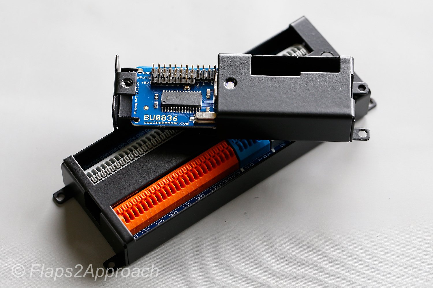
The movement of the flaps lever, prior to calibration must be registered by the Windows Operating System.  This was done using a Leo Bodnar 086-A Joystick interface card.  This card is mounted in the Throttle Interface Module (TIM).    The joystick card, in addition to the flaps lever, also registers several other button and lever movements on the throttle quadrant.  

Final Call

The rebuild has enabled a more reliable and robust system to be installed that has rectified the shortfalls experienced in the earlier system.  The new system works flawlessly.

  • This article displays links to the majot journal posts concerning the 737 throttle: OEM Throttle Quadrant

Acronyms and Glossary

  • OEM - Original Aircraft Manufacture (real aircraft part).

Correcting Lag in ProSim737 Weather Radar

This short article relates only to the ProSim737 avionics suite.

The software that controls the avionics suite enables many features to be displayed on the Primary Flight Display (PFD) and Navigation Display (ND), and it's paramount that the PFD and ND display the best possible rendentation of the avionics that is possible.  Anything less will detract from the simulation experience.

ProSim-AR (the developers of ProSim737) are constantly updating their software to facilitate new features, functionality, and improve on existing functionality within the avionics suite.

One area of improvement recently implimented has been the detail that the terrain and weather (from the weather radar) is displayed on the ND.  

Performance Issue

Although the improvement is welcomed, many enthusiasts have reported performance issues when the terrain, or more specifically, the weather radar is displayed.  The condition usually becomes worse when other functionality, such as waypoints, airports, stations, and data are also selected on the EFIS to display on the ND (in addition to terrain and weather radar).  

The performance spike presents as a stuuter, lag, or pause, and this becomes more evident when the aircraft is climbing or banking; the altitude tape in the PFD stutters, as does the compass rose as it moves to a new course heading.

Attempting to Resolve Lag

ProSim-AR have attempted to resolve the issue of lagging, by releasing an alterative method to how the software interprets and displays the data (Direct2D).  Although the use of Direct2D has been ‘more or less’ resolved the display lag or stutter, other problems have surfaced such as the positioning and clarity of the displayed fonts.

It’s important to realize that the lagging issue is not a direct result from a low performance computer or graphics card.  Although using a high-end computer and graphics card will help to provide the necessary ‘grunt’ to display the data without any lagging.

Possible Solution to Lag

On my simulator set-up, I was using one computer monitor and one instance of ProSim737 (ProSim Display) to display the data on the PFD and ND.  Using this combination, my set-up always exhibited lagging and stuttering.  

Recently, I decided to run one instance of ProSim Display for the PFD and another for the ND, while displaying both the PFD and ND on the same computer monitor.  In other words, I separated the resources that are used to display the PFD and ND.

I was surprised that this combination resolved the lagging problem.  I can now operate the ND with waypoints, airports, stations and data, and change between the weather and terrain display without any major lagging being evident on the altitude tape of the PFD or ND compass rose (assuming the aircraft is climbing and/or banking).

Configuration

Setting up the two instances of ProSim Display to feed directly to one computer screen is straightforward.  However, configuring the position of the PFD and ND so that they are adjacent to each other and can be seen simultaneously can be ‘tricky’.  It does take a little bit of time to set up.

Prior to changing anything, always make a back-up copy of your config file.  This file, amongst other things, contains the last position of your various displays on the computer monitor.  The config file is located with the ProSim Display folder.

Excess Data Display

The ND will often display the words 'Excess Data'.  This message indicates that the ND is not capable of displaying all information.  If you deselect an ND option on the EFIS, the display will usually extinguish.  The display also appears on the the ND in the real aircraft.

The message can be disabled in the ProSim737 Instructor Station.

Final Call and Disclaimer

This simple procedure resolved the issue of display lagging on my simulator, however your ‘mileage’ may differ.  Each computer is unique.

If it doesn’t work, then delete the config file and replace it with the backed-up copy.  This will revert the position of the displays to your earlier set-up.  

At the time of writing this article, I was using ProSim737 Version 219b10 with Lockheed Martin P3d Version 4.4 and 4.5.

Repair Backlighting on Throttle Quadrant

The rear of the First Officer side trim lightplate showing one of the two terminals that the wiring loom connects to

During a recent flight, I noticed that the bulbs that illuminate the backlighting for the trim and flaps lightplate (First Officer side) had failed, however, the backlighting on the Captain-side trim lightplate was illuminated.  My first thought was that the 5 volt bulbs that are integrated into the lightplate had burned out; after all, everything has an end life.

Backlighting - Wiring Loom

The wiring loom that supplies the power for the backlighting enters the throttle quadrant via the front firewall, and initially connects with the trim lightplate and parking brake release light on the Captain-side.  A Y-junction bifurcates the wire loom from the Captain-side to the First Officer side of the quadrant, before it snakes its way along the inside edge of the quadrant firewall to connect with the First Officer side trim lightplate, and then the flaps lightplate.  The wiring loom is attached securely to the inside edge of the throttle casing by screwed cable clamps.

The backlighting for all lightplates is powered by 5 volts and the backlighting on the throttle quadrant is turned on/off/dimmed by the pedestal lighting dimmer knob located on the center pedestal. 

Finding the Problem

Ascertaining whether the bulbs are burned out is uncomplicated, however, assessing the terminals on the rear of each lightplate, and the wiring loom the connects to the lightplates, does involve dismantling part of the throttle quadrant.

The upper section of the throttle quadrant must be dismantled (trim wheels, upper and side panels, and the saw tooth flaps arc).  This enables the inside of throttle quadrant to be inspected more easily with the aid of a torch (lamp/flashlight).  When removing the trim wheels, be especially vigilant not to accidently pull the spline shaft from its mount, as doing so will cause several cogs to fall out of position causing the trim mechanism to be inoperable.

After the lightplates have been removed, but still connected to the wiring loom, a multimeter is used to read the voltage of each respective terminal on the lightplate. If the mutlimeter indicates there is power to the terminals, then the bulbs should illuminate. 

What surprised me when this was done, was that the bulbs worked perfectly. Therefore, it was clear the problem was not bulb, but wire related.

Process of Elimination

The process of elimination is the easiest method to solve problems that may develop in complicated systems.  By reducing the components to their simplest form, a solution can readily be attained.

Alligator wire connects power from Captain-side lightplate to the First Officer lightplate.  Note the frayed outer layer of the white aircraft wire.  The gold colour is a thin layer of gold that acts as a fire retardant should the wiring overheat

If you suspect that the wiring is the problem, and don't have a multi meter, then a quick and fool safe method is to connect an alligator cable from the positive terminal of the Captain-side lightplate to the respective terminal on the First Officer lightplate.  Doing this removes that portion of the wiring harness from the circuit. 

In this scenario, the  bulbs illuminated on both trim lightplates.  As such, the problem was not bulb related, but was associated with the wiring loom.

It must be remembered that the wire used to connect the backlighting in the throttle quadrant is OEM wire.  As such, the age of the wire is the same age as the throttle quadrant.  

Inspecting the wire loom, I noticed that one of the wires that connected to the terminal of the lightplate was severed (cut in two).   I also noted that the original aircraft wires had begun to shed their protective insulation layer. 

Aircraft Wire and Insulation Layers

The high voltage and amperages that travel through aircraft wire can generate considerable heat.  This is why aircraft wire is made to very exacting standards and incorporates several layers of insulation that surround the stranded stainless steel wire.  The use of high-grade stainless steel also provides good strength and resistance to corrosion and oxidation at elevated temperatures.  

The green wire has been severed.  A possible scenario was that the wiring loom had been pulled slightly loose from the throttle chassis, and had become caught in the flaps mechanism.  When the flaps lever is moved, the mechanism can easily crimp (and eventually sever) any wire in its path.  If you observe the white wire you can see the insulation that is shedding

Interestingly, one of the insulating layers is comprised of gold (Au).  The gold acts as an effective fire retardant should the wires overheat.

The breakdown of the upper insulating layer is not a major cause for concern, as a 'shedding' wire still has enough insulation to not arc or short circuit.  However, the wire should be replaced if more than one layer is compromised, or the stainless threads of the wire are visible.

Possible Scenario

When inspecting the wiring loom, I noted that one of the screws that holds the cable clamp to the inside of the throttle casing was loose.  This resulted in part of the wire loom to 'hang' near the flaps arc mechanism.    It is possible that during the throttle’s operational use, the movement and vibration of the aircraft had caused the screw to become loose resulting in the wires hanging down further than normal.  It appears that the wire had been severed, because it became caught in the mechanism of the flaps lever.  

Unlike reproduction throttles, the parts used in an OEM throttle are heavy duty and very solid; they are designed to withstand considerable abuse.  The speedbrake lever, when activated can easily cut a pencil in two, and the repeated movement of the flaps lever, when moved quickly between the teeth of the flaps arc, can easily crimp or flatten a wire.

Rather than try to solder the wires together (soldering stainless wire is difficult) and possibly have the same issue re-occur, I routed the wires from both lightplates (trim and flaps) directly to the 5 volt bus bar located in the center pedestal. 

I could have removed the wire loom completely and replaced it with another loom, however, this would involve having to disassemble the complete upper structure of the throttle quadrant to access the wire loom attachment points on the inside of the throttle casing; something I was not keen to do.

Final Call

OEM parts, although used in a static and simulated environment can have drawbacks.  Apart from age, the repeated movement of mechanical parts and the vibration of the spinning trim wheels, can loosen screws and nuts that otherwise should be securely tightened. 

Acronyms

  • OEM – Original Equipment Manufacturer

  • Wire Loom – Several wires bundled together and attached to a fixed point by some type of clamp

ISFD Knob Fabricated

OEM ISFD (Image copyright Driven Technologies INC)

The Integrated Standby Flight Display (ISFD) is mounted in the stand-by instrument cluster in the Main Instrument Panel (MIP).  The ISFD provides redundancy should the Primary Flight Display (PFD) on the Captain or First Officer fail. 

The ISFD is not a common panel to find second hand, and working units are expensive to purchase.  I don't  have an OEM ISFD, but rather (at least for the moment) use a working virtual image displayed by ProSim737. 

ISFD knob.  Two versions: one replicates the taller NG style while the other is slightly shorter.  Although not functional, they provide a better representation of the plastic knob that previously was installed

Conversion of an OEM unit is possible, however, the unit would need to be fully operational, and  finding a working unit at a reasonable price is unlikely.  ISFDs are expensive and reuse is common.  If a unit does not meet certification standard, it's disposed of because it's broken and cannot be economically repaired.

ISFD Knob

The ISFD knob that came bundled with the MIP I purchased is very mediocre in appearance – in fact it's a piece of plastic that barely looks like a realistic knob.  I purposely have not included an image, as the design would be an embarrassment to the company that produced the MIP.

A friend of mine is a bit of a wizard in making weird things, so I asked him if he could make a knob for me.  He made two knobs – one based on the standard design seen in the Next Generation airframe and the other knob a shorter version of the same type. 

Knob being fabricated on a lathe

Attention to Detail

Attention to detail is important and each knob has the small grub screw and cross hatch design as seen on the OEM knob.  The knobs have been made from aluminum and will be primed and painted the correct colour in the near future.

A 2 axis CNC lathe was used to fabricate the knobs.  The use of a computer lathe enables the measurements of a real knob to be accurately duplicated, in addition to any design characteristic, such as cross hatching or holes to install grub screws.

Differences in Colour, Manufacturer, and Layout in the Center Pedestal

There are several panels that make up the center pedestal, main instrument panel, and overhead in the Boeing 737 aircraft. Most of the panels are required by international law, and a carrier cannot fly if certain panels do not function correctly.

Although the aviation regulations require aircraft to have certain panels, there are panels that are airline specific. These panels are chosen when the aircraft is ordered from Boeing, or they may be installed at a later on. Similar to automobiles, there are a number of manufacturers of aviation panels and each panel, although having identical functionality may differ slightly.

All high-end simulators replicate the panels required by the authorities, and enthusiasts often fixate on a number of supposed issues. Namely:

(i)         The colour of the panel and lightplate;

(ii)        The position of the panel in the center pedestal;

(iii)       The backlighting of the lightplate (bulbs verses LEDs);

(iv)       The manufacturer of the panel, and;

(v)        The aesthetic condition of the lightplate.

Although seemingly important to a cockpit builder, to the casual observer, or indeed to many pilots, these attributes are of little consequence.  Nevertheless, it's understandable to a newcomer that all panels in the 737 Next Generation are identical between all aircraft.

Whilst it's true that all airlines must meet aviation standards for the type of operation they fly, the panel manufacturer and where in the pedestal the panel is located is at the discretion of the airline.  Furthermore, it's not uncommon to observe older style panels mixed with modern panels and to see lightplates that are illuminated by bulbs and LEDs side by side.

Note that some of this information probably pertains more to older Next Generation 737s than to the latest Next Generation released from Boeing.  I use the word 'panel' to denote an avionics module.

Air Alaska 737-700 pedestal.  Note higher than standard position of ACP panels and relocated position of the door lock panel.  Also high mounted position of rudder trim panel

Colour of Lightplates

The official colour shade used by Boeing is Federal Standard 5956 36440 (light gull grey).  However, OEM part manufacturers may use slightly different colour hues.  For example, IPECO use British Standard 381C-632 (dark admiralty grey) and Gables use RAL 7011.  This said, often an airline will 'touch up' a lightplate that is damaged or faded - this introduces a further colour variant. 

For example, a lightplate I acquired from a 737-500 airframe revealed three differing shades of grey beneath the final top coat of paint.  This is not to mention that, depending on the manufacturer of the lightplate, the final coat of paint may be matt, semi-matt or gloss.

From the perspective of an engineer, the colour (and to a certain extent aesthetic condition) is unimportant when replacing a defective part with another.  Time spent in the hanger equates to a loss in revenue by the airline.  Therefore turn-around times are as brief as possible and keeping an aircraft on the ground while procuring the correct shade of Boeing grey does not enter the equation.

Position of Panels in the Center Pedestal

Boeing recommends a more or less standard position for the essential panels in the center pedestal (NAV, COM, ADF, ASP, rudder trim, door lock and panel flood), however, the location of the panels is often altered by the receiving airline, and is to a certain extent is determined by what other panels are installed to the pedestal.  Areas (holes) in the pedestal not used by a panel are covered over with a grey-coloured metal blank.

LEFT:  This photograph of the center pedestal of a Boeing 737-500 was taken in 2016.  The aircraft is a freighter converted from a passenger aircraft.  Apart from the older style ACP panels, note the disparate displays between the NAV and COM radios.  Also note the position of the ADF radios and some of the other panels; they do not conform to what is usually thought of as a standard set-out.  Finally, note the scratches on the pedestal and on some of the panels and lightplates - they hardly look new.

Panels are manufactured by several companies, and often there appearance will differ slightly between manufacturer, although the panel's functionality will be identical.  The airline more often than not chooses which panel is used, and often the decision is biased by the cost of the panel.  Therefore, it's not uncommon to observe several airframes of a similar age with differing panels positioned in different areas of the center pedestal.

Panel Condition

Enthusiasts pride themselves in having a simulator that looks brand new.  However, in the real world a Level D simulator or flight deck rarely looks new after entering service.  Panels can be soiled and paint is chipped and scratched, and depending on age, some lightplates are faded to due to the high UV environment that is present in a flight deck.

So where am I going with this?  Enthusiasts strive to match their panels with those observed in a real airliner, however, more often than not this information comes from photographs distributed by Boeing Corporation, which nearly always depict panels in a standard position, especially in relation to the center pedestal. 

The variables noted by enthusiasts should not cause consternation, as real aircraft show similar variation.  Remember that in the real aircraft, colour, manufacturer, and to a certain extent aesthetic condition is not important - functionality is.

Conversion of OEM CDU - Part Two

OEM CDU operational with ProSim737

In this second article, I will explain how the OEM Control Device Unit (CDU) was converted to enable a SimStack Foundation Board to be installed inside the unit and connected to ProSim737. 

SimStacks are manufactured by Simulator Solutions, which is a Sydney based company in Australia and their foundation boards can be used with ProSim737 and ProSim320 avionics suites. 

This is but one method to convert an OEM item to be used with flight simulator.

This article will mainly address the mechanical conversion of the CDU.  A future article, after flight testing,  will provide a review of SimStacks interface cards.

Conversion

Many of the OEM parts used in the simulator have been converted using Phidget cards, and to a lesser extent Leo Bodnar and PoKeys interface cards.  Phidgets provide a stable platform, despite the disadvantage that they, at time of writing, can only connect via USB to the server computer, and don’t enable every OEM function to be used in ProSim-AR.  The primary advantage of using Phidgets is that they have been used in a wide variety of applications, are inherently stable, and their configuration is well documented.

I decided that, rather than use Phidgets, a different system would be trailed to interface the CDU with ProSim737. 

he SimStack Foundation Board mounted on an angular bracket inside the CDU.  Fortunately there is ample room to mount the board inside the CDU

SimStacks by Simulator Solutions

The conversion of the CDU was done in collaboration with Sydney-based company Simulator Solutions Pty Ltd.  Simulator Solutions use their propriety interface boards called SimStacks to convert OEM parts for use in commercial-grade simulators.

SimStacks is a modular, stackable, and scalable hardware interface that is designed to integrate OEM parts into your simulator with little or no modification.    One of the many advantages in using a SimStack board is that the interface can connect with either the server or client computer via Ethernet (as opposed to Phidgets). 

To date, Simulator Solution’s experience has been predominately with the conversion of B747 parts and Rodney and John (owners) were excited to have the opportunity to evaluate their software on the 737 platform using ProSim737. 

Converting the CDU - Choose Your Poison

There are two main camps when discussing how to convert an OEM part.  The first is to use as much of the original wiring and parts as possible.  The second is to completely ‘gut’ the part and convert it cleanly using an interface that connects seamlessly with the avionics software in use (ProSim-AR).  A third option, although expensive and in many respects ‘experimental’, is to use ARINC 429. 

ARINC 429 is a protocol used in real aircraft to enable panels etc to be connected with the aircraft’s systems, and although it can be used in a simulated environment, it’s not without its shortfalls, in particular, the use of AC power (in contrast to DC power).

To use SimStacks the internal components of the CDU had to be removed, with the  exception of the internal shelf divider and keypad.  In hindsight, the pin-outs of the Canon plugs could have been used, but in doing so a female Canon plug would have been required, and for the use of a couple of pins, the price of a Canon female plug was expensive.

Keypad and Screen

The keypad and screen are the two most important parts of the CDU. 

The keypad forms part of the lightplate.  The backlighting for the keypad is powered by 21 5 Volt incandescent bulbs, strategically located to ensure even backlighting of the keys.

table 1: provides an overview of bulb location, part number and quantity

Like anything, bulbs have a limited left and, although OEM bulbs are renown for their longevity, there is always a chance that some bulbs are broken.  In this case, there were 3 bulbs that needed replacement.

Disassembling and removing the keypad from the main body of the CDU is straightforward; several small Philips head screws hold the keypad in place.  Once the keypad has been removed, any ‘blown’ bulbs can be replaced. 

The most important area is the keypad is what is called the terminus (bus).  Several wires from the keypad travel to the bus and then to the various (now removed) parts in the CDU.  The Simstack Foundation Board is wired to the bus, therefore, care must be taken to not damage these wires between the bus and the keypad. 

737 CL CDU showing older green coloured text displayed on CRT screen

I found that the wires were quite short and needed to be lengthened; this can be done by splicing longer wire to the existing wire.  Although it's possible to replace the wire to the keypad, this would entail re soldering the wires to the various keypad points - a process that requires very exact soldering.

CRT screen showing thick curved glass

CRT and LCD Screen

The Classic CDU from airframes up to the Boeing 737-500 is fitted with a solid glass cathode ray tube (CRT) screen. 

The CRT screen is approximately 2 cm thick, curved in design, and fits snugly within the display frame of the CDU.  Although it’s possible to make this screen operational, the display will be mono-colour (green) and the screen resolution poor.  Therefore, the CRT was replaced with a custom-sized high resolution colour LCD screen.

To replace the CRT screen is not without its challenges.  The first being that the LCD screen is not 2 cm in thickness and will not fit snugly within the curved display recess of the CDU frame.  To rectify this shortfall, a piece of clear glass must be ground to correctly fit within the frame.  This piece of glass replaces the 2 cm thick, curved CRT glass.

Photo showing how the thin LCD screen was secured with tape the glass screen.  Although the process appears rudimentary, it's functional

The thin LCD screen is installed directly behind the clear glass using high density tape.  Commercial grade double-sided sticky tape is the easiest method, but it is rudimentary.  The reason that tape is used, is that should the screen fail, it’s easy to remove the tape, install a replacement screen, and then tape the screen in place.

During the design phase, it was thought that the thick piece of glass would cause a refraction problem.  However, although the theory suggests refraction will occur, the practical application has been such that any refraction is not readily noticeable.

Installing the SimStacks Foundation Board and Screen Controller Card

To enable the CDU to operate, four items need to be mounted inside the CDU.

(i)   The generic Interface card that controls the LCD screen;

(ii)   The LCD screen controller (buttons that control brightness, contrast, etc);

(iii)  The SimStack Foundation Board; and,

(iv)  The wiring to connect the keyboard to the Foundation Board.

Fortunately, there is ample room in the cavernous interior of the CDU to fit these items. 

The SimStack Foundation Board is mounted on an angular metal bracket that is attached directly to the bottom of the CDU, while the LCD interface card has been installed on the upper shelf along with the screen controller.  A ribbon cable connects the LCD screen to the interface card while a standard VGA cable connects the LCD screen to the client computer and Ethernet switch. 

The SimStack Foundation Board is Ethernet ready and requires a standard Ethernet cable (CAT 6) to connect from the card to an Ethernet switch (located behind the MIP).  In addition to the Ethernet  and VGA cable, six power wires leave the CDU via the rear of the casing; four from the SimStack Foundation Board (5 and 12 volts +-) and two from the keypad (5 volts +-) to control the backlighting.

The specialist switch and wiring (Ethernet, power and VGA cables) extruding from the rear of the CDU

Specialist Switch and Power Supply

A standard two-way toggle switch is mounted to the rear of the CDU casing. 

This switch is used to control whether the LCD screen, used in the CDU, is always on, or is only turned on when ProSim-AR is activated.

To operate the CDU requires a 5 and 12 volt power supply.  The backlighting of the keypad is powered by 5 volts while the SimStack Foundation Board and CDU operation require 12 volts.

Backlight Dimming (keypad)

To enable the CDU keypad to be dimmed, the 5 volt wires are connected to a dedicated 5 volt Busbar located in the center pedestal.  This Busbar is used to connect the backlighting from all OEM panels.  The Busbar is then connected to the panel knob on the center pedestal.  The ability to turn the backlighting on and off is controlled by opening or closing a 12 volt relay (attached in line between the panel knob and Busbar).  Dimming is controlled by a dimmer circuit (see earlier article).

Installing the OEM CDU to Flight Deck Solutions MIP

It can be challenging attempting to install OEM panels, gauges and other items to a reproduction Main Instrument Panel (MIP).  Unfortunately, no matter what the manufacturer states, many MIPS do not comply with real world measurements.  

Before and after photograph of the FDS CDU bay showing the small flange from the shelf that needed to be trimmed to enable the CDU to slide into the bay recess.  A small notch was made at the corner to facilitate the safe routing of the wires used to enable the Lights Test

The MIP skeleton is manufactured by Flight Deck Solutions (FDS) and the CDU bay, although fitted with OEM DZUS rails, is designed to fit FDS’s propriety CDU unit (MX Pro) and not an OEM unit. 

The casing for the OEM CDU is much longer than the FDS CDU and measures 20 cm in length.

The FDS MIP design is such that the aluminum shelf (used by FDS to mount various interface cards) protrudes slightly into the rear of the CDU bay.  This protrusion stops the OEM casing from sliding neatly into the bay to its fullest extent.  To enable the CDU to slide into the CDU bay, the shelf must be ‘trimmed’.

To trim the metal away from the shelf, a small metal saw was used, and although an easy task, care must be taken not to ‘saw away’ too much metal.  Once the piece of offending aluminum is removed, the CDU slides perfectly into the bay, to be secured by DZUS fasteners to the DZUS rail.

Functionality and Operation

The CDU is not intelligent; it’s basically a glorified keyboard that must be interfaced with ProSim-AR to enable the CDU to function correctly.  The fonts and colour of the fonts is generated by the avionics suite (in this case ProSim-AR, but arguably it could also be Sim Avionics or Project Magenta). 

To enable communication between the avionics suite and the SimStack Foundation Board, proprietary software must be installed.  This software has been developed by Simulator Solutions.

SimStack Software (simswitch)

Screen grab showing SimSwitch software User Interface.  SimSwitch is standalone once the initial configuration has been completed.  The software can be configured to open in minimised mode via a batch file

To enable communication between the Foundation Board and ProSim737, propriety software, called SimSwitch must be installed to the computer that has the CDU connected. 

SimSwitch is a JAR executable file, that when configured with the correct static IP address and port numbers, provides communication between ProSim-AR (on the server computer) and the network (clients).  The switch must be opened for communication to occur between the Foundation Board, SimSwitch and ProSim737.  The jar file can easily be included into a batch file (with timer command) for automatic loading when flight simulator is used.

When opened, SimSwitch displays the User Interface.  The User Interface displays all OEM panels that have been connected using a SimStacks, can be used to monitor connected panels, and can display debugging information (if required).

Independent Operation

The Captain and First Officer CDUs are not cloned (although this is easy to do), but operate as separate units.  This is identical to the operation in the real aircraft, whereby the Captain and First Officer are responsible for specific tasks when inputting the information into the CDU.

First Officer CDU

The First Officer CDU will be converted using a similar technique, with the exception that this unit will be converted more ‘cleanly’.  Rather than use an angled plate on which to attach the SimStacks Foundation Board, a solid aluminum plate will be used.  The LCD screen controller card will also be attached to the rear of the LCD screen.  Finally, to enable fast and easy removal of the CDU, the connection of the Ethernet cable will be outside of the unit.

Additional Information

SoarByWire (another enthusiast) has written an excellent article dealing with interfacing SimStacks.

Below is a short video demonstrating the operation of the OEM CDU using ProSim737.

Main points to note in the video are:

  • Heavy duty tactile keys.

  • The definite click that is heard when depressing a key.

  • The solid keypad (the keys do not wobble about in their sockets).

  • Although subjective, the appearance of the OEM CDU looks more aesthetically pleasing that a reproduction unit.


Final Call

The conversion has been successful and, when connected with ProSim737 via SimSwitch, all the functions available in the CDU work correctly.

Glossary

  • ARINC 429 –  A standard used to  address data communications between avionics components.  The most widely used  standard is an avionics data bus.  ARINC 429 enables a single transmitter to communicate data to up to 20 receivers over a single bus.

  • Standalone – Two meanings.  Operation does not require an interface card to be mounted outside of the panel/part; and, In relation to software, the executable file (.exe) does not need to be installed to C Drive, but can be executed from any folder or the desktop.

  • Updated for clarity and information 12 June 2020.

Troubleshooting Power Management Settings and Solving USB Disconnects

High-speed 5 volt powered USB hub.  This hub resides in the Throttle Interface Module (TIM).  Note ferrite choke

Remember when all that was required to run flight simulator was one display monitor, joystick and a keyboard – those days are long gone.   

Depending upon the level of system complexity, a flight simulator may require a dozen or more ports to connect peripheral items to a server or client computer (s).  Historically, connection of peripherals has been via USB.  

USB is an acronym for Universal Serial Bus and, generally speaking, if only a few peripherals are attached to a computer, there usually is not a problem with communication between the computer and the attached device.  However, as interface cards and peripherals become more complicated and numerous, there is a propensity for disconnects to occur more frequently.  A USB disconnect usually announces itself by the sound card playing the ‘ding-dong’ sound as the peripheral disconnects itself from the computer.

Guidelines (golden rules)

There are several ‘golden rules’ to remember when using USB.

(i)      Try and keep all USB cables as short as possible;

(ii)     Do not join USB cables together;

(iii)    Always use quality USB cables with quality connectors;

(iv)    Do not ‘kink’ the USB cable or wrap the cable so tightly that the wires are at a 90-degree angle;

(v)     Do not lie USB cables beside one another so they are touching, but maintain some space between them;

(vi)     Use a USB cable fitted with noise limiting nodes (NLN);

(vii)    Use a USB cable/port that is rated at the highest output (USB 3 or above);

(viii)   For multi USB connections use a quality powered USB hub; and,

(ix)     Try to maintain space between USB cables and power cables.

Ferrite choke on USB cable

Noise Limiting Node (NLN)

A noise limiting node (NLN), also known as a 'ferrite choke' is a small cylindrical node that sits at each end of a USB cable.  Briefly explained the nodes are made from a solid ball of ferrite which is magnetic and therefore quite heavy.

The purpose of the NLN is to stop electromagnetic interference (EMI) transferring from the peripheral to the computer.  EMI can be produced from any number of peripheral items and a USB cable running between the peripheral and the computer acts as an antenna, picking up and transmitting EMI current.  The current can, but not necessarily always, cause havoc with either the operation of the peripheral or the computer itself.  

Adding USB Ports

As the number of add-on peripherals increase, the number of available ports falls short and additional USB ports need to be added to the computer.  Additional ports can easily be added to a computer via a PCE card which enables (on average) an additional 4 USB ports to be added to your computer.  A PCI card is attached to your motherboard.

Power Requirements

One of the main reasons that USB disconnects occur, relates to the power that is available to the computer’s USB port.  Often the power requirements of the device will be greater than that provided to the USB port; this causes a disconnect.  Additionally, depending upon your computer, it is not uncommon for power to fluctuate between USB ports as the computer’s motherboard directs power to various processes.

Depending upon how your system is set-up, when several devices 'come on line' a minor spike can be generated.  Often, this spike can momentarily exceed the amperage rating of the USB port.  This can cause a disconnect to occur.

It’s important to understand that not all USB ports are made identical.  In general, the ports on the rear of the computer are part of the computer’s motherboard; these ports are rated as high power ports.  However, USB ports that are not part of the motherboard, and usually located on the front of the computer may not receive the same power rating.  

Often a supply company will provide a computer will a dozen or so USB ports, however, to save money will choose to use what is called a ‘front panel USB header’ which has a small piece of circuitry that acts as a hub.  In this case, the power to the front panel USB is reduced.  Furthermore, it is probable that these ports may not be USB 3 and if used for a high-demand peripheral will cause a disconnects to occur.

USB Hubs

Another strong recommendation is to use a high quality powered USB hub rather than connecting several USB cables directly to a computer.  A powered hub should be used rather than an unpowered hub as the former provides its own direct power source which is usually rated at a higher amperage than the computer’s USB port.  

The interface modules that form the core of my simulation system have one or two powered hubs installed to the module.  The interface cards are then connected by very short USB cables to the hub.  A high quality USB cable (with a NLN) then connects the interface module directly to the computer.

Recommended USB Hubs:

  • The USB hubs I use are Belkin powered 5 and 7 port USB hubs (Belkin F5U237-C). The C refers to the connector on he USB cable.

Screen grab of Windows 7 PMS.  Windows 10 is similar

Windows Power Management Settings (PMS)

Not all USB peripherals will be required at all times.  Often a device will not need to communicate with the computer until something is required – such as a change to a radio frequency, an input from the control column or a key press to the MCP or CDU.

Windows has a nasty habit of ‘putting to sleep’ a USB connection that is not being used.  It does this to save power.  It is very imperative that you ensure that all power saving modes are turned off with regard to USB.  

To do this open your control panel and search for device manager.  Scroll down until you find Universal Serial Bus.  Under this tab you will find all the USB ports that you have attached to your computer.  Open each in turn and check the power management settings and ensure they are turned off.

Troubleshooting USB Disconnects

It is paramount to try and discover which peripheral is causing the disconnect.  The easiest way to troubleshoot a disconnect issue is to remove ALL the USB cables from the computer, and then one by one re-connect the cables to the allocated port and test.  Make sure you switch your computer off and on as you add each of the cables in turn.  Hopefully, you will eventually discover which cable/device is causing the issue.  The problem device will generate ‘ding dong’ if a secure connection is not possible.

If USB disconnects continue, try swapping the cables between different USB ports on the computer.  The disconnect issue maybe caused by the USB port/cable combination you are using.  As mentioned, not all USB ports have the same amount of power/amps available to them. 

Try to place peripherals that require minimal power, such as a mouse or keyboard, on lower-powered USB ports, and place more energy-requiring peripherals on powered hubs; perhaps only a few devices on the one hub.  Doing this will ensure that the hub will always have enough power (amps) to power the devices attached (cancelling out possible spikes as discussed above).  

A potential problem can be located with the USB cable, cleanliness and tightness of USB connections (including any USB hub), and loose wiring (especially if connectors have been used to secure the wiring).

Clean the USB connections with a quality cleaner to ensure cleanliness and make sure the USB connectors are tight.  If the connectors need tightening, this can easily be done by pushing the small tabs inward on the female USB connection.

Final Call

Hopefully, if you apply the above-mentioned suggestions USB disconnects will cease.  However, you will eventually reach the limit of USB capability, and at this point the use of Ethernet should be investigated to augment, or to replace the reliance on USB.

This article is but a primer.  I am not an IT expert and welcome any comments.