B737 Aural Warning Module (AWM) Installed and Operational
/front of oem aural warning module
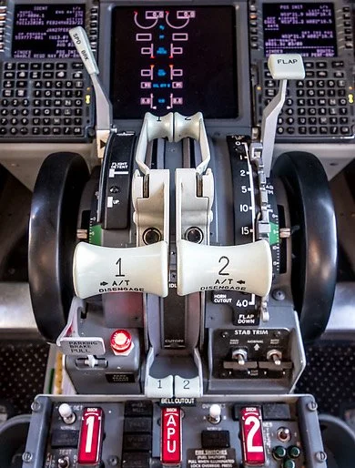
One of the recent upgrades to the simulator has been the installation of an Aural Warning Module (AWM). This module resides on the first officer side of the flight deck and is attached to the forward bulkhead of the Main Instrument Panel directly beside the throttle quadrant. The module replaces four of the computer-synthesised warnings with the OEM counterparts.
The purpose of the module is straightforward; to provide a fail-safe mechanical device that delivers loud, clear and concise tones and bells to indicate to the flight crew that major problem or configuration issue exists. The aural alarms activate in unison with warning lights that are located on the forward overhead panel, fire suppression panel and on the glare shield of the Main Instrument Panel (six pack annunciators and master fire warning (bell cutout) and master caution buttons).
What's in the Grey Box
The aural warning box contains three mechanical devices capable of delivering four aural warnings:
(i) The fire bell;
(ii) The clacker; and,
(iii) The horn (double purpose that activates either in a continuous or intermittent tone).
The fire bell rings when any number of events relating to a fire on the aircraft occurs. The fire bell can be silenced by either pushing the master fire warning button located on the glare shield or bell cutout switch located on the fire suppression panel. I will be discussing at length the fire suppression panel in a future post; therefore, will not discuss the various scenarios that the fire bell operates.
The overspeeed clacker sounds when the aircraft exceeds the maximum allowable airspeed (Vmo /Mno). The warning clacker can only be silenced by reducing your airspeed below Vmo/Mno.
The intermittent horn is an aural cue for the takeoff configuration alert. The horn will sound when a configuration problem exists with the aircraft. For example, advancing the throttles with the parking break set or the flaps not set.
When the horn is activated a takeoff config warning light (in red) illuminates on the left forward overhead panel. Deactivation of the alarm is by retarding the throttle levers to idle and then configuring the aircraft correctly.
The continuous horn is activated when specific flight conditions are met. The following are the main scenarios that activate this alarm.
The aircraft is below 800 feet radio altitude with flaps set from UP to flaps 10 with either throttle thrust lever set between idle and 20 degrees forward of idle.
The aircraft descends below 200 feet radio altitude (any configuration)
The aircraft has flaps set 15 through 25 with either throttle thrust lever set between idle and 20 degrees forward of idle.
Flaps 15 is selected without the landing gear being in the down position.
The aircraft has flaps set greater than flaps 25.
The aircraft’s landing gear is not extended.
Silencing the Continuous Tone Horn
The horn can be silenced by depressing the horn cutout switch located on the throttle quadrant; however, if the aircraft descends below 200 feet radio altitude, or the flaps are extended greater than Flaps 15 (without landing gear extended), the horn cutout switch will not silence the horn.
Lowering the landing gear or ascending to higher altitude will silence and reset the horn.
Inside the AWM: horn, clacker and bell. The small box houses basic circuitry
OEM
The grey box is not an OEM part; however, is similar to the module used in the 800 series with the exception of a toggle switch located on the upper part of the unit (the toggle switch is used by maintenance). The box was replicated (using vacuform technology) to the identical measurements of the OEM counterpart. The replica box will be replaced when and if I find a 800 series OEM part.
The mechanical tones and bell have been acquired from a Boeing 737-200 series aircraft and retrofitted into the module.
In time as OEM NG AWM will be procured.
Difference Between Classic Series and NG Aural Warning Modules
The AWM for the classic series (300, 400, 500) and NG are different. The 500 is closest to the NG, however, was a transition product.
Earlier AWM were analogue and used circuits to generate (synthesize various sounds), such as chimes, navigation tunes, etc). These AWM used mechanical devices to generate the mechanical sounds such as the horn and fire bell.
The NG AWM is 100% digital and has no physical mechanical devices to generate sound. This said, apparently some earlier NG AWM still include the mechanical fire bell.
The 500 series AWM was transitional between analogue and digital.
The Next Generation AWM has a maintenance toggle at the upper part of the unit. This can be used by maintenance to check the unit and to alter the volume. However, it’s not possible to alter the volume of an individual sound – adjust one sound’s volume and they all either increase or decrease in volume relative to each other (this is what the engineer told me). It’s not possible for pilot’s, using the toggle, to alter the volume or to select what sounds they hear.
Table 1: Excerpt from Boeing maintenance manual explaining conditions necessary for operation

Conversion
The aural tones are mechanical and not software generated. To interface the warnings with ProSim737 a Phidget 0/0/4 card has been used. This card is located within the SIM interface module (SIM) and is connected to the aural warning module by a custom wired VGA cable. The relays on the Phidget card are triggered when a specific condition, based on the offsets set within the avionics software, are met.
Authenticity and Volume
Although FSX, ProSim737, Sim Avionics and many other avionics suites include aural warnings within their package, the clarity and volume in sound produced by a mechanical device surpasses that of a computer generated sound.
"A word of warning". The horns and bell are loud – very loud… They are loud for a reason – to annoy a flight crew so that will not ignore the "urgency" of the alarm. The first time the fire bell sounded during testing made me jump out of my skin! It also activated the “yell” button on my wife…
The devices do not have a volume control. To quieten the aural warnings for “inside” simulation use, I’ve installed foam around the mechanical devices and bell. This has been successful in lowering the volume by around 60%.
Below is a short video showing the Aural Warning Module and its various sounds (turn volume up).