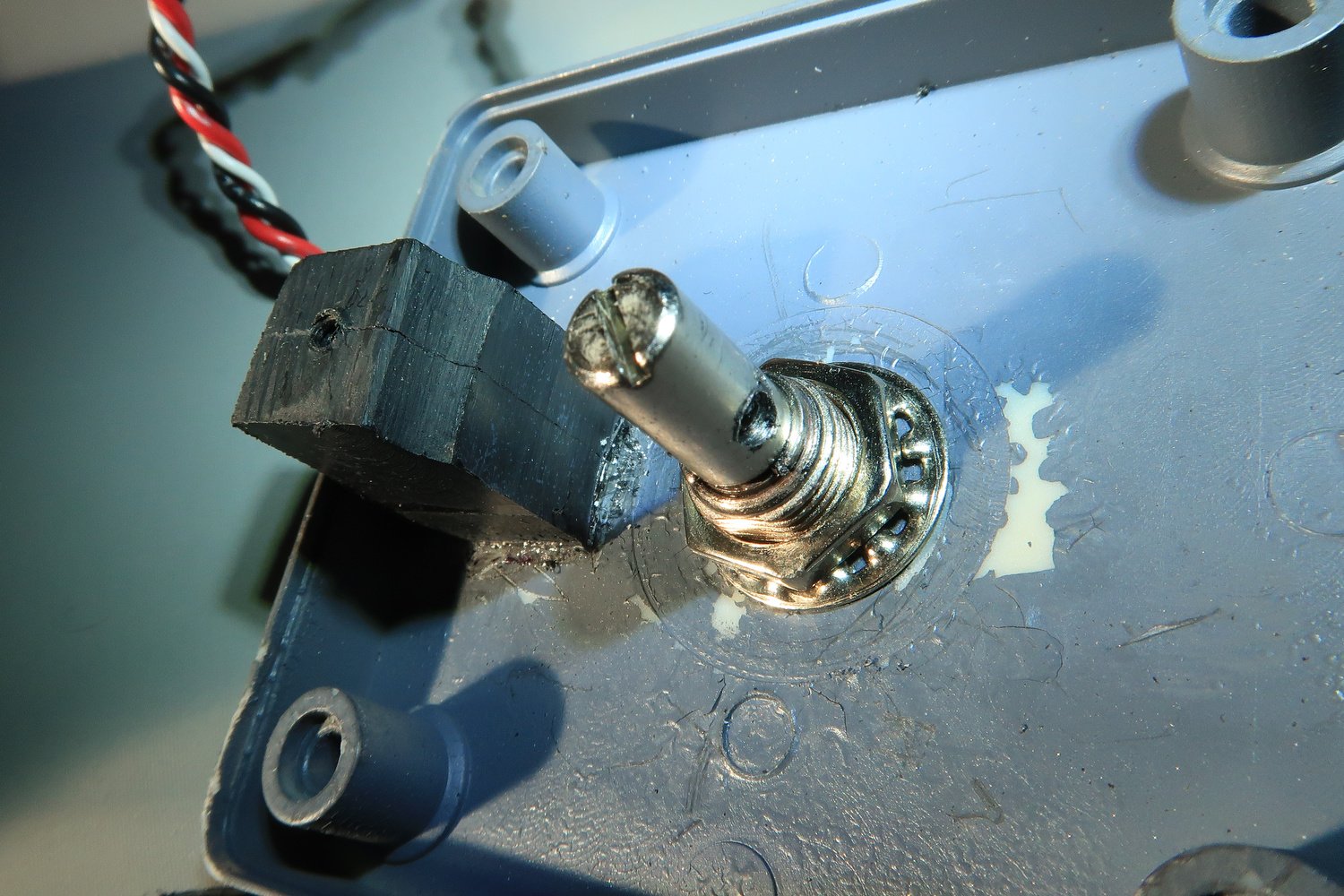
Commercial Rotary-String Potentiometer Review

Commercial Rotary-String Potentiometer Review

Recently, whilst on a final approach I heard a ‘twang’ followed by loss of aileron control.  I knew immediately what had happened; the tensioned stainless steel string from the string potentiometer had snapped and the wire had retracted into the mechanism. 

Read More

Fabricating a String Potentiometer

Bespoke string potentiometer

String potentiometers are fast becoming the mainstay for those wanting to obtain accurate outputs when a lever is moved, such as the: ailerons, elevators, rudder, flaps, speedbrake, or thrust levers in the throttle quadrant.  This is because the slightest movement of a the string is registered by the potentiometer.

While commercial made string potentiometers can be purchased, they are not inexpensive, and if used will deliver an order of accuracy that isn’t necessary for the assigned tasks.

In the example discussed I I am not using a commercial string potentiometer.  Rather, a standard Bourne 3500-3501 rotary potentiometer has been adapted to use a string.

Requirements

You will need the following items:

  1. Bourne rotary potentiometer;

  2. Plastic housing box;

  3. 6 screws (to secure box lid and to fasten spool);

  4. One nut and washer (to secure potentiometer to box)

  5. A retractable spring-loaded spool and stainless steel ot nylon string;

  6. A cylindrical piece if moulded ABS plastic (or wood); and,

  7. A small dog leash type clip or other fastening device (not pictured).

It’s best to use a CNC machine to fabricate the correctly shaped box, however, any box can be used.  Boxes can be purchased from electronic shops that are used as a housing for interface cards.  These are suitable.

It’s difficult to document exactly how the process is done, but by carefully studying the pictures, you should be able to replicate the process.

Fabrication

  1. Make a small hole in the side of the box for the string.  Ensure the hole enables the string to have some lateral movement.  You may need to attach some type of protection to the inside or outside of the hole so that the string doesn’t rub the plastic.  I have used a soft piece of plastic for this task (Figure 1).  Equally suitable is piece of cork (wine bottle)

  2. Drill a circular hole in the top of the box to enable the shaft from the potentiometer to be inserted.  Secure the shaft with a nut and washer (Figure 2).  The main body of the potentiometer will be outside the box.

  3. Glue a piece of solid ABS plastic (or wood) to the lid of the box.  Make a small drill hole that enables a screw to be attached.  This screw is used to help secure the retractable spool (Figure 2, 4 & 6).

  4. You must fabricate, from a piece of ABS plastic or similar, a cylindrical attachment that is glued to the retractable spring-loaded spool.  This piece if plastic must a hole drilled that is the same circumference as the shard of the potentiometer (Figure 3).

  5. The retractable spring-loaded spool is glued to the bottom of the box in direct line with the shaft of the potentiometer.  The shaft must align with the hole in the spool (Figure 1).

  6. Drill a small hole into the side of the shaft of the potentiometer and the retractable spool.  The hole should be large enough to enable a small screw to secure the retractable spring-loaded spool to the shaft.  This is done to stop the spool from freely spooling.  When it’s secured, the string when pulled in or out will turn the shaft of the potentiometer (Figure 2, 3 & 6).

  7. When everything is complete, the string should move the shaft of the potentiometer as it is pulled out of the retractable spring-loaded spool.  To secure the spring to the control device, a small clip can be used which is attached to the end of the string.  I have used a small dog leash style clip, but any clip will work.

Photographs

The fabrication as seen in the gallery photographs appear quite rough.  This is because the example photographed was a prototype.  If you are carefully, work methodically, and have an eye for detail, then there is no reason why the end product will not look semi-professional.


Throttle Quadrant Rebuild - Flaps Lever Uses String Potentiometer

Flaps lever set to Flaps 30.  The throttle quadrant is from a Boeing 737-500 airframe. The flaps lever arc is the curved piece of aluminium that has has cut-out notches that reflect the various flap positions.  It was beneath this arc that micro-buttons had been installed

There are several ways to enable the flaps lever to register a particular flaps détente when the flaps lever is moved to that position on the flaps arc.

In the earlier conversion, the way I had chosen worked reasonably well.  However, with constant use several inherent problems began to develop.

In this article, we'll examine the new system.  But before going further, I'll briefly explain the method that was previously used.

Overview of Previously Used System

In the earlier conversion, nine (9) micro-buttons were used to register the positions of the flaps lever when it was moved (Flaps UP to Flaps 40). 

The micro-buttons were attached to a half moon shaped piece of fabricated aluminium.  This was mounted beneath the flaps lever arc and attached to the quadrant.  Each micro-button was then connected to an input on a PoKeys 55 interface card.  Each input corresponded to an output.

Calibration was straightforward as each micro-button corresponded to a specific flaps position.

Problems

The system operated reasonably well, however, there were some problems which proved the system to be unreliable.  Namely:

(i)    The vertical and lateral movement of the chain located in the OEM throttle quadrant interferred with the micro-buttons when the trim was engaged; and,

(ii)  The unreliability of the PoKeys 55 interface card to maintain an accurate connection with the micro-buttons.

Movement of OEM Chain

The chain, which is similar in appearance to a heavy duty bicycle chain, connects between two of the main cogs in the throttle quadrant.  When the aircraft is trimmed and the trim wheels rotate, the chain revolves around the cogs.  When the chain rotates there is considerable vertical and some lateral movement of the chain, and it was this movement that caused three micro-buttons to be damaged; the chain rubbed across the bottom section of the micro-buttons, and with time the affected buttons became unresponsive.

First Officer side of a disassembled throttle quadrant  (prior to cleaning and conversion).  The large notched cog is easily seen and it's around this cog that the OEM chain rotates (the chain has been removed)

It took some time to notice this problem, as the chain only rotates when the trim buttons are used, and the micro-buttons affected were primarily those that corresponded to Flaps 5, 10 and 15.  The chain would only rub the three micro-buttons in question when the flap lever was being set to Flaps 5, 10 or 15 and only when the trim was simultaneously engaged.

The cog and chain resides immediately beneath the flaps arc (removed, but is attached to where you can see the four screws in the picture). 

Although there appears to be quite a bit of head- space between the cog and the position where the flaps arc is fitted, the space available is minimal.  Micro-buttons are small, but the structure that the button sits is larger, and it was this structure that was damaged by the movement of the chain (click to enlarge).

An obvious solution to this problem would be to move the chain slightly off center by creating an offset, or to fabricate a protective sleeve to protect the micro-buttons from the movement of the chain.     However, the design became complicated and a simpler solution was sought.

Replacement System

Important criteria when designing a new system is: accuracy, ease of installation, calibration, and maintenance.  Another important criteria is to use the KIS system.  KIS is an acronym used in the Australian military meaning Keep It Simple.

The upgraded system has improved reliability and has made several features used in the earlier system redundant.  These features, such as the QAMP (Quick Access Mounting Plate) in which linear potentiometers were installed, have been removed.

String Potentiometer Replaces Micro-buttons

Single-string potentiometer enables accurate calibration of flaps UP to flaps 40.  The potentiometer is mounted on a customised bracket screwed to the First Officer side of the throttle quadrant superstructure.  The terminal block in the image is part of the stab trim wheel system

A Bourne single-string potentiometer replaced the micro-buttons and previously used linear potentiometers.  The string potentiometer is mounted to a custom-designed bracket on the First Officer side of the throttle quadrant.  The bracket has been fabricated from heavy duty plastic.

A string potentiometer was selected ahead of a linear potentiometer because the former is not limited in throw; all the flap détentes can be registered from flaps UP through to flaps 40.  This is not usually possible with a linear potentiometer because the throw of the potentiometer is not large enough to cater to the full movement of the flaps lever along the arc.

A 'string' is also very sensitive to movement, and any movement of the string (in or out) can be accurately registered.

Another advantage, is that it's not overly important where the potentiometer is mounted, as the string can move across a wide arc, whereas a linear potentiometer requires a straight direction of pull-travel.

Finally, the string potentiometer is a closed unit.  This factor is important as calibration issues often result from dust and grime settling on the potentiometer.  A closed unit for the most part is maintenance free.

The end of the potentiometer string is attached to the lower section of the flaps lever.  As the flaps lever moves along the arc, the string moves in and out of the potentiometer. 

The ProSim737 software has the capability to calibrate the various flap détentes.  Therefore, calibration using FSUIPC is not required.  However, if ProSim737 is not used, then FSUIPC will be needed to calibrate the flap détente positions.

Advantages

Apart from the ease of calibration, increased accuracy, and repeatability that using a string potentiometer brings, two other advantages in using the new system is not having to use a Pokeys 55 card or micro-buttons.

Unreliability of PoKeys 55 Interface Card

The PoKeys card, for whatever reason, wasn't reliable in the previous system.  There were the odd USB disconnects and the card was unable to maintain (with accuracy and repeatability) the position set by the micro-buttons.

I initially replaced the PoKeys card, believing the card to be damaged, however, the replacement card behaved in a similar manner.  Reading the Internet I learned that several other people, who also use ProSim737 as their avionics suite, have had similar problems.

Micro-buttons can and do fail, and replacing one or more micro-buttons beneath the flaps arc is a time-consuming process.  This is because the upper section of the throttle quadrant must be completely dismantled and the trim wheels removed to enable access to the flaps arc.

Registering the Movement of the Flaps Lever in Windows

The movement of the flaps lever, prior to calibration must be registered by the Windows Operating System.  This was done using a Leo Bodnar 086-A Joystick interface card.  This card is mounted in the Throttle Interface Module (TIM).    The joystick card, in addition to the flaps lever, also registers several other button and lever movements on the throttle quadrant.  

Final Call

The rebuild has enabled a more reliable and robust system to be installed that has rectified the shortfalls experienced in the earlier system.  The new system works flawlessly.

  • This article displays links to the majot journal posts concerning the 737 throttle: OEM Throttle Quadrant

Acronyms and Glossary

  • OEM - Original Aircraft Manufacture (real aircraft part).

Throttle Quadrant Rebuild - Clutch, Motors, and Potentiometers

Captain-side of throttle quadrant showing an overview of the new design.  The clutch assembly, motors, and  string potentiometer can be seen, in addition to a portion of the revised parking brake mechanism

An earlier article, Throttle Quadrant Rebuild – Evolution Has Led to Major Changes has outlined the main changes that have been made to the throttle quadrant during the rebuild process. 

This article will add detail and explain the decision making process behind the changes and the advantages they provide.  As such, a very brief overview of the earlier system will be made followed by an examination of the replacement system.

Limitation

It is not my intent to become bogged down in infinite detail; this would only serve to make the posts very long, complicated and difficult to understand, as the conversion of a throttle unit is not simplistic.

This said, the provided information should be enough to enable you to assimilate ideas that can be used in your project.  I hope you understand the reasoning for this decision.

The process of documenting the throttle quadrant rebuild will be recorded in a number of articles.  In his article I will discuss the clutch assembly, motors, and potentiometers. 

Why Rebuild The Throttle Quadrant

Put bluntly, the earlier conversion had several problems; there were shortfalls that needed improvement, and when work commenced to rectify these problems, it became apparent that it would be easier to begin again rather than retrofit. Moreover, the alterations spurred the design and development of two additional interface modules that control how the throttle quadrant was to be connected with the simulator.

TIM houses the interface cards responsible for the throttle operation while the TCM provides a communication gateway between TIM and the throttle.

Motor and Clutch Assembly - Poor Design (in previous conversion)

The previous throttle conversion used an inexpensive 12 volt motor to power the thrust lever handles forward and aft.  Prior to being used in the simulator, the motors were used to power electric automobile windows.  To move the thrust lever handles, an automobile fan belt was used to connect to a home-made clutch assembly.

This system was sourly lacking in that the fan belt continually slipped.  Likewise, the nut on the clutch assembly, designed to loosen or tighten the control on the fan belt, was either too tight or too loose - a happy medium was not possible.   Furthermore, the operation of the throttle caused the clutch nut to continually become loose requiring frequent adjustment.

The 12 volt motors, although suitable, were not designed to entertain the precision needed to synchronize the movement of the thrust levers; they were designed to push a window either up or down at a predefined speed on an automobile.

The torque produced from these motors was too great, and the physical backlash when the drive shaft moved was unacceptable.  The backlash transferred to the thrust levers causing the levers to jerk (jump) when the automation took control (google motor backlash).

This system was removed from the throttle.  Its replacement incorporated two commercial motors professionally attached to a clutch system using slipper clutches.

Close up image of the aluminium bar and ninety degree flange attachment.  The long-threaded screw connects with the tail of the respective thrust lever handle. An identical attachment at the end of the screw connects the screw to the large cog wheel that the thrust lever handles are attached

Clutch Assembly, Connection Bars and Slipper Clutches - New Design

Mounted to the floor of the throttle quadrant are two clutch assemblies (mounted beside each other) – one clutch assembly controls the Captain-side thrust lever handle while the other controls the First officer-side. 

Each assembly connects to the drive shaft of a respective motor and includes in its design a slipper clutch.  Each clutch assembly then connects to the respective thrust lever handle.  A wiring lumen connects the clutch assembly with each motor and a dedicated 12 volt power supply (mounted forward of the throttle quadrant).  See above image.

Connection Bars

diagram 1: crossection and a cut-away of a slipper clutch

To connect each clutch assembly to the respective thrust lever handle, two pieces of aluminium bar were engineered to fit over and attach to the shaft of each clutch assembly. 

Each metal bar connects to one of two long-threaded screws, which in turn connect directly with the tail of each thrust lever handle mounted to the main cog wheel in the throttle quadrant. 

Slipper Clutches

close up of slipper clutch showing precision ball bearings

A slipper clutch is a small mechanical device made from tempered steel, brass and aluminum.  The clutch consists of tensioned springs sandwiched between brass plates and interfaced with stainless-steel bearings.  The bearings enable ease of movement and ensure a long trouble-free life.

The adjustable springs are used to maintain constant pressure on the friction plates assuring constant torque is always applied to the clutch.  This controls any intermittent, continuous or overload slip.

A major advantage, other than their small size, is the ease at which the slipper clutches can be sandwiched into a clutch assembly.

Anatomy and Key Advantages of a Slipper Clutch

A number of manufacturers produce slipper clutches that are specific to a particular industry application, and while it's possible that a particular clutch will suit the purpose required, it's probably a better idea to have a slipper clutch engineered that is specific to your application. 

The benefit of having a clutch engineered is that you do not have to redesign the drive mechanism used with the clutch motors.

Key advantages in using slipper clutches are:

  • Variable torque;

  • Long life (on average 30 million cycles with torque applied);

  • Consistent, smooth and reliable operation with no lubrication required;

  • Bi-directional rotation; and,

  • Compact size.

The clutch assembly as seen from the First Officer side of the throttle quadrant.  Note the slipper clutch that is sandwiched between the assembly and the connection rods.  Each thrust lever handle has a dedicated motor, slipper clutch and connection rod.  The motor that powers the F/O side can be seen in the foreground

Clutch Motors

The two 12 Volt commercial-grade motors that provide the torque to drive the clutch assembly and movement of the thrust lever handles, have been specifically designed to be used with drives that incorporate slipper clutches.

In the real world, these motors are used in the railway and marine industry to drive high speed components.  As such, their design and build quality is excellent.

Each motor is manufactured from stainless steel parts and has a gearhead actuator that enables the motor to be operated in either forward or reverse.  Although the torque generated by the motor (18Nm stall torque) exceeds that required to move the thrust lever handles forward and aft, the high quality design of the motor removes all the backlash evident when using other commercial-grade motors.  The end result is an extraordinary smooth, and consistent operation when the thrust lever handles move.

A further benefit using this type of motor is its size.  Each motor can easily be mounted to the floor of the throttle quadrant; one motor on the Captain-side and the second motor on the First Officer-side.  This enables a more streamlined build without using the traditional approach of mounting the motors on the forward firewall of the throttle quadrant.

captain-side 12 Volt motor, wiring lumen and dual string potentiometer that control thrust levers

String Potentiometers - Thrust Levers 1/2

Two Bourne dual-string potentiometers have been mounted in the aft section of the throttle unit.  The two potentiometers are used to accurately calibrate the position of each thrust lever handle to a defined %N1 value.  The potentiometers are also used to calibrate differential reverse thrust.

The benefit of using Bourne potentiometers is that they are designed and constructed to military specification, are very durable, and are sealed.  The last point is important as sealed potentiometers will not, unlike a standard potentiometer, ingest dust and dirt.  This translates to zero maintenance.

Traditionally, string potentiometers have been mounted either forward or rear of the throttle quadrant; the downside being that considerable room is needed for the operational of the strings.  

In this build, the potentiometers were mounted on the floor of the throttle housing (adjacent to the motors) and the dual strings connected vertically, rather than horizontally.  This allowed maximum usage of the minimal space available inside the throttle unit.

Automation, Calibration and Movement

The automation of the throttle remains as it was.  However, the use of motors that generate no backlash, and the improved calibration gained from using string potentiometers, has enabled a synchronised movement of both thrust lever handles which is more consistent than previously experienced.

Reverse Thrust 1/2

Micro-buttons were used in the previous conversion to enable enable reverse thrust - reverse thrust was either on or off, and it was not possible to calibrate differential reverse thrust. 

Dual Bourne string potentiometer that enables accurate calibration of thrust lever handles and enables differential thrust when reversers are engaged

In the new design, the buttons have been replaced by two string potentiometers (mentioned earlier).  This enables each reverse thrust lever to be accurately calibrated to provide differential reverse thrust.  Additionally, because a string potentiometer has been used, the full range of movement that the reverse thrust is capable of can be used.

The video below demonstrates differential reverse thrust using theProSim737 avionics suite. The first segment displays equal reverse thrust while the second part of the video displays differential thrust.


Calibration

To correctly position the thrust lever handles in relation to %N1, calibration is done within the ProSim737 avionics software  In calibration/levers, the position of each thrust lever handle is accurately ‘registered’ by moving the tab and selecting minimum and maximum.  Unfortunately, this registration is rather arbitrary in that to obtain a correct setting, to ensure that both thrust lever handles are in the same position with identical %N1 outputs, the tab control must be tweaked left or right (followed by flight testing).

When tweaked correctly, the two thrust lever handles should, when the aircraft is hand-flown (manual flight), read an identical %N1 setting with both thrust levers positioned beside each other.  In automated flight the %N1 is controlled by the interface card settings (Polulu JRK cards or Alpha Quadrant cards).

Have The Changes Been Worthwhile

Comparing the new system with the old is 'chalk and cheese'.  

One of the main reasons for the improvement has been the benefits had from using high-end commercial-grade components.  In the previous conversion, I had used inexpensive potentiometers, unbalanced motors, and hobby-grade material.  Whilst this worked, the finesse needed was not there.

One of the main shortcomings in the previous conversion, was the backlash of the motors on the thrust lever handles.  When the handles were positioned in the aft position and automation was engaged, the handles would jump forward out of sync.  Furthermore, calibration with any degree of accuracy was very difficult, if not impossible. 

The replacement motors have completely removed this backlash, while the use of string potentiometers have enabled the position of each thrust lever handle to be finely calibrated, in so far, as each lever will creep slowly forward or aft in almost perfect harmony with the other.

An additional improvement not anticipated was with the installation of the two slipper clutches.  Previously, when hand-flying there was a binding feeling felt as the thrust lever handles were moved forward or aft.  Traditionally, this binding has been difficult to remove with older-style clutch systems, and in its worst case, has felt as if the thrust lever handles were attached to the ratchet of a bicycle chain.

The use of high-end slipper clutches has removed much of these feeling, and the result is a more or less smooth feeling as the thrust lever handles transition across the throttle arc.

Future Articles

Future articles will address the alterations made to the speedbrake, parking brake lever, and internal wiring, interfacing and calibration.  The rotation of the stab trim wheels and movement of the stab trim indicator tabs will be discussed.

This article is one of several that pertain to the conversion of the OEM throttle quadrant. A summary page with links can be viewed here: OEM Throttle Quadrant

Update

on 2018-04-11 01:08 by FLAPS 2 APPROACH

This article was not able to be published at an earlier time because of issues with confidentiality and potential patents.  The article has been re-written (March 2018).