Replacing Bulbs In The Boeing Fire Suppression Panel

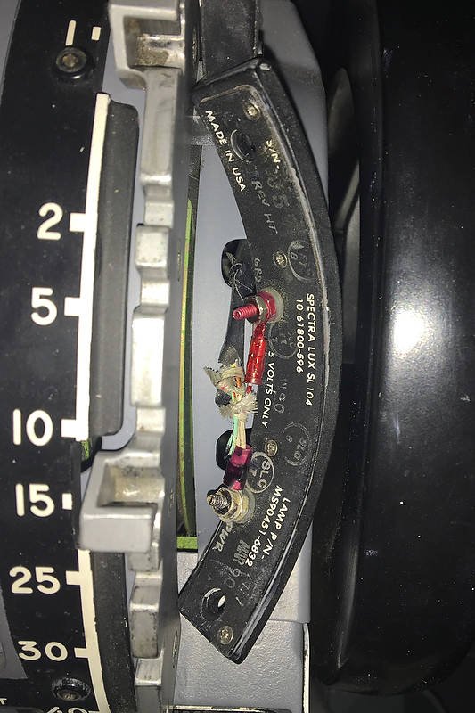
Plastic cover removed and internal bulb holder raised to ninety degrees to facilitate bulb change.  Note the lug on the side of the plastic cover.  Boeing 737-800 Fire Suppression Panel

The Fire Suppression Panel (often called the fire handles) resides in the forward part of the center pedestal.  The three fire handles control the fire suppression used to counter any fire that may develop in the engines or the auxiliary power unit (APU). 

When a fire occurs, the fire bell will sound, the fire warning annunciator on the Master Caution System will illuminate, and the handle on the fire panel, that pertains to the particular engine or APU will illuminate.

The three red-coloured handles are illuminated by four 28 volt incandescent bulbs.  These bulbs are very bright and if the bulbs are not extinguished soon after being illuminated the heat they generate can be substantial.  Although the bulbs have an exceptionally long life cycle, regular testing of the fire handles (every flight) and heat can shorten their lifespan, facilitating a bulb replacement.

Clear covers removed showing four 28 Volt bulbs

Replacing Bulbs

To replace one or all of the bulbs the plastic red-coloured cover must be removed from the handle housing.  This is done by carefully depressing the two 1 cm long lugs on each side of the plastic cover and pulling the cover off the housing.  Often the covers can be brittle, especially if the panel is quite old and well used (heat from the bulbs and UV light can cause the plastic cover to become brittle) therefore, care should be taken when depressing the lugs.

When the cover has been removed, the internal bulb holder (which holds four bulbs) can be lifted out to ninety degrees; the bulbs can now be assessed  Be aware that the bulb holder is not easily removable and is designed to swing out only to a ninety degree angle.

Bulb replacement can be by any voltage bulb, however, 28 volt bulbs are the norm.  Using a lower voltage bulb will lower the illumination (and potential heat) and may make it easier to wire in a simulator environment because a dedicated 28 volt power supply is not required.  

Amperage Draw

The amperage draw from 28 volt bulbs, for example during a lights test, is quite high (three handles, four bulbs in each handle is twelve bulbs), especially when combined with other bulbs being illuminated during the test.  This is why a dedicated 28 volt power supply is recommended for the fire handles.

Important Point:

  • The two lugs on the plastic cover can be easily broken, especially if the plastic is slightly brittle.

Final Call

The fire panel used in the 737 Next Generation has changed little from its predecessors; why redesign something that works flawlessly.  Bulb replacement is straightforward as long as care is taken when removing the plastic fire handle cover.  Although 28 volt bulbs are the norm, replacement can be made by lower voltage bulbs if amperage draw or heat is considered a problem.

B737-600 NG Fire Suppression Panel (Fire Handles) - Evolutionary Conversion Design

737-600 Next Generation Fire Suppression Panel installed to center pedestal.  The lights test illuminates the annunciators
737-600 NG Fire Suppression Panel light plate showing installed Phidget and Phidgets relay card

Originally used in a United Airlines 737-600 Next Generation aircraft and purchased from a wrecking yard, the Fire Suppression Panel has been converted to use with ProSim737 avionic suite. The panel has full functionality replicating the logic in the real aircraft.

This is the third fire panel I have owned.  The first was from a Boeing 737-300  which was converted in a rudimentary way to operate with very limited functionality - it was backliut and the fire handles lit up when they were pulled. The second unit was from a 737-600; the conversion was an intermediate design with the relays and interface card located outside the unit within the now defunct Interface Master Module (IMM).  Both these panels were sold and replaced with the current 600 Next Generation panel. This panel is standalone, which means that the Phidget and relay card are mounted within the panel, and the connection is via the Canon plugs and one USB cable.

I am not going to document the functions and conditions of use for the fire panel as this has been documented very well in other literature.  For an excellent review, read the Fire Protection Systems Summary published by Smart Cockpit.

Nomenclature

Before going further, it should be noted that the Fire Suppression Panel is known by a number of names:  fire protection panel, fire control panel and fire handles are some of the more common names used to describe the unit.

Panel with outer casing removed showing installation of Phidget and and relays.  Ferrules are used for easier connection of wires to the Phidget card.  Green tape has been applied to the red lenses to protect them whilst work is in progress

Plug and Fly Conversion

What makes this panel different from the previously converted 737-600 panel is the method of conversion.  

Rear of panel showing integration of OEM Canon plugs to supply power to the unit (5 and 28 volts).  The USB cable (not shown) connects above the middle Canon plu

Rather than rewire the internals of the unit and connect to interface cards mounted outside of the unit, it was decided to remove the electronic boards from the panel and install the appropriate interface card and relays inside the unit.  To provide 5 and 28 volt power to illuminate the annunciators and backlighting, the unit uses the original Canon plugs to connect to the power supplies (via the correct pin-outs).  Connection of the unit to the computer is by a single USB cable.  The end product is, excusing the pun - plug and fly.

Miniaturization has advantages and the release of a smaller Phidget 0/16/16 interface card allowed this card to be installed inside the unit alongside three standard relay cards.  The relays are needed to activate the on/off function that enables the fire handles to be pulled and turned.

The benefit of having the interface card and relays installed inside the panel rather than outside cannot be underestimated.  As any serious cockpit builder will attend, a full simulator carries with it the liability of many wires running behind panels and walls to power the simulator and provide functionality. Minimising the number of wires can only make the simulator building process easier and more neater, and converting the fire handles in this manner has followed through with this philosophy.

Complete Functionality including Push To Test

The functionality of the unit is only as good as the flight avionics suite it is configured to operate with, and complete functionality has been enabled using the ProSim737 avionics suite. 

One of the positives when using an OEM Fire Suppression Panel is the ability to use the push to test function for each annunciator.  Depressing any of the annunciators will test the functionality and cause the 28 volt bulb to illuminate.  This is in addition to using the lights test toggle located on the Main Instrument Panel (MIP) which illuminates all annunciators simultaneously.

At the end of this post is a short video demonstrating several functions of the fire panel.

The conversion of this panel was not done by myself.  Rather, it was converted by a gentleman who is debating converting OEM  fire panels and selling these units commercially; as such, I will not document how the conversion was accomplished as this would provide an unfair disadvantage to the person concerned.

Differences - OEM verses Reproduction

There are several reproduction fire suppression panels currently available, and those manufactured by Flight Deck Solutions and CP Flight (Fly Engravity) are very good; however, pale in comparison to an OEM panel.  Certainly, purchasing a panel that works out of the box has its benefits; however the purchase cost of a reproduction panel is only marginally less that using a converted OEM panel.

By far the most important difference between an OEM panel and a reproduction unit is build quality.  An OEM panel is exceptionally robust, the annunciators illuminate to the correct light intensity with the correct colour balance, and the tension when pulling and turning the handles is correct with longevity assured.  I have read of a number of users of reproduction units that have broken the handles from overzealous use; this is almost impossible to do when using a real panel.  Furthermore, there are differences between reproduction annunciators and OEM annunciators, the most obvious difference being the individual push to test functionality of the OEM units.

737-300 Fire Suppression Panel. Note the different location of korrys

Classic verses Next Generation Panels

Fire Suppression Panels are not difficult to find; a search of e-bay usually reveals a few units for sale.  However, many of the units for sale are the older panels used in the 737 classic aircraft. 

Although the functionality between the older and newer units is almost identical, the similarity ends there.  The Next Generation panels have a different light plate and include additional annunciators configured in a different layout to the older classic units.

737-300 Fire Suppression Panel. this panel is slightly different to the above panel as it has extra korrys for moreadvanced fire logic

One of the reasons that Next Generation panels are relatively uncommon is that, unless unserviceable, the panels when removed from an aircraft are sold on and installed into another aircraft.

Video

The video demonstrates the following:

  • Backlighting off to on (barely seen due to daylight video-shooting conditions)

  • Push To Test from the MIP (lights test)

  • Push To Test for individual annunciators

  • Fault and overhead fire test

  • Switch tests; and,

  • A basic scenario with an engine 1 fire.

NOTE:  The video demonstrates one of two possible methods of deactivating the fire bell.  The usual method is for the flight crew to disable the bell warning by depressing the Fire Warning Cut-out annunciator located beside the six packs (part of the Master Caution System) on the Main Instrument Panel (MIP).  An alternative method is to depress the bell cut-out bar located on the Fire Suppression Panel. 


737-600 Fire Suppression Panel