Differences in Colour, Manufacturer, and Layout in the Center Pedestal

There are several panels that make up the center pedestal, main instrument panel, and overhead in the Boeing 737 aircraft. Most of the panels are required by international law, and a carrier cannot fly if certain panels do not function correctly.

Although the aviation regulations require aircraft to have certain panels, there are panels that are airline specific. These panels are chosen when the aircraft is ordered from Boeing, or they may be installed at a later on. Similar to automobiles, there are a number of manufacturers of aviation panels and each panel, although having identical functionality may differ slightly.

All high-end simulators replicate the panels required by the authorities, and enthusiasts often fixate on a number of supposed issues. Namely:

(i)         The colour of the panel and lightplate;

(ii)        The position of the panel in the center pedestal;

(iii)       The backlighting of the lightplate (bulbs verses LEDs);

(iv)       The manufacturer of the panel, and;

(v)        The aesthetic condition of the lightplate.

Although seemingly important to a cockpit builder, to the casual observer, or indeed to many pilots, these attributes are of little consequence.  Nevertheless, it's understandable to a newcomer that all panels in the 737 Next Generation are identical between all aircraft.

Whilst it's true that all airlines must meet aviation standards for the type of operation they fly, the panel manufacturer and where in the pedestal the panel is located is at the discretion of the airline.  Furthermore, it's not uncommon to observe older style panels mixed with modern panels and to see lightplates that are illuminated by bulbs and LEDs side by side.

Note that some of this information probably pertains more to older Next Generation 737s than to the latest Next Generation released from Boeing.  I use the word 'panel' to denote an avionics module.

Air Alaska 737-700 pedestal.  Note higher than standard position of ACP panels and relocated position of the door lock panel.  Also high mounted position of rudder trim panel

Colour of Lightplates

The official colour shade used by Boeing is Federal Standard 5956 36440 (light gull grey).  However, OEM part manufacturers may use slightly different colour hues.  For example, IPECO use British Standard 381C-632 (dark admiralty grey) and Gables use RAL 7011.  This said, often an airline will 'touch up' a lightplate that is damaged or faded - this introduces a further colour variant. 

For example, a lightplate I acquired from a 737-500 airframe revealed three differing shades of grey beneath the final top coat of paint.  This is not to mention that, depending on the manufacturer of the lightplate, the final coat of paint may be matt, semi-matt or gloss.

From the perspective of an engineer, the colour (and to a certain extent aesthetic condition) is unimportant when replacing a defective part with another.  Time spent in the hanger equates to a loss in revenue by the airline.  Therefore turn-around times are as brief as possible and keeping an aircraft on the ground while procuring the correct shade of Boeing grey does not enter the equation.

Position of Panels in the Center Pedestal

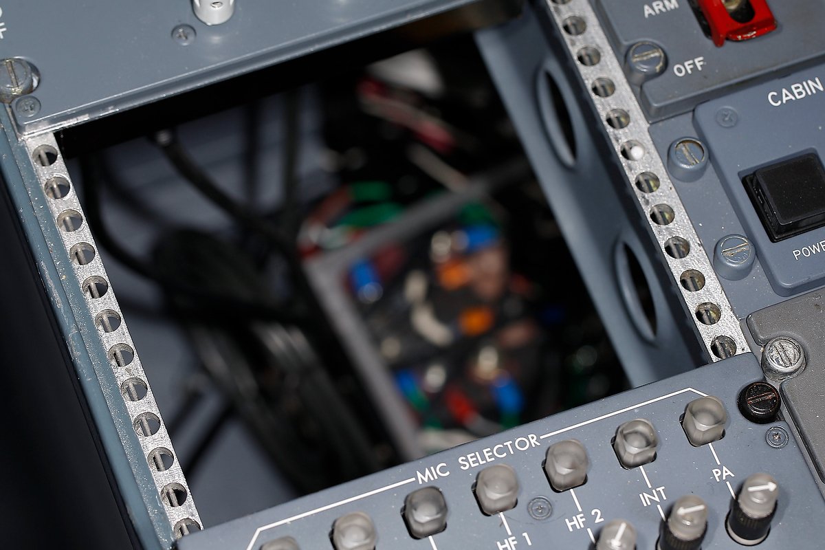
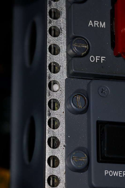
Boeing recommends a more or less standard position for the essential panels in the center pedestal (NAV, COM, ADF, ASP, rudder trim, door lock and panel flood), however, the location of the panels is often altered by the receiving airline, and is to a certain extent is determined by what other panels are installed to the pedestal.  Areas (holes) in the pedestal not used by a panel are covered over with a grey-coloured metal blank.

LEFT:  This photograph of the center pedestal of a Boeing 737-500 was taken in 2016.  The aircraft is a freighter converted from a passenger aircraft.  Apart from the older style ACP panels, note the disparate displays between the NAV and COM radios.  Also note the position of the ADF radios and some of the other panels; they do not conform to what is usually thought of as a standard set-out.  Finally, note the scratches on the pedestal and on some of the panels and lightplates - they hardly look new.

Panels are manufactured by several companies, and often there appearance will differ slightly between manufacturer, although the panel's functionality will be identical.  The airline more often than not chooses which panel is used, and often the decision is biased by the cost of the panel.  Therefore, it's not uncommon to observe several airframes of a similar age with differing panels positioned in different areas of the center pedestal.
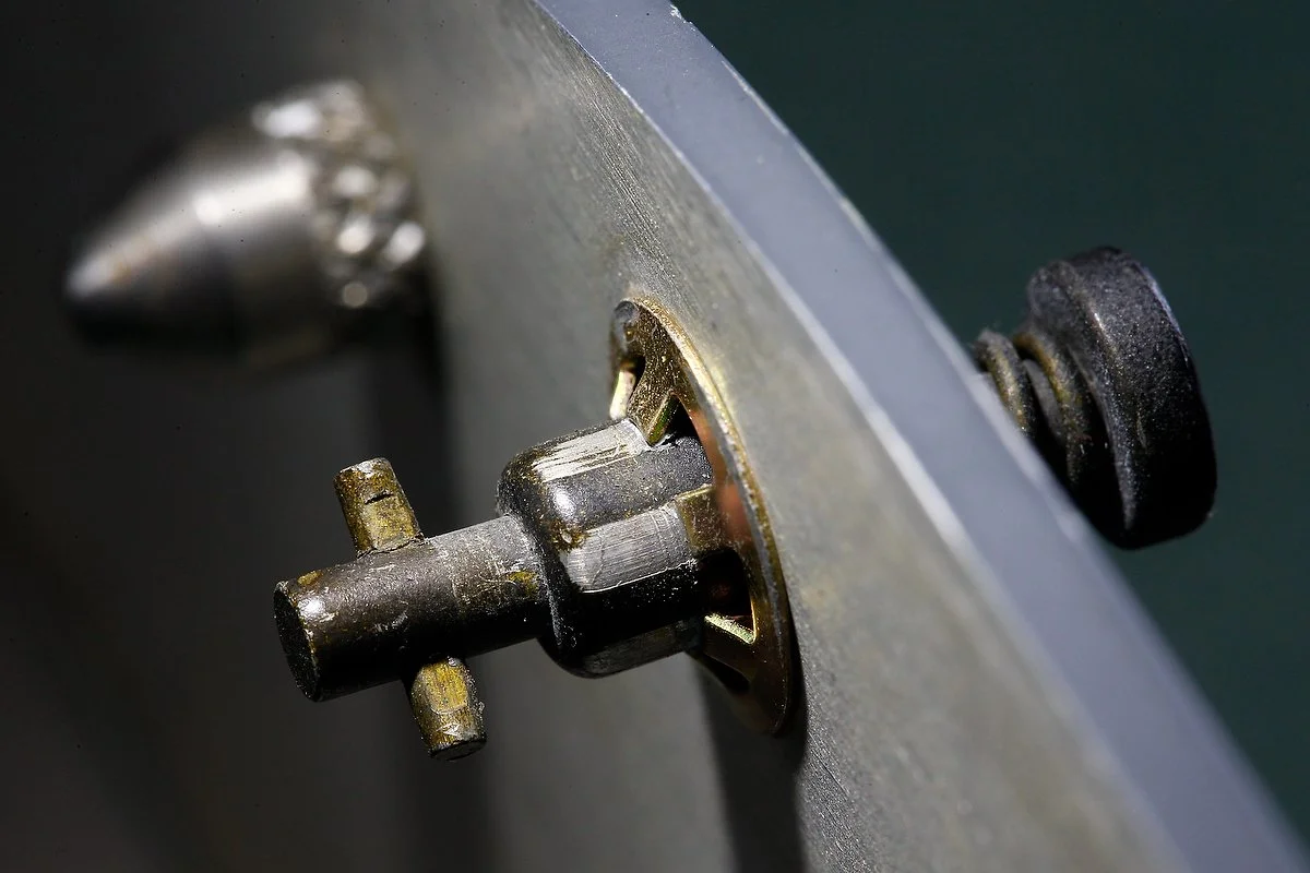
Panel Condition

Enthusiasts pride themselves in having a simulator that looks brand new.  However, in the real world a Level D simulator or flight deck rarely looks new after entering service.  Panels can be soiled and paint is chipped and scratched, and depending on age, some lightplates are faded to due to the high UV environment that is present in a flight deck.

So where am I going with this?  Enthusiasts strive to match their panels with those observed in a real airliner, however, more often than not this information comes from photographs distributed by Boeing Corporation, which nearly always depict panels in a standard position, especially in relation to the center pedestal. 

The variables noted by enthusiasts should not cause consternation, as real aircraft show similar variation.  Remember that in the real aircraft, colour, manufacturer, and to a certain extent aesthetic condition is not important - functionality is.

Throttle Quadrant Rebuild - New Wiring Design and Rewiring of Center Pedestal

oem 737-500 center pedestal. the panels change as oem components are purchased and converted

Put bluntly, the wiring in the center pedestal was not to a satisfactory standard.  Several panels were daisy chained together, the wires were not colour coded, and the pedestal looked like a rat’s nest of wires.  Likewise, the wiring of the Master Caution System (MCS) required upgrading as several of the original wires showed signs of fraying.  

A word of thanks goes to a friend (you know who you are...) who helped wade through the labyrinth of wires!

This post shares several links to other pages in the website.

Wiring Redesign (pedestal and panels)

The set-out of the inside of the center pedestal was redesigned from the ground up, and several of the pedestal panels re-wired to ensure conformity to the new design standard, which was neater and more logical than its predecessor.  Additionally, the MCS was rewired using colour-coded wire and the wires labeled accordingly.

New Design (panels must be stand-alone)

The new design called for each panel (module) that was installed into the pedestal to be stand-alone.  Stand-alone means that if removal of a panel was necessary, it would be a simple process of unscrewing the DZUS fasteners, lifting the panel out and disconnecting a D-Sub plug and/or 5 volt backlighting wire.   Doing this with panels that were daisy chained together was impossible.

The following panels have been re-wired:

(i)      EVAC panel;

(ii)     Phone panel;

(iii)   ACP units (2);

(iv)    On/off lighting/flood panel; and,

v)      Radar panel.

737-800 EVAC panel, although not a panel that resides in the pedestal, it demonstrates the 'stand-alone' panel philosophy.  One D-Sub plug with labelled and colour-coded wire.  The mate of the D-sub resides inside the pedestal with the wires connected to the appropriate busbar

All the panels have been retrofitted with colour-coded and labeled D-Sub connections.  Removing a panel is a simple as unfastening a DZUS connector, disconnecting a D-Sub connector, and unscrewing the 5 volt backlighting wire from the 5 volt terminal block (if ued).  If a USB cable is needed for the panel, then this must also be disconnected.

A word concerning the ACP units, which were converted some time ago with an interface card located on a separate board outside of the unit.  As part of the rebuild, the two ACP units were completely re-wired to include the interface card within the unit.  Similar to the fire suppression panel, the ACP units are now stand-alone, and only have one USB cable which is used to connect to the computer.  The First Officer side ACP is daisy chained to the Captain-side unit.

Center Pedestal Flat Board

A flat board 1 cm in thickness and constructed from wood was cut to the same dimensions of the pedestal base.  The board was then attached to the inside bottom of the pedestal by screws.  The wood floor has been installed only to the rear two thirds of the pedestal, leaving the forward third open to allow easy access to the platform floor and area beneath the floor structure..

Attached to the flat board are the following items:

(i)       FDS 5 Volt IBL-DIST panel power card (backlighting for FDS panels);

(ii)      28 Volt busbar;

(iii)     5 Volt busbar (backlighting);

(iv)     12 Volt relay (controls backlighting on/off tp panel knob);

(v)      Terminal block (lights test only);

(vi)     Light Test busbar;

(vii)    OEM aircraft relay; and a,

(viii)    Powered USB hub (NAV, M-COM, ACP & Fire Suppression Panel connection).

The 5, 12 and 28 volt busbars (mounted on the flat board) receive power continuously from the power supplies, mounted in the Power Supply Rack (PSR) via the System Interface Module (SIM). Each panel then connects directly to the respective busbar depending upon its voltage requirement.  

In general, 5 volts is used for panel backlighting while 12 and 28 volts is used to power the fire suppression panel, EVAC, throttle unit, phone panel and other OEM components

The flat board has a fair amount of real-estate available; as such, expanding the system is not an issue if additional items need to be mounted to the board.

Lights Test busbar.  Similar in design to the 5 volt busbar, its use centralizes all wires and reduces  the number of connections to a power supply.  Despite the pedestal rewire, there is still a lot of loose wire that cannot be 'cleaned up'.  The grey coloured object is the flat board

Lighting Panel Knob (backlighting on/off)

All the panels in the center pedestal require 5 volt power to illuminate the backlighting.  The general purpose knob located on the pedestal OEM lights panel is used to turn the backlighting on and off.  

Instead of connecting each panel’s wire to the on/off lights panel knob – a process that would consume additional wire and look untidy, each wire has been connected to a 10 terminal 5 volt busbar.  The busbar in turn is connected to a 12 volt relay which is connected directly with the on/off knob.

When panel lights knob is turned from off to on, the relay closes the circuit and the busbar is energised; any panel connected to the busbar will automatically receive power.

The busbar and relay are mounted to the flat board.

This system has the advantage that it minimizes the number of wires that are connected to the lights panel knob.  It also enables one single high capacity wire to connect from the relay to the knob rather than several smaller gauge wires.  This minimises the heat produced from using several thinner wires.  It is also easier to solder one wire to the rear of the panel knob than it is to solder several wires.

Lights Test and DIM Functionality

The center pedestal also accommodates the necessary components (Lights Test busbar) to be able to engage the Lights Test and DIM functionality.  These functions are triggered by the Lights Test Toggle located on the Main Instrument Panel (MIP).  

All wires have been corrected colour coded to various outputs and wire ends use ferrules to connect to the card

Interface Cards

In the previous throttle quadrant, a number of interface cards were mounted within the center pedestal. 

To ensure conformity, all the interface cards have been removed from the pedestal and are now mounted within one of the interface modules located forward of the simulator. 

Furthermore, all the wiring is colour-coded and the wire ends that connect into the I/O cards use ferrules.

The First Officer-side MCS completely rewired.  The MCS has quite a bit of wiring, and making the wire neat and tidy, in addition to being relatively accessible, was a challenge

The use of ferrules improves the longevity of the wiring, makes wire removal easier, and looks neater.

Wiring and Lumens

Needless to say, the alterations have necessitated rewiring on a major scale.  Approximately 80% of the internal wiring has had to be replaced and/or re-routed to a position that is more conducive to the new design.

The majority of the wiring required by the throttle unit now resides in a lumen which navigates from the various interface modules (located forword of the simulator) to the Throttle Communication Module (TCM).  

From the TCM the lumen routes through the throttle firewall, along the Captain-side of the throttle unit before making its way to the flat board in the center pedestal.  

The exception to the above is the cabling required for a powered USB hub located within the center pedestal, the wires required for the Lights Test (from the Lights Test Toggle located in the MIP), and the various power wires navigating to the pedestal from the Power Supply Rack.  These wires have been bundled into a separate lumen, which resides beneath the floor structure.

Identifying the voltage of wires is an important aspect of any simulation build

Wire Management

Building a simulator using OEM parts, requires an inordinate amount of multi-voltage wiring of various gauges, and it can be challenge to maintain the wire in a neat and tidy manner. 

Running the wire through conduits and lumens does help, but in the end, due to the amount of wire, the number of connections, and the very limited space that is available, the wire is going to appear a little messy.  Probably more important, is that the wire conforms to an established design standard – meaning it is colour-coded and labelled accordingly.

A dilemma often facing builders is whether to use electrical tape to secure or bind wires.  Personally, I have a strong dislike for electrical tape - whilst it does have its short-term usages, it becomes sticky very easily, and becomes difficult to remove if left on wires for a considerable time .

My preferred method is to use simple cable ties, snake skin casing, or to protect the wires near terminals of OEM parts. to use electrical shrink tubing (which can be purchased in different colours for easy identification of wires and terminals).

Final Product

The design and rewiring of many parts in the simulator has been time consuming.  But, the result has been:

(i)     That all the wires are now colour-coded and labelled for easy identification;

(ii)     The wiring follows a defined system in which common-themed items have been centralised.  

(iii)    Panels that were daisy chained have been rewired with separate D-Sub plugs so they are now stand-alone;

(iv)    The  frayed wires from the MCS have been replaced with new wires; and,

(v)    The wires in general are neater and more manageable (the rat's nest is cleaner...).

B737-600 NG Fire Suppression Panel (Fire Handles) - Evolutionary Conversion Design

737-600 Next Generation Fire Suppression Panel installed to center pedestal.  The lights test illuminates the annunciators

737-600 NG Fire Suppression Panel light plate showing installed Phidget and Phidgets relay card

Originally used in a United Airlines 737-600 Next Generation aircraft and purchased from a wrecking yard, the Fire Suppression Panel has been converted to use with ProSim737 avionic suite. The panel has full functionality replicating the logic in the real aircraft.

This is the third fire panel I have owned.  The first was from a Boeing 737-300  which was converted in a rudimentary way to operate with very limited functionality - it was backliut and the fire handles lit up when they were pulled. The second unit was from a 737-600; the conversion was an intermediate design with the relays and interface card located outside the unit within the now defunct Interface Master Module (IMM).  Both these panels were sold and replaced with the current 600 Next Generation panel. This panel is standalone, which means that the Phidget and relay card are mounted within the panel, and the connection is via the Canon plugs and one USB cable.

I am not going to document the functions and conditions of use for the fire panel as this has been documented very well in other literature.  For an excellent review, read the Fire Protection Systems Summary published by Smart Cockpit.

Nomenclature

Before going further, it should be noted that the Fire Suppression Panel is known by a number of names:  fire protection panel, fire control panel and fire handles are some of the more common names used to describe the unit.

Panel with outer casing removed showing installation of Phidget and and relays.  Ferrules are used for easier connection of wires to the Phidget card.  Green tape has been applied to the red lenses to protect them whilst work is in progress

Plug and Fly Conversion

What makes this panel different from the previously converted 737-600 panel is the method of conversion.  

Rear of panel showing integration of OEM Canon plugs to supply power to the unit (5 and 28 volts).  The USB cable (not shown) connects above the middle Canon plu

Rather than rewire the internals of the unit and connect to interface cards mounted outside of the unit, it was decided to remove the electronic boards from the panel and install the appropriate interface card and relays inside the unit.  To provide 5 and 28 volt power to illuminate the annunciators and backlighting, the unit uses the original Canon plugs to connect to the power supplies (via the correct pin-outs).  Connection of the unit to the computer is by a single USB cable.  The end product is, excusing the pun - plug and fly.

Miniaturization has advantages and the release of a smaller Phidget 0/16/16 interface card allowed this card to be installed inside the unit alongside three standard relay cards.  The relays are needed to activate the on/off function that enables the fire handles to be pulled and turned.

The benefit of having the interface card and relays installed inside the panel rather than outside cannot be underestimated.  As any serious cockpit builder will attend, a full simulator carries with it the liability of many wires running behind panels and walls to power the simulator and provide functionality. Minimising the number of wires can only make the simulator building process easier and more neater, and converting the fire handles in this manner has followed through with this philosophy.

Complete Functionality including Push To Test

The functionality of the unit is only as good as the flight avionics suite it is configured to operate with, and complete functionality has been enabled using the ProSim737 avionics suite. 

One of the positives when using an OEM Fire Suppression Panel is the ability to use the push to test function for each annunciator.  Depressing any of the annunciators will test the functionality and cause the 28 volt bulb to illuminate.  This is in addition to using the lights test toggle located on the Main Instrument Panel (MIP) which illuminates all annunciators simultaneously.

At the end of this post is a short video demonstrating several functions of the fire panel.

The conversion of this panel was not done by myself.  Rather, it was converted by a gentleman who is debating converting OEM  fire panels and selling these units commercially; as such, I will not document how the conversion was accomplished as this would provide an unfair disadvantage to the person concerned.

Differences - OEM verses Reproduction

There are several reproduction fire suppression panels currently available, and those manufactured by Flight Deck Solutions and CP Flight (Fly Engravity) are very good; however, pale in comparison to an OEM panel.  Certainly, purchasing a panel that works out of the box has its benefits; however the purchase cost of a reproduction panel is only marginally less that using a converted OEM panel.

By far the most important difference between an OEM panel and a reproduction unit is build quality.  An OEM panel is exceptionally robust, the annunciators illuminate to the correct light intensity with the correct colour balance, and the tension when pulling and turning the handles is correct with longevity assured.  I have read of a number of users of reproduction units that have broken the handles from overzealous use; this is almost impossible to do when using a real panel.  Furthermore, there are differences between reproduction annunciators and OEM annunciators, the most obvious difference being the individual push to test functionality of the OEM units.

737-300 Fire Suppression Panel. Note the different location of korrys

Classic verses Next Generation Panels

Fire Suppression Panels are not difficult to find; a search of e-bay usually reveals a few units for sale.  However, many of the units for sale are the older panels used in the 737 classic aircraft. 

Although the functionality between the older and newer units is almost identical, the similarity ends there.  The Next Generation panels have a different light plate and include additional annunciators configured in a different layout to the older classic units.

737-300 Fire Suppression Panel. this panel is slightly different to the above panel as it has extra korrys for moreadvanced fire logic

One of the reasons that Next Generation panels are relatively uncommon is that, unless unserviceable, the panels when removed from an aircraft are sold on and installed into another aircraft.

Video

The video demonstrates the following:

  • Backlighting off to on (barely seen due to daylight video-shooting conditions)

  • Push To Test from the MIP (lights test)

  • Push To Test for individual annunciators

  • Fault and overhead fire test

  • Switch tests; and,

  • A basic scenario with an engine 1 fire.

NOTE:  The video demonstrates one of two possible methods of deactivating the fire bell.  The usual method is for the flight crew to disable the bell warning by depressing the Fire Warning Cut-out annunciator located beside the six packs (part of the Master Caution System) on the Main Instrument Panel (MIP).  An alternative method is to depress the bell cut-out bar located on the Fire Suppression Panel. 


737-600 Fire Suppression Panel


B737 Center Pedestal Completed and Installed - Flight Testing Begins

oem 737-500 center pedestal and custom panels.  The center pedestal from the 500 series is very similar to that of the next generation

After spending the best part of two weeks wiring the various panels into the center pedestal I am now pleased with the result. 

The center pedestal is from a Boeing 737-500 and is made from fibreglass.  The earlier series two-bay pedestals were made from aluminium.  The three bay pedestal allows much more room inside the pedestal to mount interface cards and house the wiring for the various panels (modules). 

However, as with every positive there often is a drawback.  In this case there are two drawbacks.  The first is a few spare holes must be covered with OEM blanking plates, and the second is the three bay pedestal is considerably wider than a two bay pedestal.  Whilst climbing into the flight deck is easy at the moment, once a shell is fitted, J-Rails will need to be fitted to the seats to allow easy access. 

Space

Taking advantage of the extra internal space of a three bay, I have constructed a small shelf that fits inside the lower section.  The shelf is nothing fancy - a piece of wood that fits securely between the two sides of the pedestal.  Attached to this shelf are bus bars, a Leo Bodnar interface card and a FDS interface card.  A Belkin powered hub also sits on the shelf.  The power supply for the hub resides beneath the platform to the rear ( for easy access).

The bus bars provide power for the various OEM panels and backlighting, while the Leo Bodnar card provides the interface functionality for the two ACP units.  The FDS card is required for operation of the three FDS navigation and communication radios I am currently using.

My aim was to minimise cabling from the pedestal forward to the throttle unit.  The reason for this is the throttle is motorized and moving parts and USB cables do not work well together.  I have two cables that go forward of the pedestal to the computer; one USB cable from the powered Belkin hub and the other the cable required to connect the CP Flight panels.  Both cables have been carefully routed along the inner side of the throttle quadrant so as to not snag on moving internal parts.

Pedestal Colour

The original pedestal was painted Boeing grey which is the correct colour for a B737-500.  The unit was repainted Boeing white to bring it into line with the colour of the B737-800 NG pedestal.

oem 737-500 center pedestal illuminated by 5 volt incandescent bulbs

Backlighting

The backlighting for the throttle quadrant and center pedestal is turned on or off by the panel knob located on the center pedestal.  Power is from a dedicated S-150 5 Volt power supply rated to 30 amps. 

On the Seventh day, GOD created backlighting and the backlighting was said to be good”.

The light plates are mostly aircraft bulbs; however, a few of the panels, such as the phone and EVAC panel, are LEDS and operate on 28 Volts rather than the standard 5 Volts.

Size Does Matter...

It's important when you install the wiring for backlighting that you use the correct gauge (thickness) wire.  Failure to do this will result in a voltage drop (leakage), the wire becoming warm to touch, and the bulbs not glowing at their full intensity.  Further, if you use a very long wire from the power supply you will also notice voltage drop; a larger than normal wire (thickness) will solve this problem.  There is no need to go overboard and for average distances (+-5 meters) standard automotive or a tad thicker wiring is more than suitable to cater to the amp draw from incandescent bulbs.

To determine the amperage draw, you will need to determine how many amps the bulbs are using.  This can be problematic if you're unsure of exactly how many light plates you have.  There are several online calculators that can be googled to help you figure out the amperage draw.  Google "calculation to determine wire thickness for amps".

At the moment, I am not using a dimmer to control the backlighting, although a dimmer maybe installed at a later date.

Minor Problem - Earth Issue

A small problem which took considerable time to solve was an earth issue.  The problem manifested by arcing occurring and the backlighting dimming.  I attempted to solve the problem by adding an earth wire from the pedestal to the aluminium flooring; however, the issue persisted.  The issue eventually was tracked down to an OEM radar panel which was "earthing" out on the aluminum DZUS rails via the DZUS fasteners.  To solve the problem, I sealed the two metal surfaces with tape.

Panels

The panels I am currently using are a mixture of Flight Deck Solutions (FDS), CP Flight, 500 and Next Generation:

  • NAV 1/2 (FDS)

  • M-COM (FDS)

  • ADF 1/2 (CP Flight) - replaced with FDS

  • Light Panel (OEM)

  • Radar Panel (OEM)

  • EVAC Panel (OEM)

  • Phone Panel (OEM)

  • Rudder Trim Panel (CP Flight) - replacd with OEM

  • ATC Transducer Radio (OEM)

  • ACP Panel x 2 (OEM)

  • Fire Suppression Panel (OEM)

In time a ACARS printer will be added and some of the non NG style panels (namely the ACP panels) will be replaced with OEM NG style ACP panels.  The OEM panels installed are fully operational and have been converted to be used with Flight Simulator and ProSim737.  I will discuss the conversion of the panels, in particular the Fire Suppression Panel, in separate journal posts.

The more observant readers will note that I am missing a few of the "obvious" panels, namely the cargo fire door panel and stab trim panel.  Whilst reproduction units are readily available, I'm loathe to purchase them preferring to wait; eventually I'll source OEM panels.  Rome was not built in a day.

Panel Types

If you inspect any number of photographs, it will become apparent that not all aircraft have exactly the same type or number of panels installed to the pedestal.  Obviously, there are the minimum requirements as established by the relevant safety board; however, after this has been satisfied it's at the discretion of the airline to what they order and install (and are willing to pay for...).  It's not uncommon to find pedestals with new and old style panels, incandescent and LED backlighting, colour differences and panels located in different positions.

oem 737-500 center pedestal telephone. although not next generation it completes the pedestal

Telephone Assembly

Purists will note that the telephone is not an NG style telephone and microphone.  I have keep the original B737-500 series telephone and microphone as the pedestal looks a little bare without them attached. 

If at some stage I find a NG communications assembly I'll switch them, but for the time being it will stay as it is.

Flight Testing - Replication

The throttle quadrant and center pedestal are more or less finished.  The next few weeks will be spent testing the unit, it's functionality, and how well it meshes with ProSim737 in various scenarios.  This process always takes an inordinate amount of time as there are many scenarios to examine, test and then replicate. 

Replication is very important as, oddly, sometimes a function will work most times; however, will not work in certain circumstances.  It's important to find these gremlins and fix them before moving onto the next level. 

KIS - Keep It Simple

Although everything is relatively simple in design (OEM part connects to interface card then to ProSim737 software), once you begin to layer functions that are dependent on other functions working correctly, complexity can develop.   It's important to note that the simulator is using over a dozen interface and relay cards, most mounted within the Interface Master Module (IMM) and wired to an assortment of OEM parts configured to operate with ProSim737's avionics suite. 

B737-800 Cabin Phone System Panel - Center Pedestal

oem 737-800 cabin phone panel: Panel has three push buttons with backlighting and legends, and one toggle button

I recently acquired an avionics panel that is a little different to the norm.  The panel was acquired from a company that was responsible for altering the on-board communication system for 50 Boeing 737-800 jetliners; the aircraft were being refitted with global communication equipment.  The upside for me was that the panels were being decommissioned and were not required by the supplier.

Late model 737 Next Generation panels are uncommon to find; therefore, it is interesting to observe the differences between the older style classic panels regularly seen on e-bay, and a newer style panel. 

The first thing that comes to mind, other than condition, is the lack of a rear box assembly on this panel.  Instead of an aluminum box, the wiring is protected by a stainless bracket assembly.  The wiring harness is also more refined and neater looking, while the backlighting, rather than using 5 Volt bulbs uses LED technology.

oem 737-800 cabin phone panel. note the crispness of the legend

LED Technology

Most people are familiar with the 5 volt incandescent bulbs used to illuminate the light panels in Boeing aircraft - the bulbs produce a soft yellow-orange hue.  The colour temperature is in stark contrast to the white hue produced by LED technology. 

I believe that airframes post 2006 utilise LED technology.  Notwithstanding this, until older airframes are phased out, panel lighting will be a mixture of incandescent and LED lighting, or a combination thereof. 

Matching Colour Hue

Attempting to match the backlighting colour hue, especially in the center pedestal and overhead panels has always been a challenge for flight deck builders, especially when using an assortment of older style OEM panels and panels made by differing companies (FDS, CP Flight, Open Cockpits, SimWorld, etc).  

Wiring is very neat and the panel does not utilise the more commonly found aluminum box structure

What many virtual pilots forget, is that the only purpose for an airlines’ existence is to generate income and a profit for the company. Pilots on the other hand are more concerned with flying the aircraft. 

There is very little thought as to whether a panel's backlighting is the same colour hue throughout all the panels.  If and when a panel needs to be replaced, a technician’s only concern is getting a workable and certified instrument fitted into the aircraft as quickly as possible. 

it is not unrealistic to have a few LED panels scattered amongst older bulb illuminated panels

Cabin Phone System Panel - What Works

Although there is no obvious use for this panel in the simulator, it is a good-looking panel that improves the overall aesthetics - it fills a 'gap' in the three-bay center pedestal.  The buttons do function and when depressed change colour and provide different cautionss.  Lifting the red cover and pushing the toggle to test causes the third button to illuminate 'smoke' in orange.

Although the panel has not been connected to an interface card, it is an easy process to connect a PoKeys or Leo Bodnar interface card to the Canon plug. ProSim737, nor Sim Avionics include functionality with this panel.

B737 Blanking Plates - Cover That Unsightly Gap

OEM blanking plates complete with DZUS fasteners recently removed from a scrapped 737 - the dirt and dust is still on them!  Note three differing sizes - 1" 2" and 4"

No matter what style of simulator you are using or have constructed, you will most likely have a center pedestal installed.  The pedestal will be either a two-bay or three-bay type and be a genuine aviation part incorporating DZUS fastener rails, or a reproduction unit manufactured from wood, metal or plastic.

The two-bay pedestals, once allotted the standard Boeing avionics suite, usually have no  space remaining for additional avionics; however, the three-bay pedestals have substantially more 'real estate' and often gaps are remaining that are not filled with avionics.  Most enthusiasts either leave this space open which looks very unsightly, or manufacture their own plate to cover the gap.

OEM Blanking Plates

Why not use the real part….  

Boeing produces several blanking plates in varying sizes to be used to cover any 'gaps' not used in the center pedestal, forward and aft overhead panel, or Main Instrument Panel (MIP).  These plates are machine-grade light weight steel (or aluminum), are painted Boeing grey, and incorporate the required number of DZUS fasteners for attachment to DZUS rails.  The plates come in a variety of sizes with 1 inch, 2 inch, and 4 inch being the norm.

These plates are inexpensive and usually retail between $5.00 - $20.00 USD, and not only fulfill the task of covering an unsightly gap, but are easy to install, come pre-cut, are painted the right colour, and usually have DZUS fasteners attached to them. 

If not using real DZUS rails and your pedestal in made from wood or plastic, then it’s relatively easy to remove the fasteners and replace them with reproduction screw-type DZUS available from GLB Products.

Most aircraft wrecking yards carry these plates, as airlines regularly purchase them.  Failing this E-Bay often has blanking plates for sale. 

Converting Genuine B737 Audio Control Panels (ACPs)

oem 737-400 ACP. this will be a filler until two next generation ACPs are found

I have looked at several commercially made Audio Control Panels that are available for connection to flight simulator – I did not like any of them.  They all seemed to lack a certain degree of authenticity, whether it was the LED backlighting rather than bulbs, poorly designed and moulded switches, or out of alignment cheap-looking plastic buttons.  The only ACP units that interested me where those produced by Flight Deck Solutions, however, the price for two units was greater than purchasing two genuine second-hand ACP units. 

What is an ACP

ACP stands for Audio Control Panel and the B737 has three units; one in the aft overhead and two (captain & first officer) in the center pedestal.   Each panel controls an independent crew station audio system and allows the crew member to select the desired radios, navigation aids, interphones, and PA systems for monitoring and transmission. Receiver switches select the systems to be monitored.  Any combination of systems may be selected. Receiver switches also control the volume for the headset and speaker at the related crew stations. Audio from each ACP is monitored using a headset/headphones or the related pilot’s speaker.

Simply, the ACP is a glorified sound mixer.

Finding second-hand ACP units from a B737-800NG is next to impossible, so the next best thing are units removed classic series 737s.  The units I am using were manufactured by Gables Engineering in 2004 and have been removed from a B737-500.  It is unlikely that ACP units from an earlier series aircraft would be used in the NG, as the NG ACP unit design is different.  But, for a home-made simulator the use of older ACP units fulfils the same roll and is a very good stop-gap until a OEM NG panel can be procured.

When you begin to search for ACP units, you will discover there are a large number of different designs available.  The design can be correlated to the era of the unit.  Earlier units used sliders and turn dials while later models utilised push buttons.   Many of the slider-style units were used in 727s. 

Conversion of ACP Unit to Flight Simulator - Several Methods

It is difficult to document exactly how a conversion is done.  There are many variables to consider and genuine parts and flight simulator set-ups can be different.  By far the most challenging task is determining which wire from the 55 pin plug controls which ACP function.

oem 737-400 ACP unit with outer shell removed.  Most of this will be removed with the exception of the switches.  The wiring can be removed and replaced or unraveled and used directly

Removing Unwanted Wiring

You can either start afresh and after removing the outer aluminium casing, strip most of the wiring from the unit, along with discarding unwanted solenoids, relays and the large circular 55 pin plug at the rear of the unit; or keep the wiring and 55 pin plug and attempt to determine which wire goes where and and connects with what function. 

When finished removing much of the unwanted interior you will be left an almost empty container and some hardware and electrical circuits (buttons and switches).  Most of the switches are triple push switches and you must be careful to not damage the internal mechanism of these switches.

Which Wire Goes Where and Connections

There are two ways to convert the unit:  The first is to use existing wiring and determine which wire goes to what button/switch to reflect whatever functionality; this can be a time-consuming, challenging and frustrating task.  Once the wire to a function has been found, you must identify the wire with a flat tab or other physical marking device.  Each wire is then directed to an interface card.

The second method is a little easier.  Remove all the wires are rewire the unit.  This way there is no double-guessing that you have the correct wire.

If you have opted for the slightly easier second method of removing all the wiring from the unit and starting afresh, you can now recycle the same wire and solder the wires to the appropriate switches.  Recycling in motion :)

Determining Functionality

One method to determine functionality is to use a digital multi meter.  Set the meter to either continuity or resistance, select a wire connected to a switch and place the probe at the open end of the wire.  Identifying the correct wire/switch will cause the meter to either emit an audible beep or display a resistance on the display.  This is the wire that connects this function.

Once the wires have been identified and connected to the correct hardware switches within the ACP unit, they are then connected to an interface card.  I have used a Leo Bodnar BU0836X card which has available a large number of inputs and outputs. 

The Leo Bodnar card provides the interface between the ACP units and flight simulator.

To keep the wiring tidy, bundle the wires into a wiring lumen terminating in a solid plug / connector.  In my case I've used a standard style 18 pin computer connector. 

It is important to use a plug, rather direct the wires directly to the interface card, as you may wish to remove the ACP units at some stage.  A plug allows easy removal and connection.

Leo Bodnar card and two wire rails connected to acyclic board.  The vertically mounted wire rail provides a strong support from which to solder the wires.  The two computer plugs connect to the rear of each ACP unit.  The other small blue coloured card is an FDS power connection card used to daisy chain 5 Volt  power to the FDS modules I am using

Wiring Harness, Rail and Backlighting

A wiring harness was constructed to facilitate easier connection of the wires from the ACP units to the interface card. The harness and Leo Bodnar card is attached to a thick piece of acrylic plastic which in turn was mounted to a piece of wood that fits snugly within the center pedestal.

Wire Rail

Each ACP unit has a dedicated 'wire rail' attached to an acrylic plastic base.  The purpose of this rail is to provide an interface between the ACP units and the Leo Bodnar card.  Whilst this interface is not absolutely necessary, it does allow for identification of the wires (numbering system seen in photograph above).  Furthermore, it also provides a stable and solid base to secure wires between the interface card and each of the ACP units.

It should be noted that the rail also acts as a Y-junction to filter the outputs from two ACP units into one, which connects to the interface card and flight simulator.

The wires from the rail are then soldered to a standard style computer plug which connects to its male  equivalent mounted to the rear of each ACP unit. In essence we have three parts to the system:

  1. A re-wired ACP unit with wires terminating in a plug on the rear of the unit. 

  2. A wire rail which sits between the two ACP units and the interface card (Y-junction).

  3. An interface card that  connect with the wire rail and then to flight simulator via a USB cable.

Soft amber glow of ACP unit back lighting at night.  The light plates of genuine units always use globes rather than LED lights.  Power is 5 Volts DC and the amperage draw is around 1 AMP

Backlighting

The wires which carry power to illuminate the back lighting are wired directly from the light plates located in each ACP unit to a small electrical terminal block mounted to the rear of the unit.  The power wire is then directed to the panel light switch, located on the center pedestal. 

The panel light switch, located on the center pedestal,  controls back-lighting to the throttle quadrant, center pedestal and to the trip indicators on the yokes.  The reason for breaking this power wire with a two-wire terminal block is to allow removal of the ACP unit if necessary.  If you wanted to, you could use a pencil style audio push-in style plug.

A single USB cable from the Leo Bodnar card connects the ACP units to the main FS computer.

Synchronised Units - Limiting FSX Factor

In a real aircraft each ACP unit is separate to each other and can be configured independently, however, flight simulator (FSX) falls short in this area and uses only one ACP unit to mimic button presses across all units. As such, it was pointless to wire each unit separately and independent of each other.  Therefore, both ACP units mimic each other in functionality and output. 

For example, the ADF1 button can be pressed on the captain-side ACP unit to turn ADF1 on.  If you then press the same button on the flight officer side unit, ADF1 will be turned off.  This is another reason why a wire rail, mentioned above, was used; to act as a Y-junction.

NOTE (January 2015): ProSim737 now allows configuration of all buttons on the Captain and First Officer ACP units.  ProSim737 now allows independent selection of an ACP unit (up to three) removing the earlier FSX-imposed limiting factor.  Both units have been re-wired to take this into account.

Converted ACP unit showing replacement wiring and 18 pin computer style plug.  The circular hole in the rear below the plug is where the 55 pin plug was removed

Control - Captain or First Officer

Some enthusiasts wire units so that the Captain side is always the main controlling unit.  In my set-up, the wires from each ACP unit are fixed to the 'wire rail' and then to the Leo Bodnar card.  This allows you to be able to choice either side as the controlling unit.  The downfall being that whatever side is not in control must have the correct buttons pre-selected for correct operation.

Ingenious Design

One very interesting aspect of the ACP units is how Gables Manufacturing has designed the buttons to illuminate light when activated.  I initially thought that each button would have a separate bulb; however, this is incorrect.  The light which illuminates a button when engaged, comes directly from a number of strategically positioned bulbs.  An ingenious design incorporates a small reflector dish similar to an old style camera flash unit, to stop light reaching the button when it is in the unengaged position.  Engaging the button moves the dish into alignment which reflects back light into the button’s clear acrylic interior.  

Although an ingenious design, you must be very careful if handling a button to ensure that the reflector, which is positioned between the base of the button and light plate, does not 'bounce' away to be lost.

Configuring Functionality

Configuring ACP functionality, once the wiring is correctly connected, is straightforward and can either be done directly through the control panel in FSX, through FSUIPC or directly from within ProSim737.

The pencil-style and square-type buttons of each ACP unit allow quite a bit of functionality to be programmed when using FSUIPC.  Not every ACP feature, used in a real aircraft is replicated in flight simulator; therefore, those buttons not used for essential audio functions can be used for other customised functions.  

The most important functions (in my opinion) to have working are the indents for: VHF, NAV 1/2, ADF 1/2, MRKS (markers) and DME.  COM 1/2 transmit buttons can also be configured easily in FSUPIC to use  when flying on VATSIM or IVAO.

I have not configured the audio (volume) on the pencil-style buttons; however, it may be possible to configure these at some later stage using a separate sound card.  I believe the potentiometers  range from 11.90 - 12.00 K Ohms.

Aesthetics

I think you will agree that the OEM ACP units, even if not NG style, look much better than replicated modules – even if they are not the latest NG style:  the genuine buttons and switches, the soft amber glow of real Boeing back-lighting, and the substantial build of the units generate a high level of immersion.

NG Style ACP Units

The units are not NG style, however, as New Generation parts come on-line, I will replace these units with the more modern style.  it iss just a matter of waiting for 600 and 700 series units to become available.

I've compiled a short video using Ken Burns effect.


737-500 ACP conversion (Ken Burns effect)


POST SCRIPT - An Easier Method: Schematics to ACP Units and 55 Pin Outs

At the time of my conversion, I did not have available a schematic showing the pin outs for the ACP unit.  This meant any conversion had to be done from scratch (as documented above). 

I now am in  possession of the ACP schematic diagram, which includes a pin out diagram indicating what function each pin of the available 55 pins on the rear plug connects to. 

diagram !: standard 55 pin plug found on Gables ACP units

If another conversion is required, the wiring will be a lot simpler as the wires will not need to be striped from the unit and re-done.  All that will be needed is to attach wires from the Leo Bodnar card directly to the 55 pin electrical plug already mounted on the rear of each ACP unit (I have been reliably informed, that thin 1mm copper pipes obtainable from modelling supplies fit perfectly), and connect the light plates to a 5 Volt DC power source. 

Minor Complications

At first, using the 55 pin plug appears to be an easy method of conversion, however, there is a minor set-back.  The COM radio cannot be connected; it is probable that on the real aircraft the MIC selectors are routed via onboard amplifiers rather than via the plug.  Therefore, if these functions are required, they will need to be converted by rewiring and connecting to a accessory plug of some type (as has been done documented in the first section of this post).

Do Not Reinvent The Wheel - Canon Plugs

It is important to always try and convert any OEM part using the Canon plugs and pin outs before rewiring any part.  Gables have already done an excellent job  wiring the panel internally, so why not utilise this wiring by using the existing Canon plug system.

This ACP panel is the only panel that has been converted this way in the simulator.  It was the first panel that was converted and at the time I did not understand the Canon plug concept in its entirety.  All other panels have been converted using the existing plug system avoiding rewiring the unit.

Update

on 2020-07-05 01:50 by FLAPS 2 APPROACH

One minor problem observed using the standard Leo Bodnar interface card, is that the connection of the wires into the card kept working their way loose, resulting in a break in the connection.  This problem identified itself by giving incorrect button designations on the ACP units.  No matter how hard I pushed the wires into the holders on the card, the wires eventually worked their way out a tad.

To solve this issue, I replaced the BUO836X card with the Leo Bodnar BBI-32 Button Box card.  The BB1-32 card allows the wires to be soldered in place.

Update

on 2015-07-30 06:20 by FLAPS 2 APPROACH

Following on with converting as many units to be 'plug and play', the ACP units were once again revamped to allow the Leo Bodnar card to be installed inside the Captain-side unit. 

Captain-side master ACP showing reworked connectors.  One straight-through cable connects between the master and the F/O ACP (slave) while the other cable connects with its mate inside the pedestal bay.  The USB cable connects with a USB hub located in the pedestal.  If I was converting the ACP units again, I would definitely use Canon plugs

The Captain-side ACP is the 'command' unit and the F/O ACP units acts as a 'slave'.  A straight-through cable connects both units via D-sub plugs (the computer-style terminal plugs were removed).   A single USB cable connects the Captain-side ACP to the computer. 

Further, the limiting aspect of having to have the F/O side activated to allow functionality to occur on the Captain side has been removed.  Historically, FSX has only allowed the ACP units to operate from the Captain side.  ProSim737 enables operation of three ACP units, so this limiting factor is now removed. Each button on both ACP units has been wired to allow separate control.

The benefit of installing the joystick card inside the unit is it removes the large amount of wiring that  previously used valuable real estate space within the center pedestal.  

Update

on 2022-05-09 12:26 by FLAPS 2 APPROACH

This conversion was completed sometime ago (2014-15).  Today (2020) there are more efficient and easier ways to convert the ACP units that do not require the unit to be completed gutted.  Certainly, the outcome is identical, but the method different.

If converting another ACP unit, I would not use the method documented above.

Using Genuine B737 Aviation Parts

A colleague grinding the tails from genuine DZUS fasteners. These will then be attached to reproduction modules to enhance their appearance

There is something fundamentally different when using a genuine piece of aircraft equipment instead of a replicated item – It’s difficult to define, but the idea of using a piece of hardware that flew thousands of flight hours, in good and bad weather, has a certain appeal.

You will notice when you peruse the below list that many parts are not Next Generation, but are from classic 737 airframes, Finding Next Generation components is time consuming and can have long lead times. In the interim, I am using classic parts as fillers. Fortunately, some components used in the classics, especially the 737-500 are also used in the Next Generation.

The following OEM parts are currently used and converted:

  • 737-500 yokes and columns (2)

  • 737 Captain-side stick shaker

  • 737-300 throttle quadrant

  • 737-300 telephone and microphone

  • Jetliner style aviation headset (was formally used in an United B737)

  • 737-300 three-bay center pedestal

  • 737-400 fire suppression panel

  • 737 yoke trip indicators (2)

  • 737 rudder pedals (2)

  • 737-500 audio control panels (2)

  • 737 Weber captain and first officer seats

  • MD-80 clock (flight officer side of MIP)

  • 737 overhead map light

  • 737 korry switches

  • 737-500 tiller handle

  • 737-300 Forward & Aft Overhead Panel w/ Coles engine switches & genuine light switches

  • DZUS fasteners

  • 737-800 flap guage

  • 737-800 Yaw Dampener gauge

  • 737-800 brake pressure gauge

I would like very much like to replace the ADF and NAV modules with OEM panels; however, need to research the feasibility in doing this.  In the meantime, I’m using reproduction navigation radios manufactured by Flight Deck Solutions.

Historical Significance

The historical significance of using genuine parts cannot be ignored.    It’s relatively easy to research an aircraft frame number or registration number and in the process learn where the aircraft was used and in what conditions.  

For example, the throttle unit I am using was removed from a South West B737-300 that plied the continental USA for many years, whilst the yokes and columns were previously used in a B737-500 operated by Croatian Airlines.  The clock I have for the flight officer side of the MIP came from a FedEx MD80 and one of the ACP units was used by Aloha Airlines in Hawaii.

Recycling

Using OEM used parts helps the environment!  

For a start, you are not purchasing new reproduction parts made from virgin resources.  Secondly, the used parts you bought probably would have been destined for expensive recycling, or alternatively disposed of to landfill.  

Recycling can be fun!!  

It’s a good feeling to convert something destined for disposal and bring it back to life.

Toughness

One of the major benefits of using OEM aircraft parts is their longevity and ruggedness.  Whilst none of us want to damage our simulators through over zealous use; it can and does occur from time to time.  Replica parts are – well a little delicate.  To ensure long life you must treat them with care.  

It’s the opposite with genuine aircraft parts; damaging a genuine part with normal use is almost impossible.  

For example, a speed brake lever is relatively easy to bend or break on any number of replica throttle quadrants on the market; damaging a genuine speed brake handle is very difficult as they are constructed from high grade materials to withstand genuine stresses (pilot-driven or otherwise).

Simulation pilots are often as rough on their gear as genuine pilots are; I’ve seen simmers jab ACP buttons with enough force to break a piece of plastic.  Genuine buttons are made to withstand this heavy-handed treatment, replica parts – break!

Aesthetics – Look Your Best

It’s a fact; aN oem aircraft part looks 100% more realistic than a simulated part – that’s obvious.  If your center pedestal has an assortment of genuine modules mixed in with replica modules, the pedestal will appear much more authentic than one comprised solely of simulated units.

You will be surprised that small things can make a huge aesthetic difference.  Take for example, DZUS fasteners.  I bought a box of fasteners sometime back and use them wherever I can to replace the reproduction fasteners or screws that many manufacturer’s use.  If the fastener does not fit the appropriate hole in the reproduction module, I either enlarge the hole with a drill bit, or if this isn’t feasible, I cut the tail from the fastener leaving only the DZUS head.  I then use a piece of sticky blue tack or crazy glue to secure the DZUS head to the appropriate part.  

OEM B737-300 two-bay center pedestal showing mix of reproduction and oem components

The fasteners I've used were purchased second-hand; therefore, they show wear and tear.  I don’t mind this used and abused look.  Yes it sounds rough and ready, but the end result looks very pleasing to the eye and more faithful to what you would see in an operational flight deck.

The confines of the flight deck are not as clean as one might expect, and instruments are scratched and dented; pilots rarely concern themselves with aesthetics and technicians complete their maintenance quickly, as an aircraft not flying equates to lost revenue for the airline.

The use of genuine parts adds to the immersion factor, and as a Dutch simmer recently commented: “It makes the simulator more alive”

Availability of Parts

oem aircraft parts can be difficult to find and it’s a hit and miss affair.  As newer aircraft are brought online, airlines scrap their older fleet and parts become readily available.   

Finding late model Next Generation parts, at a reasonable price is almost impossible; these parts are still serviceable.  Parts in older aircraft may also be serviceable; however, they must meet safety regulations and be inspected and approved by a certified agency.  This process is expensive and many airlines find it cost prohibitive; therefore, parts are sold as scrap.

E-Bay can be a good place to find parts.  Search for aviation parts - Boeing, 737 or Gables.  Aviation scrap yards are also invaluable, as are the classified sections in various flight simulation forums on the Internet such as My Cockpit and Cockpit Builders.

Conversion - Use in Flight Simulator

This can be minefield to the uninitiated.

OEM parts often operate on a variety of voltages, and it’s not uncommon to need 5, 12, 18 and 24 Volt power supplies to enable an OEM part to work correctly.  Further, the wiring inside the neat-looking box can be a rat’s nest of thin wires weaving their way to and from a variety of unidentified pieces, before terminating in an electrical connection rarely found outside the aviation industry (Canon plug).

I am not an expert in conversions (although I am learning quickly.....).  I’m lucky in that I have access to a few people who are very knowledgeable in this area and are happy to share their knowledge with me.  

Interfacing

There are a number of ways to interface an OEM part with flight simulator.  The easiest is to use is a Leo Bodnar BU0836 joystick card, or similar, using standard flight simulator commands and/or FSUIPC.  The use of these cards makes assigning functionality in flight simulator very easy and straightforward.

One BU0836 card provides 12 inputs which correlates to 12 individual switches or buttons.  The 0836 card also has the capability to have a matrix constructed which increases the number of available outputs.  Another joystick card that is very good and easy to configure is the PoKeys card.

The inside of a 737-500 ACP module showing the rat’s nest of wiring that can be found within an OEM module

For functionality that requires movement, a servo motor will need to be used and configured in FS2Phidgets.  Phidgets allow you to program almost any moving part, such as the needle of the rudder trim module or the trim wheels of a throttle unit.    Digital servos are better than analogue servos as the former do not make an audible squeaking noise when connected to power.

By far, the most difficult part of any conversion is discovering what wire connects to what functionality.  Finding the wire can be challenging in itself as most avionics modules are a nest of wires, diodes and electronic circuitry.

You Have A Choice

You don’t have to use reproduction simulator parts throughout your flight deck – there is a wide selection of used aviation parts available, and with a little searching, you probably can find what you want.  

OEM parts frequently can be found at far less cost than their reproduction counterparts, and in every case will always look more visually appealing.  If you’re not up to the task of conversion, there are individuals that can convert modules for you.  You will then need to configure the functionality in FSUIPC or directly in the avionics suite used.  At the very minimum, using DZUS fasteners will bring your simulator to the next level of realism.  But be warned, using OEM parts evokes a desire to replace anything replica with something real.

In my next post we will look at converting two genuine B737 Audio Control Panels (ACPs) to flight simulator use.

Populating the B737 Center Pedestal

oem 7373400 center pedestal (two bay). avionics include cp flight, flight deck solution and oem. this pedestal has since been replaced with a three bay pedestal

The centre pedestal I’m using is a real aviation part procured from a South West 737-300 series aircraft. The pedestal came attached to the throttle quadrant and is the more uncommon two bay style. The Next Generation uses a three bay center pedestal.

I was reluctant to destroy a piece of aviation memorabilia, so rather than cut the pedestal from the throttle and discard it, I decided to keep the two bay pedestal and limit myself only to essential avionic modules.

Apart from the nostalgia of using an OEM pedestal, I really like the DZUS rails that are used in a OEM pedestal, which allow you to drop the various panels into place and secure them with a DZUS fastener.  To read about DZUS fasteners, navigate to my earlier post.

In this post I will discuss populating the center pedestal with panels, and touch on using the panels from a comparative newcomer - SISMO Solicones. I will also discuss some of the problems I had with installing reproduction panels to the OEM center pedestal.

No International Standard  - Variation

There is no international standard established to indicate which model/type avionics are installed in a center pedestal; more often than not, it will come down to the type of aircraft and a particular airline’s requirements.  Early series 737s were fitted with a two bay center pedestal which minimised the number of panels that could be fitted.  Later model 737 aircraft and the Next Generation aircraft series use a three bay center pedestal that enables installation of the latest navigation and communication equipment.  There are benefits to the thinner two bay pedestals, the main positive being more room to climb into the flightdeck.

All 737s will have as a minimum the following avionics installed:  Fire Suppression module, NAV1/2 COMS 1/2, ADF 1/2, audio, rudder trim and transponder.  The important modules will be duplicated for First Officer use and redundancy should a failure occur.  Depending upon the aircraft series, the following may also be installed: thermal printer, HUD set-up, radar, cargo door panel & floodlight switches, alternate communications, etc, etc (the list is almost endless).  Much of what is installed depends on the use of the aircraft, civil regulations in the country of use and the requirement of the particular airlines.

Module Location

As with colour, there is no standardization to the location within the pedestal for any particular panel - perhaps with the exception of the fire suppression panel and NAV 1/2 module which (usually) occupy the forward part of the center pedestal.  Modules are fitted wherever they fit and in line with whatever specification that the airlines requires.  For example, I have observed Audio Control Panels (ACP) mounted toward the rear of the pedestal, which I believe is the favoured position, and also towards to front of the pedestal.

Note the ACP units are located further forward than what is considered the norm.  Also note the rudder trim module mounted in the centre of the pedestal and the rather larger thermal printer (?) toward the lower right

Another interesting aspect to observe is the different knobs on the NAV and ADF radios.  Often simmers became mentally entangled in attempting to standardise everything across their simulator.  This is not necessary; it is realistic if you mix-match panels to a certain degree.

This pedestal is mounted within a 737-700 aircraft and represents the more usually found three column pedestal in this series aircraft. 

The center pedestal is populated with the following modules:

  • NAV-1 (Flight Deck Solutions)

  • NAV-2 (Flight Deck Solutions)

  • M-COMM (Flight Deck Solutions) new style module that incorporates all radios in one module

  • ADF-1 (CP Flight) - replaced with Flight Deck Solutions.

  • ADF-2 (CP Flight) - replaced with Flight Deck Solutions.

  • Rudder Trim (CP Flight) - replaced with OEM.

  • ATC (transponder) (CP Flight) - replaced with OEM.

  • Fire Suppression Module (OEM 737-400 converted for FS use) - replaced with 737-600 NG.

  • Audio Control Panel (2) (ACP) (OEM 737-400 unit – at the moment, wired only for backlighting)

Avionics Mania

Unless you have an unlimited budget, or have panel sickness, you may want to think about how often you will use a particular panel.  Navigation (NAV 1/2 & ADF 1/2) and communication (COM1/2) modules will be used on every flight; therefore, it’s best to purchase a high-end panel for consistency and reliability. 

The rudder trim module and Audio Control Panel (ACP) are rarely used, with the exception of engine out operations and for turning on/off the audio for the various navigational aids. 

This is a side benefit to using a two bay center pedestal:  there is only so much room available, so you are forced to decide on which panels take precedence over others.

Maintaining Brands – almost impossible

I had wanted to maintain the same brand of modules across the sim to minimise the number of different system cards and interfaces, however, this was difficult to do. 

Flight Deck Solutions, a premium upper shelf supplier of simulation parts to the professional and enthusiast market, do not at the time of writing, manufacture and sell an ADF navigation radio panel.   Further, FDS do not produce the older style ATC (transponder) panel; they only manufacture the newer push button type, and I favoured the older style.

As the MCP I am using is manufactured from CP Flight, and I also have an older style CP Flight transducer, I decided to opt for the CP Flight ADF navigation radios. CP Flight have an easy method to daisy chain panels together. Unfortunately due to supply issues this was not to be the case.

OEM Panels

Nothing beats OEM panels and I am hoping in time to replace many of the reproduction panels with OEM components. In the meantime, I will be using reproduction panels.

SISMO Solicones

A relative newcomer to the scene attracted my attention – a Spanish company called SISMO Solicones.  Their products are reasonable quality for the price paid, are 1:1 ratio to OEM panels, use Ethernet rather than USB, and relatively easy to configure. 

I was very keen to trial Ethernet as a method to connect the modules to the computer. 

SISMO SOLICONES. Note the electronics tab that needs to clear the DZUS rails for installation.  A poor panel design if using an OEM center pedestal

Module Size – Size Matters!

It’s very important to check that the panel will fit correctly to whatever pedestal you are using.  If you are building your own pedestal without rails, then this is not an issue as you can easily fashion a template to drop the panels into.  However, if you are using an OEM panel, you will need to ensure that the panels are built in such a way that they drop into the existing rail system in the pedestal, otherwise you may need to alter your rails.

ADF Navigation Radio Panels – Attaching to the DZUS Rails

The avionics panels made by Flight Deck Solutions are literally drop & forget as all FDS panels are DZUS compliant and fit OEM DZUS rails perfectly.  The ADF radios from SISMO are a different matter.  Each of the panels has a small tab on the electronics board which is too wide to navigate past the DZUS rail in the pedestal.  This is a major issue as the panel cannot be dropped onto the rails.  Why SISMO designed them this way is beyond me, as many serious simmers use OEM center pedestals.

Cutting the Rail – Delicate Operation

Although I was reluctant to cut the DZUS rail, I realized that this was the only method available to correctly fit the SISMO ADF panels.  The rail had to be cut and a portion removed that corresponded to the size of the tab. Removing a portion of the rail would allow the panel to then be dropped into the pedestal. 

OEM 737-300 CENTER PEDESTAL WITH RAIL CUT TO ENABLE REPRODUCTION PANEL TO BE INSTALLED

The DZUS rails are attached at regular intervals to the inner side of the pedestal by several aluminium rivets.  The rivets are not moveable and unfortunately a rivet was located directly where the rail was to be cut. 

After triple checking the measurements, I used a dremel power tool and small metal saw to gently cut into the aluminium rail until flush against the edge of the pedestal.  The cut piece of aluminium rail then was able to be removed; however, the rivet body remained.  I then used a metal file to carefully grind away the end of the rivet head until flush with the pedestal side. 

In addition to this, each of the attachment holes of the panelss needed to be enlarged slightly to accommodate the male end of the OEM DZUS fastener.  This job was relatively easy and I used a quality drill bit to enlarge the hole.  A word of caution here – SISMO do not use metal backing plates, so if you’re over zealous with a drill, you will probably crack the plastic board.

Once the sections of DZUS rails were removed, it was only a matter of dropping the panels into the pedestal and securing them with DZUS fasteners.

SISMO SOLICONES rudder trim and ADF module with power pack.  The rudder trim is A MEDIOCRE reproduction of the real unit. however, it lacks finesse in its final construction. I DO NOT RECOMMEND USING THESE PANELS

System Cards & Wiring – Location, Mounting & Access

I was very surprised at the number of cards required to use SISMO panels.  An Ethernet card is required as is a daughter and servo card.  There are also two power sources: 5 volt powers the small servo moto) that moves the rudder trim gauge and 12 volts powers the module backlighting. 

My main concern was where to mount the cards.  Initially, I was going to mount them under the main simulator platform, but access for maintenance was a problem. I decided to utilise the inside of the pedestal beneath the modules.  This area is rather cavernous and a good place to house the cards and wiring needed for the modules (out of sight and out of mind).

Constructing an Internal Board – to attach cards to

I cut a piece of thin MDF board to roughly the height of the pedestal interior and fitted it in such a way that it created a vertical partition.  To this board, using both sides, I attached the various cards needed.  To ensure that the flat cables had enough room to reach the various cards, I cut a slot in the center section of the board.  I also made sure there was enough room at each end of the board to allow cabling to snake around the partition. The most important point to remember is to ensure that none of the cards touch the metal sides of the pedestal or each other; to do so will cause an earthing problem. 

Wiring wasn’t much of an issue, as SISMO supplies prefabricated flat wiring with plastic clips.  All you need to do to attach the correct clips to correct attachment point on the card – very easy with absolutely no soldering.  As the Ethernet card is mounted within the pedestal, the only wires that need to be threaded through the lower throttle section of the pedestal are the power cable and the Ethernet cable.  The later connects to the Ethernet switch box that is mounted to the shelf of the FDS MIP.

The pedestal innards are now full of intestinal-looking wires attached to an assortment of cards.  It looks messy with all the wiring, but as the wires are flat wires with solid connectors, it is very secure and logically set out.  Access to the wiring and cards is achieved by removing two or three modules. 

Update

on 2012-07-25 05:48 by FLAPS 2 APPROACH

After trialling the panels manufactured by SISMO, I wasn't impressed.  The ADF navigation radio gave spurious results which were intermittent, and the frequency change switch did not provide consistent operation - sometimes it worked and at other times it was sticky and needed to pressed a few times to initiate the frequency change.

The rudder trim module also did not work correctly, even with the correct SC Pascal script. 

The Transponder ATC module looked OK, but never worked as a script was not supplied.  The Audio Control Module looked absolutely awful with poor quality switches and cheap and nasty-looking plastic buttons.

Rather than fight with cards, wires, and a software medium (SC Pascal scripts) which I don't have the knowledge to edit, I decided to box everything and send it back to SISMO for refund.

The SISMO panels have been replaced with panels made by CP Flight and OEM panels.

DZUS Fasteners

OEM DZUS FASTENERS AND RAIL

When I became interested in constructing a simulator, I heard knowledgeable people stating DZUS this or that - I had no idea what these individuals were referring to, let along how to pronounce the word.

Dzus (pronounced Zooss) is a proprietary name for a type of quarter-turn fastener often used to secure skin panels on aircraft.

It was invented and patented by a native Ukrainian William Dzus (Volodymyr Dzhus) in the early 1930s. Quarter-turn fasteners are used to secure panels in equipment, airplanes, motorcycles, and racing cars that must be removed often and/or quickly. These fasteners are notable in that they are of an over-center design, requiring positive sustained torque to unfasten. A DZUS fastener will correct itself rather than proceed to loosen as it would in threaded fasteners.

Real DZUS Fasteners

Finding individual real DZUS fasteners can be difficult as they are mostly attached to avionics panels, and the vendor wants to keep them with the panel. If you search long enough, eventually you will find an aviation scrap yard that has them available as separate units. I recently saw several selling on e-bay quite cheaply. I have a small collection of grey, black and bare metal coloured fasteners in varying condition, obtained from a scrapped Boeing 737 (I bought them in a 30 piece lot). The fasteners are needed to lock down any avionics panels to the DZUS rails of the OEM center pedestal and overheads and some panels in the MIP.

Reproduction DZUS Fasteners

If you’re using a OEM center pedestal with a DZUS rail, reproduction panels such as those produced by CP Flight or SISMO will not be able to secure to the rail easily. You will need to enlarge the circular hole along the edge of the module to allow the real DZUS fasteners to fit easily and correctly. If you decide to do this, be mindful that you don’t damage the edge of the module when you enlarge the circular hole. I used a titanium drill bit and carefully secured the panel in question in a vice on a workshop bench (wrapped carefully to avoid the vice jaws damaging the module) before drilling.

If you have replicated the center pedestal from MDF or wood and want to use something more realistic than boring screws to attach your panels, you can purchase after market'look alik’ DZUS screws. Basically these are wood screws with DZUS style heads on them. Good quality aluminium DZUS screws can be purchased from GLB Flight Products. I’ve used these on my earlier generic flight deck and they work very well and look just like the real ones…

Acronyms

OEM - Original Equipment Manufacturer.

Boeing 737 Fire Suppression Panel - Arrived

737-300 Fire Suppression Panel

All excitement here!

A short time ago I received an e-mail from a friend, who has found a 737 Fire Suppression Panel (FSP) in a tear down yard.  A bit of negotiation concerning the purchase price and it's now mine.  

oem 737-300 fire suppression panel

The attached photographs are what the unit currently looks like; a little bashed about with damaged labels and chipped paint.  But, overall it is in good condition.  Once it's cleaned up and refurbished it will look almost like new. and, as I've said in earlier posts, there is nothing better than a real aircraft part.

A decision is yet to be made whether the unit will be converted with full functionality or left as is with only bac lighting connected.

Certainly, a fully functioning fire suppression panel would add benefits when simulating single engine operation and / or an engine fire or overheating situation. A fire can be generated in flight simulator from the instructor console in Sim Avionics. A fire can be generated and then the appropriate fire handle can be pulled to extinguish the fire and stop the engine. 

The FSP is not an item you use regularly, if in fact at all.  However, inclusion is mandatory if you are striving to attain a certain degree of authenticity and realism in your flight simulator.

Update

on 2014-07-24 13:03 by FLAPS 2 APPROACH

The 737-300 fire suppression panel shown here has since been sold and replaced with a 737-600 fire suppression panel.  There are subtle differences between the earlier units and Next Generation panels which I did not know about when I purchased the 737-300 CL unit. For example, the Next Generation unit has additional annunciators (Korrys).

The replacement fire suppression panel, which is in better condition, has been converted and has full functionality.  I will discuss the conversion and use of the Fire Suppression Panel in a future post.