Why The Aircraft Should Be in a Clean Configuration Before Engaging the Autopilot

ryanair takeoff

I was recently using a friend’s simulator and suggested that he fly the first leg. He decided to not select LNAV and VNAV before takeoff; he wanted to manage vertical and lateral roll himself, however, did select the autothrottle.  He was keen to begin (fly), and although he was using the FMC, he did not set the correct takeoff trim for the aircraft's weight.  Instead, he guessed the takeoff trim (based on previous flights). 

I was surprised when my friend engaged the autopilot and Level Change very soon after takeoff, with flaps 5 and the landing gear extended, and then was more surprised when he raised the flaps at the incorrect speeds.  The combination of a number of factors: incorrect takeoff trim, an almost immediate selection of the autopilot and Level Change, failing to retract the landing gear, and not adhering to the correct flap manoeuvring speed resulted in excessive attitude during the initial takeoff and climb.  This in turn resulted in a slow airspeed, a low altitude call out, and an increase in thrust followed by the vibration of the stick shaker. 

In this article, I will explain why engaging the autopilot before the aircraft is in a clean configuration is generally not recommended. I will also outline three key reference indicators that help determine the appropriate timing for flap retraction, and I will highlight the differences in flap retraction proceedures during a VNAV and Level Change takeoff during a standard flaps 5 takeoff.  Finally, I will offer practical recommendations to support a smooth and seamless transition from manual flying to automated flight.

Autopilot Use after Takeoff

Pilots very rarely use the autopilot during the initial climb out, preferring to hand fly the aircraft to flaps UP, and in some cases transition altitude, before engaging the autopilot.  This said, if a Standard Instrument Departure (SID) is complicated and requires several turns, then a pilot may select the autopilot at an earlier time, but typically this will not be before flaps UP, and if it is, the aircraft will be in correct trim prior to engaging the autopilot.

The autopilot is not engaged immediately after takeoff primarily because the aircraft, with flaps and landing gear extended, is not in a clean configuration and is still travelling at a relatively slow airspeed (takeoff thrust).  Engaging the autopilot too early may result in unpredictable behaviour, for example, attitude or speed anomalies, as my friend experienced.  More critically, if the autopilot were to fail at such a low altitude, there may be insufficient time or altitude to recover the aircraft safely..

Furthermore, engaging the autopilot before the flaps are fully retracted will cancel any speed bugs on the Primary Flight Display (PFD) that are tied to flap retraction.  This means that the flight crew will need to manually manage the airspeed at which the flaps are retracted; thereby increasing workload.

Attitude and Speed Settings - What Happens

When the autopilot is engaged, it primarily controls the aircraft based on attitude. Attitude refers to the aircraft’s orientation relative to the horizon, including pitch (nose up or down) and bank (left or right). The autopilot system uses sensors and flight control computers to maintain the desired attitude, ensuring a smooth and stable flight. This is done in conjunction with the Autothrottle.

If the autopilot is engaged with the flaps and landing gear extended, the autopilot may alter the aircraft's attitude to maintain the desired speed (V2+15/20 KIAS during takeoff); this is a dynamic response.   When the flaps are extended they increase lift and drag, causing the aircraft to pitch up and lose speed. The autothrottle will then increase thrust to maintain airspeed.  If not managed correctly, flaps and landing gear extension and retraction can cause a cycle of increasing and decreasing speed.

Trim Settings

Takeoff trim settings are important.  If the takeoff trim is incorrect for the aircraft’s weight, the corresponding V speeds provided by the FMC will not be correct.  An incorrectly trimmed aircraft can result in, amongst other things:

  1. An excessive use of the runway length during the takeoff roll;

  2. Over excessive control column angles;

  3. Incorrect airspeed; and,

  4. Excessive attitude.

All of the above, when combined, can lead to a snowball of problems, and even more so if the autopilot is engaged at a low altitude prior to the flaps and landing gear being retracted.  This is what my friend sourly experienced.

Important Points:

  • The transition from hand flying to automated flight will be straightforward and relatively seamless if the aircraft is in trim, the aircraft has adequate airspeed, and the flaps and landing gear are retracted. 

  • Whenever hand flying the aircraft, the trim should be set so that there is minimal back pressure required on the yoke (Do not trim the aircraft during rotation).

Retraction of Flaps (Visual Aids)

Flap retraction on the Boeing 737 often begins at V2+15/20 KIAS.  V2 represents the takeoff safety speed, while adding 15 to 20 KIAS provides a safe margin above stall speed as the aircraft accelerates during the climb.

Retraction should not occur before the aircraft has reached V2+15/+20 KIAS.  Typically, this is when the aircraft reaches Acceleration Height.  This stated, the minimum altitude that flaps can be retracted is 400 feet AGL.   If the aircraft’s airspeed is below V2+15/20 KIAS, flap retraction should not occur and the bank angle should be limited to 15 degrees.  If the aircraft’s airspeed is at or above V2+15/20 KIAS, and the speed is increasing, the first flap retraction can occur.

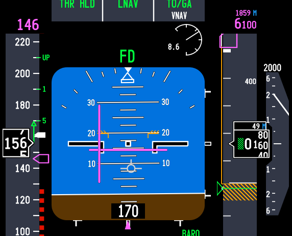
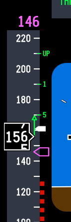
There are three visual aids, located on speed tape on the Primary Flight Display (PFD), that can be used to help determine the correct time to retract the flaps:

  • The Flap Manoeuvring Speed bug;

  • The Speed Trend Vector arrow; and,

  • The V2+15 KIAS white carrot bug.

Flap Manoeuvring Speed Bug

The Flap Manoeuvring Speed bug is a green-coloured line. The bug indicates when to retract the current flaps detente.  For example, when the aircraft's airspeed matches or passes through the flaps 5 designation you would select flaps 5 to flaps 1.  Then, when the airspeed passes through the flaps 1 position you would select flaps 1 to flaps UP.

Another way to think of the flap manoeuvring speed is it is the minimum airspeed that the flaps can be retracted.

Speed Trend Vector Arrow (STV)

Located on the speed tape on the PFD is a vertical arrow called a Speed Trend Vector (STV).  The Speed Trend Vector will display a green-coloured upwards, neutral or downwards facing arrow. 

During climb-out, the Speed Trend Vector arrowhead can be used to determine how long it will take for the aircraft, at the current thrust setting and wind conditions, to reach the speed that the arrowhead is pointing at (usually around 10 seconds).  Therefore, when the upward arrowhead reaches the flap manoeuvring speed bug, the aircraft will pass through this flaps détente in approximately 10 seconds.

The Speed Trend Vector also aids in determining if the speed of the aircraft is increasing, is stable, or is decreasing. This is important, as initial flap retraction should only occur when the speed of the aircraft is increasing. If the STV displays a stable or negative facing arrow, the initial retraction of flaps should be delayed.

Importantly, the Speed Trend Vector is 'live', meaning that the computer takes into account the aircraft's airspeed, vertical speed, and wind direction prior to displaying the vector on the PFD.  The Speed Trend Vector is also a useful tool during descent and on approach, when managing airspeed is critical.

White Carrot Indicator Bug

Located on the speed tape on the PFD is a white-coloured marker called a carrot (the carrot looks more like a sideways facing arrow).  The position of the carrot indicates V2+15 or V2+20 KIAS (the + speed is determined by the engine type and can be set to +15 or +20 in the ProSim IOS).

The carrot is a visual aid to indicate when the aircraft's airspeed has reached V2+15 KIAS.  This is the minimum speed at which the flaps can start to be retracted. 

The carrot is automatically removed from the display after the first flap retraction has occurred.

Flap Retraction - VNAV and Level Change Takeoff (V2+15)

VNAV Takeoff

  • At 400 ft AGL, VNAV becomes active.

  • At Acceleration Height (1000–1500 ft AGL), VNAV commands a pitch reduction to accelerate.

  • Flap retraction begins at V2+15 and continues as each flap manoeuvre speed is reached.

  • The autopilot can be engaged after 400 ft AGL for smoother transitions.

Level Change (LVL CHG) Takeoff

  • Used when VNAV is not armed or not preferred.

  • At Acceleration Height, the pilot selects flaps up speed in the MCP and engages LVL CHG.

  • Aircraft pitches to maintain that speed, allowing flap retraction as each flap manoeuvring speed is reached.

  • Autopilot is selected when flaps are fully retracted (discretion of pilot in command).

The key consideration is that a Level Change takeoff requires more manual monitoring of airspeed and pitch, in contrast to a VNAV takeoff which is smoother for flap retraction.

Flap Retraction Example (V2+15)

During a standard flaps 5 takeoff the following flaps retraction schedule should be followed:

When the airspeed reaches V2+15 or above or matches the Flap Manoeuvring Speed bug, and the Speed Trend Vector shows a positive arrow display, the first flaps retraction can occur (flaps 5 to flaps 1). When the airspeed matches the position of flaps 1, the flaps can be retracted to the UP position.

IMPORTANT POINT:

  • Be aware that the flaps do not retract instantly; depending upon the flap detente, the time it takes for the flaps to retract can be a few seconds. This should be taken into consideration, especially during a higher flap takeoff such as a flaps 25 takeoff.

Recommendations (Transition From Hand Flying To Automated Flight)

The transition from hand flying the aircraft to automated flight should be as seamless as possible.  To reduce the likelihood of unwanted or unexpected deviations from the desired flight path (for example, excessive attitude and/or an increase or decrease in thrust):

  1. The takeoff trim should be correct for the aircraft’s weight;

  2. The aircraft must have adequate airspeed;

  3. The flaps should be retracted as per the flap manoeuvring speed;

  4. The autopilot should not be engaged below 400 feet AGL;

  5. The autopilot should not be engaged before flap retraction is complete (1), and,

  6. The autopilot should be engaged only when the aircraft is in trim (neutral stick).

If these recommendations are followed, the transition from manual to automated flight will be barely discernible.

(1)  Technically speaking, the 737-800 can have the autopilot engaged before flaps retraction, however, best practice is to engage the autopilot after the flaps have been retracted.  Many operators stress that the flaps must be retracted prior to engaging the autopilot.  This said, ultimately it is at the discretion of the pilot in command.

Important Points:

  • The minimum altitude for initial flap retraction is 400 feet AGL, but most flight crews will begin to retract flaps at V2+15/20 KIAS or when the aircraft reaches Acceleration Height.

  • Flap retraction should be initiated upon reaching the manoeuvring speed for the current flap setting with the aircraft's airspeed increasing, unless the airspeed is above V2+15/20 KIAS and increasing; whereby, the first flap retraction can occur.

  • The white carrot is a handy reference to V2+15/+20 KIAS.

Autothrottle Disconnect Before Autopilot Disconnect

I also want to mention one further caveat when transitioning from automated to manual flight, and this involves the disconnection of the autopilot and autothrottle - not so much during a takeoff but at other stages during the flight.

Whenever hand flying the aircraft, the autopilot and autothrottle must not be engaged, but which do you disengage first - autopilot or autothrottle. Best practice is to always disconnect the autothrottle before the autopilot. The reason being is that the aircraft ‘s autothrottle system will respond more quickly than the autopilot (the last thing you need is for the autothrottle to spool after disconnecting the autopilot). Furthermore, do not disconnect both in rapid fire - take your time and wait a second between disconnecting the autothrottle followed by the autopilot. This enables a more seamless transition to occur.

Additional Information:

Final Call

My friend had an intense few minutes as the automated system attempted to fly the parameters that had been entered into the FMC and establish flight conditions based on the aircraft's configuration - a task made more difficult by the fact that the stick shaker was active and the altitude was below 600 feet.

Although this occurred in a simulator, it underscores an important lesson: preparation is key to a successful flight. There must be a clear plan for when specific actions will take place, and shortcuts must be avoided. Had my friend set the correct takeoff trim based on the aircraft's weight and refrained from engaging the autopilot while the aircraft was still in an unclean configuration at a low airspeed, the stick shaker probably would not have been triggered, and the flight could have been recovered. Unfortunately, with such low altitude, there was no margin for error - and the result was a simulator reset.

Video

The video shows the various displays discussed. The take off was a VNAV takeoff and the autopilot was engaged immediately after the flaps were fully retracted.


Primary Flight Display showing various takeoff guides discussed in main article


Flap retraction (courtesy U-Tube). This is not from flaps-2-approach


Image Gallery

Acronyms

AGL - Above Ground Level

Attitude - The orientation of the aircraft relative to the horizon, typically described in terms of pitch (nose up/down), roll (bank left/right), and yaw (nose left/right).

KIAS - knots indicated airspeed. 

Changing-out Potentiometers - UniMeasure LX-PA Series Position Transducer

UniMeasure LX-PA string potentiometer secured to a bespoke L-bracket and mounted on a board beneath the platform. The string connects with the rudder assembly

Potentiometers are arguably one of the most critical components in a flight simulator.  Without a potentiometer, the accurate calibration of the flight controls (or any other device) isn’t possible.  

Over the years, I have used a number of different types of potentiometers, beginning with inexpensive Chinese-made linear and rotary types, and later progressing to Bourns rotary potentiometers paired with fabricated strings. At one point, I also trialled a commercial CALTSensoR string potentiometer.

When a string broke on the potentiometer that controlled the elevator, I decided that, rather than repair the string, I would replace all the potentiometers used to calibrate the flight controls (ailerons, elevator and rudder).

Instead of using the CALTSensoR model mentioned earlier, I opted to upgrade all the potentiometers to string potentiometers made by UniMeasure.

UniMeasure Potentiometers (Transducers)

UniMeasure, an American company based in Oregon, specialises in manufacturing position and velocity sensors for the medical, defence, and industrial sectors. Renowned for their high-quality components, UniMeasure potentiometers adhere to Mil-Spec and IP/NEMA standards, and they’ve been an industry leader since 1987.

After reviewing the different types of potentiometers, I ordered three LX-PA series position transducers.

Is it a Potentiometer or a Transducer

The terms potentiometer and transducer are often used interchangeably to describe the same component.  Although the use of these terms is acceptable, there are subtle differences between a potentiometer and a transducer.  The primary difference being that a transducer will convert the input received into a different output, whereas a potentiometer will only detect and measure the movement of an object (for example, a control arm).

LX-PA Series Position Transducer

The LX-PA series transducer consists of three main parts:

  1. A potentiometer – a Bourns rotary potentiometer (type 3545).

  2. A retractable mechanism – a reel so that the string can extend and retract.

  3. A string – a 0.4 mm jacketed stainless steel length of wire with a stainless steel eyelet.

These components are housed in a compact, durable ABS plastic casing.  The small size and lightweight design make the LX-PA ideal to use in relatively tight spaces.

How the LX-PA Series Transducer Works

Before installing and using a string potentiometer, it’s important to have an understanding of how a potentiometer works.

A potentiometer is a resistive-type transducer, that converts linear or angular displacement into a variable voltage output signal. This process occurs when a sliding contact (known as the wiper) moves along the surface of a resistive element, typically a carbon track.

The potentiometer is securely mounted at a fixed position, with its string attached to a movable object. As the object moves, the string extends, rotating the internal sensing device to produce an electrical output proportional to the object’s position or velocity.  An internal spring maintains string tension and serves as the retraction mechanism for the string.

Electrical Output

The electrical output that is produced by the potentiometer is less effective as the string reaches its fully retracted or extended position, meaning that calibration is not as effective towards each end of the string’s length.  Therefore, it is important to take into consideration the length of the potentiometer’s string. 

LX-PA string potentiometer mounted to L-bracket and secured to platform. The string can be seen in a direct line connecting with the ailerons

Measuring the Throw

To ensure optimal results, measure the throw from the mounting point of the potentiometer to where the end of the string is to be attached to the moveable object, then add a few inches to your measurement.  This is the length of string that should be used with the potentiometer. 

If the string is too long or short, you will be calibrating the end points of the string, which is not as accurate as if you had calibrated the central portion of the string.  Additionally, if the string is too long and near its end point, excessive tension on the reel’s retractable mechanism may occur, leading to premature loss of tension.

An average rule of thumb is to try and use two thirds of the distance (throw), or predominately the central portion of the string, as this is where the most effective output signal is found, and where the best calibration can occur. 

When you order a potentiometer from UniMeasure, you inform the technician of the length of the string required and the potentiometer is made to your specification.

It is important to note that potentiometers are passive components, meaning they do not necessitate a power supply or additional circuitry to operate.

Important Point:

  • The length of the string is important. However, do not be overly pedantic about obtaining the exact measurement. The calibration will still be accurate provided you allow a few extra inches (a ‘dead zone’) at each end of the string, and primarily use the central portion of the string.

Splitter ring attached to tilt elevator mechanism of the flight controls with the lobster clasp connected

Installation and Attachment

Although the LX-PA series is not the smallest potentiometer UniMeasure manufactures, it is small enough to be mounted in all but the tightest areas. 

The potentiometer requires a secure attachment point, and a bracket is the easiest way to do this.  UniMeasure sell a dedicated bracket, however, I decided to fabricate my own L-bracket.  The LX-PA has two 5 mm diameter holes in the body of the potentiometer and can be secured to the L-bracket by a suitable bolt and nut.  The position of the holes in the main body enable the potentiometer to be mounted a number of ways (up, down, inverted, sideways, flat, etc).

To attach the string to the moveable object (aileron, elevator rudder, etc) requires that there be a stable attachment point on the object.  The string does not have to be permanently attached to the object (although you can do this). 

Splitter Ring and Lobster Clasp

My preferred method is to attach to the eyelet of the string to a one way clasp (often called a lobster clasp).  This clasp is attached to a splitter ring (curtain-rail ring) that is attached to the object. To enable attachment of the splitter ring, I have drilled a hole into a moveable part of the flight control mechanism.

The advantage of using a lobster clasp is the string can easily be disconnected; for example, when servicing is required.

Line Pull

The direction of the line pull is important and UniMeasure recommend to not exceed 2 degrees in any direction.  If a further offset is required, a stand-off, such as a fly wheel, will need to be purchased or fabricated.   

Exceeding the recommended offset will more than likely shorten the life the string, because the string would retract into the spool at an angle, causing undue wear and tear with a potential loss of accuracy.

Important Points:

  • For the string to be effective, the string must be under tension.

  • Do not extend the string to its full length, as this can damage the reel mechanism.

  • Maintain lateral or vertical alignment within 2 degrees to avoid unnecessary wear on the reel.

  • Do not allow the string to come into contact with objects along its path.

Connection and Calibration

It is not difficult to connect the UniMeasure potentiometer to the computer.

The wires from the potentiometer are connected to the appropriate input on a joystick interface card, such as a Leo Bodnar BU0836A or BU0836X joystick card.  Previously I used the former, but changed-out to the larger BU0836X card as it was easier to connect the wires to the card. 

One difference between UniMeasure potentiometers and others is that the UniMeasure has one additional wire to the standard three.  The forth wire is a shield wire (naked coiled wire). 

What is a Shield Wire

A shield wire provides electromagnetic compatibility protection and serves two purposes:

  1. It prevents interfering signals from the inside of the cable from reaching the outside and being disturbed to other cables and electrical devices; and.

  2. It ensures that external interference does not reach the inside of the cable and potentiometer.

Shield wires are often connected when a potentiometer is used in a high-accuracy setting such as in medical scanners.  However, it is debatable if there is any positive benefit in using a shield wire in a flight simulator environment. If the shield wire is used, the wire should be connected to ground for optimal results.

The other three wires from the potentiometer: common (black wire), +5 Volts (red wire) and the output (white wire) connect to the respective points in the BU0836X card.

All the wires have been professionally soldered to the potentiometer’s terminals, and are insulated with PVC, except for the last 4 cm which are bare. 

Calibration of the potentiometer requires initial registration in Windows using the joystick controller interface (type JOY in the computer’s search bar).  After this has been completed, calibration can be done either directly in flight simulator, ProSim737 or FSUIPC.

Protection from Dust and Water

The LX-PA series is not fully dust-proof or waterproof.  Whilst the potentiometer itself is dust-proof due to its enclosed design, dust can accumulate where the string enters the reel.  This said, unless the string is located in a particularly dusty environment, dust ingress should not occur.  If dust does present a problem, the string can be cleaned using high-pressure air, alcohol, or a circuit-board cleaner. 

If the environment is particularly dusty or damp, an alternative UniMeasure series potentiometer should be considered that has better dust-proofing.

Interestingly, the method used by UniMeasure to dust-proof their potentiometers (not the LX-PA series) involves the use of two curtains that are installed where the string slides into the mechanism.  These curtains when dirty, can be removed for cleaning or can be replaced. 

To protect the potentiometer’s terminals where the wires are soldered, UniMeasure offers a removable cover.  The cover pushes over the cylindrical part of the potentiometer and is secured by three small screws.  The cover ensures that nothing will damage the terminals.  The cover is a very good fit and it is very unlikely that any dust or moisture will enter behind the cover into the potentiometer

Durability and Lifespan

The body of the LX-PA series is made from ABS plastic, and when the potentiometer is fitted with the protective cover (discussed earlier) makes for a relativity robust unit; an odd light knock here and there is not going to damage the potentiometer.

The LX-PA transducer has an impressive lifespan:

  • The potentiometer is rated for 2.5 million cycles, while

  • The lifespan of the reel and string varies and is dependent upon length of the string:

    • Up to 4.7 inches - 1,000,000 cycles.

    • 10–25 inches - 250,000 cycles.

Accuracy and User Experience

Although the LX-PA transducer uses a standard Bourns potentiometer, the accuracy when calibrating and using the potentiometer comes more from the build quality of the string and how it retracts into the reel, than the actual potentiometer. 

The slightest movement of the yoke, elevator or rudder is reflected in the avionics software and there is no noticeable acceleration or lag as the string moves in and out of the of the reel.   In comparison to its closest rival, the CALTSensoR potentiometer, the UniMeasure string’s movement is far more smooth and has no apparent binding.

Calibrating flight controls to ensure optimal accuracy has always been finicky, and considerable time can be wasted attempting to achieve optimal results. Calibration of the LX-PA potentiometers was a breeze, and since using these potentiometers I have noticed that control of the aircraft, especially during crosswind landings, is far more easy than what it previously was.

Additional Information

Final Call

The LX-PA series transducer is a premium potentiometer that combines a high-quality Bourns rotary potentiometer with a durable, precision-engineered retractable reel and string.  With proper calibration, it captures even the slightest movement with impressive accuracy, making it a perfect choice to connect to the flight controls.

Below: UniMeasure LX-PA series potentiometer

Changing-out Joystick Cards - Leo Bodnar BU0836X Joystick Card

Leo Bodnar BU0836X joystick card and enclosure

Most flight simulators require regular maintenance to ensure that all systems function correctly. During a routine overhaul, which included replacing the potentiometers that are used to calibrate the flight controls, it was discovered that a Leo Bodnar joystick card had been damaged. Rather than replace the card with the same type (BU0836A), I decided to change-out to a Leo Bodnar BU0836X joystick interface card and protect it with a dedicated metal enclosure. 

I will not duplicate the detailed information that has already been written about the BU0836X on the Leo Bodnar website.   Rather, I will examine the advantages of using this particular card. 

The card and its protective enclosure can be purchased separately from Leo Bodnar Electronics in the United Kingdom. 

BU0836A and BU0836X Joystick Card

The BU0836X 12-bit joystick interface card has been available for some time and is very similar to the BU0836A joystick card; the latter being the mainstay for interfacing various hardware.  Both cards enable calibration of the joystick axes used for controls such as the ailerons, elevator, rudder, and the steering tiller, as well as interfacing with a various simulator buttons and knobs. 

Key Advantages 

The primary advantage of the larger BU0836X card, aside from its additional inputs and outputs, is that it does not use the JR connectors found on the BU0836A card.  JR connectors can be fiddly, prone to breaking (if not connected properly), and may become loose unless soldered directly to the card’s pins.

Over the years, I and cannot recall how many times a JR connector had worked its way loose from the vibration generated by the trim wheels rotating, and depending on the location of the card, a repair can be time consuming.

In contrast to using JR connectors, the BU0836X features push-to-secure connectors. This design allows wires between the gauge of 24-20 AWG (stripped to 9mm) to be easily inserted into the correct terminals and locked in place without requiring screws, solder, or JR connectors.  It’s only a matter of pushing the tab on the card inwards and inserting the wire into the hole. 

The push-to-secure design not only simplifies connection but also makes it easier to replace components like potentiometers or other hardware devices when necessary.  Additionally, the terminal bar is colour-coded with clearly printed labels, making identification straightforward, thereby reducing the risk of wiring errors.

The card has 8 analogue inputs (potentiometers, knobs), 32 inputs (button, switches) and 1 joystick HAT controller.

I find that working with a slightly larger card is much easier than its smaller sister, although an obvious downfall is the space required to mount the BU0836X card. I also like the fact that the card is made in the United Kingdom; therefore, production inconsistencies that occur with many less expensive Chinese cards is not as prevalent.

BU0836X Protection 

The card can be mounted on a base plate using standoffs and screws.  However, as with any hardware component, it is susceptible to damage from movement, accidental knocks, or falling objects - especially during maintenance (screwdrivers, pliers, eye glasses, coffee cups, mobile phones, i-pads, etc). 

To address this, Leo Bodnar offers a protective enclosure that has been specifically designed for the BU0836X and BU0836A cards respectively. The enclosure comprises two pieces of metal with the inner piece (called the slider) designed to slide into and out of the outer casing.  The card clips firmly into the inner slider and a small hex screw fastens the slider into the outer casing.  Realistically, the hex screw is overkill as the inner slider fits quite firmly, and I very much doubt that the slider will accidentally slide out of the outer casing.  The enclosure can then be attached to a base plate using four screws.

Once secured inside the enclosure, the card remains firmly in place and does not move or wiggle, ensuring excellent stability. This setup provides robust protection against physical damage while keeping the terminals fully accessible.

The enclosure has been well designed, is fabricated from metal, powder coated, and coloured black.

Additional Considerations 

Despite the protective enclosure, the wiring remains exposed to the environment, leaving it vulnerable to dust and dirt accumulation.  If this is a concern, a simple and effective solution is to fabricate a small plastic cover to shield the card and its wiring.  A repurposed plastic takeaway container works well for this purpose, providing an inexpensive and practical way to keep the card clean and secure. 

Calibration

The BU0836X card is calibrated in the same way as the BU0836A card: initial registration in windows using the Game Controller (type JOY in the computer’s search bar) and then calibration in either flight simulator, ProSim737 or FSUIPC.

Final Call

The BU0836X card stands out for its well-thought-out design. Its larger size makes terminal identification and access easier, while the push-to-secure connectors provide reliable, solder-free connections.  Although its size could be a disadvantage in tighter spaces, it works well for most applications where space constraints are not a concern.  Additionally, the optional metal enclosure offers protection against physical damage, enhancing the card’s long-term durability.

For further information detailing how to use the BU086X joystick card.

  • This article is not endorsed by Leo Bodnar Electronics. Furthermore, I paid full price for the products discussed. 

Below: Gallery showing photographs of the BU0836X and BU0836A joystick cards and enclosures.

Batch Files to Open and Close Flight Simulator

Opening and closing the various files and ancillary programs to operate a flight simulator can be onerous and time consuming.  While there have been several programs released that enable you to launch flight simulator with a press of a key, they seldom work with complicated platforms such as flight decks. 

One of the most commonly used methods to open files and programs is to use the start menu within Windows.  However, this is not without it’s shortcomings, and specialist knowledge is required.  An easy and trouble free approach is to use batch files.

What is a Batch File

A batch file is a script file that stores commands to be executed in a serial order.  It helps automate routine tasks without requiring user input or intervention. Some common applications of batch files include loading programs, running multiple processes or performing repetitive actions in a sequence in the system.

Also known as a batch job, a batch file is a text file created in Notepad or some other text editor.  A batch file bundles or packages a set of commands into a single file in serial order.  Without a batch file these commands would have to be presented one at a time to the system from a keyboard.

Usually, a batch file is created for command sequences when a user has a repetitive need.  A command-line interpreter takes the file as an input and executes the commands in the given order.  A batch file eliminates the need to retype commands, which saves the user time and helps to avoid mistakes.  It is also useful to simplify complex processes.

Windows usually uses the .bat extension for batch files.

Whilst there are several methods that can be used to write a batch file, I have found that the examples below operate flawlessly.

Writing a Batch File

It's a simple process to write a batch file. 

Prior to beginning, it’s wise to think about the order you want the programs to open, and whether you want a pause between opening particular files and programs.  While a pause is probably not necessary, it’s a good idea as it allows a file or program to complete its opening sequence, prior to the next file or program opening.

When you have completed writing the batch file in notepad save the file with a .bat extension.  To test the batch file double click on the saved .bat extension.

Although others will disagree, I always open the MSFS-2020 or P3d and allow the program to settle before opening any batch file or other programs.

The following examples of batch files are user-specific.  You will need to substitute the file structure with the file structure you are using.

Opening Files and Programs

  • An example of a batch file to open the main flight simulator computer (server).

@Echo  off

//Alpha Main Server Computer (ALPHA-SERVER-P3)  - 09:38 - 25/08/2023

//ProSim738 V3

//ProSim Ancillary Programs

start /d "D:\Flight Simulator Files\SimStacks October 2021\SimStackSwitchv702" Switch.jar

Timeout 0.5

start /d "D:\Flight Simulator Files\FS Set Volume" FSSetvol.exe

Timeout 0.5

start /d "D:\Flight Simulator Files\SimSounds 4.0" SimSounds.exe

Timeout 1

start /d "D:\REX WeatherForce.exe

//ProSim Main Programs

start /d "D:\Flight Simulator Files\ProSim738 V3\ProSimAudio" ProsimAudio.exe

Timeout 1

start /d "D:\Flight Simulator Files\ProSim738 V3\ProSimB738" ProSimB738.exe

An example of a batch file to open the avionics suite on the second computer (client 1).

@Echo off

//Client 1 - ProSim-AR B738 Avionics Suite V3    14:07 5/09/20

//PS738 V3

//Ancillary Programs

start /d "C:\Users\user name\Documents\FSF\Programs\MSFS WideFS7" kilo

start /d "C:\Users\user name\Documents\FSF\Programs\Landing Rate Monitor" LRM.exe

start /d "C:\Users\user name\Documents\FSF\Programs\SimSounds 4.0" SimSounds.exe

//Hardware Connector

start /d "C:\Users\user name\Documents\FSF\ProSim738 V3\ProSimB738-HardwareConnector" ProSimB738-HardwareConnector.exe

//ProSim737 Displays and Indicators

start /d "C:\Users\user name\Documents\FSF\ProSim738 V3\Displays\CAPT PFD" ProsimDisplay.exe

start /d "C:\Users\user name\Documents\FSF\ProSim738 V3\Displays\CAPT ND" ProsimDisplay.exe

start /d "C:\Users\user name\Documents\FSF\ProSim738 V3\Displays\FO PFD" ProsimDisplay.exe

start /d "C:\Users\user name\Documents\FSF\ProSim738 V3\Displays\FO ND" ProsimDisplay.ex

start /d "C:\Users\user name\Documents\FSF\ProSim738 V3\Displays\EICAS" ProsimDisplay.exe

start /d "C:\Users\user name\Documents\FSF\ProSim738 V3\Displays\FLAPS" ProsimDisplay.exe

start /d "C:\Users\user name\Documents\FSF\ProSim738 V3\PS738ChronoCaptain" ProsimDisplay.exe

Timeout 3

start /d "C:\Users\user name\Documents\FSF\ProSim738 V3\ProSimIOS" ProSimIOS.exe

Closing Files and Programs

Likewise, you can also use a batch file to close files and programs sequentially or simultaneously (kill all).

An example of a batch file used to close programs on the main flight simulation computer (server).

@Echo off

//Alpha Main Server Computer (ALPHA-SERVER-P3)  - 09:38 - 25/08/2023

//ProSim738 V3 – closure batch

taskkill /IM wideclient.exe

Timeout  2

taskkill /IM ProSimAudio.exe

Timeout  1

taskkill /IM PMSounds.exe

Timeout 1

taskkill /IM Prosim737.exe

Timeout  4

taskkill /IM fs2020.exe

  • im specifies the image name of the process to be terminated (for example, PMSounds.exe or ProSim737.exe).

  • @echo on/off defines whether a name or message will be displayed on the console.  It’s also used for other tasks such a script troubleshooting.  I have used it in my batch files because I was told it was a good idea to do so, but if you don’t use the @echo command the batch file still works.  If you do use the @echo command I recommend you use @echo off as this will turn off this feature.

  • The // syntax is used to stop the line from being read by the batch file. 

In the examples, the Taskkill command has been used to close the programs.  Taskkill will cause the program to terminate gracefully, asking for confirmation if there are unsaved changes.

To forcefully kill a process, add the /F option to the command line. Be careful with the /F option as it will terminate all matching processes without confirmation.

An example using the /F command is: Taskkill /F /IM ProSimAudio.exe.

There is debate in the computer community to the validity of closing files and programs simultaneously, as ‘killing a program’ may not allow the program enough time to save information it may be saving during the closure process.

For this reason, I'm hesitant to close flight simulator (or other programs) using a closure batch file without a timeout or delay sequence.  Needless to say, it's an easy process to configure a time delay into a batch file to create a delay before closing each program.

Timeouts

Depending upon your computer specifications, some programs may open and close at differing speeds.  If you want a program is open or close before the next program, then a delay sequence will need to be timed into your batch file. 

The timeout command is used to trigger a delay between the programs, enabling any read/write requirements to occur prior to the next program beginning it closure routine.  The numeral denotes seconds or part thereof. 

Streamlining

Once you have created and saved the batch file, a suggestion is to create a shortcut to the file.  Doing this will enable you to make changes to the batch file such as how the file is executed (minimised or maximised), the position on the screen, colour and font style used, and whether to use an icon for easy identification.  Additionally, by creating a shortcut it enables you to place the shortcut on your task bar.

To create a shortcut, right click the batch file and save as a shortcut.

Using Batch Files and ProSim IOS

ProSim-TS IOS screen in opened to network page.  Rather than explain everything, copy the details and use trial and error to achieve your desired result

If you are using multiple computers, you may want to use the ProSim Instructor Operator Station (IOS) to trigger the opening or closure of programs (via the batch file).  When IOS is configured correctly, you will be able to open and close a batch file on one or more networked computers from one computer screen.

To configure IOS, open the network tab, select add a new action or type and select start program.  In the path to executable file on client box type the file address of the batch opening file.  Choose the start option you prefer and ensure that enabled in checked.

To close your programs, open a second action and type in to the path to executable on client box the file address of the batch closure file.

The accompanying image should be self explanatory.

There are other ways to do this, however, this method is probably the simplest.

Caveat

I am not computer technician.  I have used batch files similar to the examples shown for many years without issues.

Final Call

Batch files are but one way to minimise workload and automate the opening and closure of ancillary programs that are used with flight simulator.  The use of IOS to trigger batch files also enables the user to open and close ancillary programs from the one computer screen (instructor station).

Changing Sound in the ProSim 737 Aircraft with MSFS-2020

Many enthusiasts like to change the sound files that come with ProSim-TS 737 aircraft.  In my simulator I use an assortment of sounds including those from ProSim, PMDG, the immersion CFM engine sound pack, and audio recordings that have been made from the real aircraft.

Read More