
Digital Chronograph Running ProSim737 Software
/
The Main Instrument Panel (MIP), unless a special order is made, usually will not include a chronograph. Depending upon the MIP manufacturer, the MIP may have a cut out for the chronograph, a facsimile of a chronograph or just a bezel.
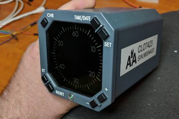
LEFT: OEM chronograph used by America Airlines. Although nothing beats an OEM item, in this case conversion is difficult; therefore; a reproduction chronograph was more cost effective. Image courtesy of Micks737.
The Next Generation aircraft mostly use digital chronographs. The classic series airframes usually use (unless retrofitted) mechanical chronographs.
After Market Chronograph
There are several after-market chronographs that can be purchased. SISMO Solicones produce a mechanical type that replicates the real world counterpart quite well, despite the awful orange-coloured backlighting. Flight Illusion produces a quality instrument as does Flight Deck Solutions (FDS). FDS replicate the digital chronograph.
Chronographs are manufactured by several companies and not every chronograph looks identical, although their functionality is. There are a few different styles available to an airline. The main difference is in the number and shape of the buttons; round or rectangular.
No matter which type you decide, be prepared to shell out 250 plus Euro per chronograph; for an item rarely used it's quite a financial outlay.
Converting OEM Chronograph
Converting an OEM B737 mechanical chronometer is a valid option and the process of conversion is relatively straightforward. However, finding a mechanical chronograph in operational order is difficult, as airlines frequently keep chronographs in service for as long as possible. Converting a digital chronograph is also an option, however, the initial price of the item and then conversion make this an expensive exercise. Add to this the fact that converting the chronograph, due to its internal digital electronics is very difficult (even if you use ARINC 429 protocol).
Another option is to use the virtual chronometer (Sim Avionics and ProSim737) and fabricate a reproduction bezel that overlays a small LCD screen.
ProSim737 Virtual Chronograph
Screen capture of ProSim737 chronograph. ProSim737 have a Chronograph that can be used for the Captain and First Officer side of the MIP. There are seevral version of the display that can be used
ProSim737 as part of their avionics suite have available a virtual chronometer.
The display used by ProSim737 is very crisp, the size is accurate (1:1 ratio), and the software allows complete functionality of the chronograph.
To use the virtual version a small computer screen is needed on which is displayed the virtual chronograph.
Chronograph
A friend of mine indicated that he wanted to make a chronograph for the simulator and use the virtual ProSim737 display. He also wanted to incorporate the four setting buttons and have them fully functional.
The components needed to complete the project are:
A small TFT LCD screen (purchased from e-bay);
A standard Pokey interface card;
Several LEDS; and,
Four small tactile switches and electrical wire.
I currently use an Main Instrument Panel (MIP) fabricated by Flight deck Solutions (FDS). Therefore, the chronograph bezel used in this project was that supplied by FDS.
The screen used was 5.0" TFT LCD Module with a Dual AV / VGA Board 800x480 with a 40 Pin LED Backlight.
The screen was small enough that it just covered the circular hole of the cut out in the FDS MIP. The TFT LCD screen uses a standard VGA connector cable, 12 Volt power supply and a USB cable to connect the POKEY card to the computer.
The holes in the box provide ventilation for the Pokeys card. The only portion of the box that is visible from the front of the MIP is the bezel and four buttons
Two-part Fabrication
FDS supply with their MIP a bezel with four solid plastic but non-functional buttons. The bezel does not support direct backlighting, nor does it have enough space for tactile switches or wiring.
Therefore, the FDS bezel must be modified to accommodate the wiring for the switches and LED illuminated backlighting. The easiest way to approach this modification is to use a Dremel rotary tool with a 9902 Tungsten Carbide Cutter.
Place the bezel on a hard surface using a towel to avoid scratching and damaging the bezel. Then, with 'surgical' accuracy and steady hands carve out several channels (groves) at the rear of the bezel. The channels enable placement of the miniature tactile switches, small LEDS and wiring.
Space is at a premium, and to gain addition real estate, the LEDS were shaved to remove excess material. This enabled the LEDS to fit into the excavated groove on the bezel. Be very careful when using the carbide cutter to not punch out onto the other side of the bezel.
The four solid plastic front buttons on the bezel are carefully removed and small tactile switches attached (glued) to the rear of each of the buttons. 26/28 AWG wire is used to connect the tactile switches (using common ground leads) to a PoKeys interface card.
The box is not seen as it's attached to the rear of the MIP. My friend's humour - several warning signs suggesting that I not tamper with his creation :)
Box Fabrication
A small box needs to be fabricated to house the Pokey card. The size of the box is controlled by the size of interface card used and the length and width of the LCD screen.
A box is not required, however, it's a good idea as it illuminates the need to seal the LCD screen to illuminate dust ingress between the screen and overlying glass in the bezel.
The material used to fabricate the box is plastic signage card (corflute); real estate agencies often use this type of sign. The main advantage of this material is that it’s not difficult to find, is light in weight, and it's easy to cut, bend, and glue together with a glue gun.
After the Pokey card is installed to the inside of the box, and the LCD screen attached to the front edge, the bezel needs to be secured to the front of the LCD screen. The best method to attach the screen and bezel is to use either glue or tape.
A hole will need to be made in the rear of the box to enable the fitment of the USB and VGA connectors. Small holes punched into the side of the container ensure the LCD screen and PoKeys card do not overheat. If you're concerned about heat buildup, a small computer style fan can easily be added to the box, but this does add complexity and is not necessary. To conform to standard colours, the box is painted in Boeing grey.
LED Backlighting
Careful examination of the backlighting will show that the light coverage is not quite 100%. There are two reasons as for this.
(i) There is limited space behind the bezel to accommodate the wiring and the LEDS; and,
(ii) The material that FDS has used to construct the bezel is opaque. The only way to alleviate this is to replace the stock bezel with another made from a transparent material.
Important Point:
If you want to try and replicate the digital OEM chronograph as closely as possible, that the OEM version does not use backlighting. Illumination of the front of the chronograph is by the MIP lighting.
Potential Problem
Depending on the MIP being used, there maybe space constraints that do not allow a 5 inch screen to be easily positioned. If you're forced to use a smaller screen, the outcome will be that you may see the screen edges within the bezel. For the most part this is not an issue, if you ensure the desktop display is set to black. Remember, you are looking at the chronograph from a set distance (from the pilot seat) and not close up.
ProSim737 Virtual Chronograph (position and set-up)
This task is straightforward and follows the same method used to install and position the PFD, ND and EICAS displays.
Open ProSim737’s avionics suite and select the virtual chronograph from the static gauges: resize and position the display to ensure the chronograph conforms to the size of the bezel. To configure the buttons on the bezel, so that ProSim737 recognizes them with the correct function, open the ProSim737 configuration screen and configure the appropriate buttons from the switches menu (config/switches).
The four functions the buttons are responsible for are:
(i) Chronograph start;
(ii) Set time and date;
(iii) Expired Time (ET) and Reset; and,
(iv) +- selection
NOTE: The above functions differ slightly between the panel and the virtual chronograph in use.
Chronograph Operation and Additional Configuration
Captain-side CLOCK start button. Connection between the clock button and the CHR button is made in the assignments page in ProSim737 (FDS MIP)
The chronograph can be initiated (started) by either depressing the CHR button on the top left of the clock, or by depressing the CLOCK button located on the glarewing of the MIP.
Configuration
Connecting the CLOCK button to the chronograph start (CHR) function is straightforward.
Connect the two wires from the Captain-side clock button to the appropriate interface card and configure in the switches tab of ProSim737 (config/switches/CAPT CHR).
The same should be done with the First Officer side CLOCK button and chronograph, however, ensure you select the FO CHR function in switches to be done for the First Officer side chronometer if fitted.
If configured correctly, one press of the CLOCK button will start the chronograph, a second press will stop the chronograph, and a third press will reset the chronometer to zero.
After Market Chronograph
For those wanting to use an after market chronograph, SimWorld in Poland and Flight deck Solutions (FDS) in Canada produce high quality chronographs that can be dropped into the MIP with minimal required fabrication.
Video
A short video (filmed at night) showing the new chronograph running the virtual ProSim737 software. Note that the chronograph displas is slightly smaller in the video to what it should be. Adjusting the size of the display is done within the ProSim737 software.
Update
on 2020-06-18 03:27 by FLAPS 2 APPROACH
Another flight deck builder has also constructed a chronograph using similar methods. His chronograph uses a different design that does not use a box.
Update
on 2020-05-23 01:00 by FLAPS 2 APPROACH
In August 2019 this chronometer will be replaced. The replacement will use a similar design, however, will not be encapsulated in a box that fits behind the MIP. The new design will incorporate a å larger 5" TFT LCD screen that will enable more screen real estate for the chronograph. The screen will be mounted directly to the rear of the MIP and the interface card will be adhered to the rear of the screen.
The reason for changing the design is two-fold:
The box is quite large, and the weight (although light weight) is heavy enough to cause the bezel to pull away from the MIP; and,
Accessing the interface card is difficult (as it's inside the box).
An article explaining the process will form a new article. The new chronograph very closely follows the design used by FlightDeck737.BE


