Using OEM Panels in the MIP

OEM Captain-side DU panel.  Note the thick engraving and specialist DZUS fasteners

The introduction of the Boeing 737 Max has meant that many carriers are updating their fleets and retiring earlier production 737 NG airframes.  This has flow on benefits for flight simulator enthusiasts, because more and more OEM NG parts are becoming available due to NG airframes being stripped down and recycled.  

Although some items, such as high-end avionics are priced outside the realm of the average individual, many other parts have become reasonably priced and are often a similar price to the equivalent reproduction part.

This article primarily relates to the panels used in the Main Instrument Panel (MIP), and lower kick stand.  The term panel means the aluminum plate that is secured to the framework of the MIP, and lightplate refers to the engraved plate that is secured to the panel.

Do You Notice The Difference

This is a common question.  The resounding answer is yes – the difference between OEM and reproduction parts can be noticed, especially if you compare the identical parts side by side.  This said, some high-end companies manufacturer panels that are almost indiscernible from the OEM panel.  These panels are bespoke, expensive, and usually are only made to a custom order.  Therefore, it really depends on which manufacturer/company you are comparing the OEM panel against.

Close up detail of OEM lightplate and general purpose knobs

By far the biggest difference between an OEM and reproduction panel, other than appearance, is the tactile feel of a knob, the overall robustness of the panel, and the firmness felt when rotating a commercial-grade switch; the later feels very accurate in its movement. 

There is litle compromise with backlighting as an OEM panel has a consistent colour temperature and intensity without hot and cold spots.  

Using a real panel helps to provide immersion and, as your're using a real aircraft part there is no second-guessing whether the panel is an accurate copy; using an OEM panel is literally 'as real as it gets'.  Furthermore, it’s  environmentally friendly to use second hand parts.  New parts (reproduction or otherwise) are made from  finite resources. 

Limitation

Not every OEM part can work in a home simulator.  For example, the OEM potentiometer responsible for the dimming function in the lower kickstand DU panels cannot be used.  This is because Boeing use a rheostat instead of a potentiometer.  Without going into detail, a rheostat is designed to take into account 115 volts AC commonly used in aircraft.  If using these panels. you will need to change the rheostat to a high-end commercial potentiometer.  

Table 1 outlines 'some' of the main differences between the OEM panels and their reproduction equivalents.

Table 1:  Main differences between OEM and reproduction panels (MIP only).

The information presented in the above table, should not be taken in a way that reflects poorly on the manufacturer of reproduction panels.  There are a few high-end companies whose panels are indiscernible from the real item; it’s the purchaser’s knowledge and the manufacturer’s skill that will define whether a reproduction panel replicates the real item.  ‘Caveat Emptor’should always be at the forefront of any purchase decision.

Potential Problems Using OEM Panels in the MIP

Potential problems often surface when attempting to mate OEM parts to the framework of the MIP.  This is because reproduction MIPs rarely echo the identical dimensions of their OEM counterpart. 

OEM Stand-by instrument panel. Although difficult to see from a picture, the overall robustness of this panel surpasses all but the very best reproductions

It's not possible to document every potential problem, as all reproduction MIPs are slightly different to each other.  However, some issues encountered may be the misalignment of screw holes between the MIP framework and the OEM panel, the inability to use the panel's DZUS fasteners, the panel being too large or too small for the MIP in question, or the open framework structure at the rear of the panel (which incorporates the wiring lume and Canon plugs) interfering with the infrastructure of the reproduction MIP, or the mounting of the computer screens.

In general, OEM panels cannot be mounted to a reproduction MIP without major work being done to the framework of the MIP.   The solution is to use a MIP that has been designed 1:1 with the OEM MIP, or fabricate a MIP in-house to the correct dimensions.

Specifics to the FDS MIP

The MIP used in the simulator is manufactured by Flight Deck Solutions (FDS), and although the MIP is made to a very high quality, the dimensions of the MIP are not 1:1. 

The most problematic issue is that the MIP length is slightly too narrow to enable the OEM panels to be fit correctly to the front of the framework.  For example, the OEM chronograph panel is 1 cm wider than the FDS chronograph panel.  Furthermore, most of the OEM panels (such as the standby instrument, chronograph and landing gear panel) measure 130 mm in height as opposed to the FDS panels that measure 125 mm in height.  This causes problems when trying to line up the bottom of each panel with the bottom of the display bezels. 

The standby instrument panel does fit, however, there is a few centimeters of space between the panel and the adjacent display bezel frame.  In the real aircraft, the display bezel and the edge of the standby instrument panel almost abut one another.  The autobrake panel does fit as do the lower kickstand panels.

FDS use screws to attach their panels to the upper MIP framework, however, OEM panels use DZUS fasteners.  The screw holes on the FDS MIP do not align with the position of the DZUS fasteners in the OEM panel.  The lower MIP panel (kickstand) in the real aircraft also incorporates a DZUS rail to which the panels are attached.  The FDS kickstand does not use a DZUS rail, and screws or reproduction DZUS fasteners are needed to secure the OEM kickstand panels.

The above said, FDS does not state that their MIP is I:1, and when asked will will inform you that OEM panels will not fit their products without considerable fabrication.

DZUS fastener that secures DU panel to the MIP framework

Specialist DZUS Fasteners

The OEM panels used in the upper MIP incorporate into the panel a specialist DZUS fastener.  This fastener is used to tightly secure the panel to the framework of the MIP; screws are not used.  Screws are only used to secure the lightplate to the panel. 

The DZUS fastener is shaped differently to the fasteners used to secure the panels located in the lower kickstand, overhead and center pedestal, and these parts are not interchangeable. 

Reproductions rarely replicate these DZUS fasteners.  However, like many things it's often the small things that make a difference (at least aesthetically).

Rear of OEM Captain-side DU panel.   Note heavy duty rotary switches (Cole & Jaycor brand), neat and sturdy wiring lume, and easy connect Canon plug.  The use of the correct bracket in the panel enables the AFDS unit to fit snugly to the panel.  Note the depth of the external frame which can cause placement issues

Advantages Using OEM Wiring Lume and Canon Plugs

A major plus using any OEM panel is that the part usually includes an expertly-made wiring lume that terminates at Canon plug.    If possible, the original wiring lume should be kept intact and additional wiring should be done from the Canon plug.  It’s very difficult to duplicate the same level of workmanship that Boeing has done in relation to the wiring.  Furthermore, the wire that has been used is high-end aviation grade wire.

OEM landing gear panel. Like any OEM part, the neatness in relation to the wiring is immaculate.  A Canon plug enables the panel to be connected to a lume which then connects with whatever interface card is in use

The Canon plug deserves further mention, as the use of a Canon plug (or any connector for that matter) enables you to easily remove the panel for service work should this be required.  If at all possible, the original Canon plug (and wiring) should be used because it’s neat and tidy and ensures a good connection.  However, if the correct Canon plug cannot be procured then a reproduction plug should be fabricated.  There is nothing worse than having to disconnect wires from an interface card to remove a part.

Configuring an OEM Panel

Configuring an OEM panel to use in flight simulator depends on which panel you are referring to. 

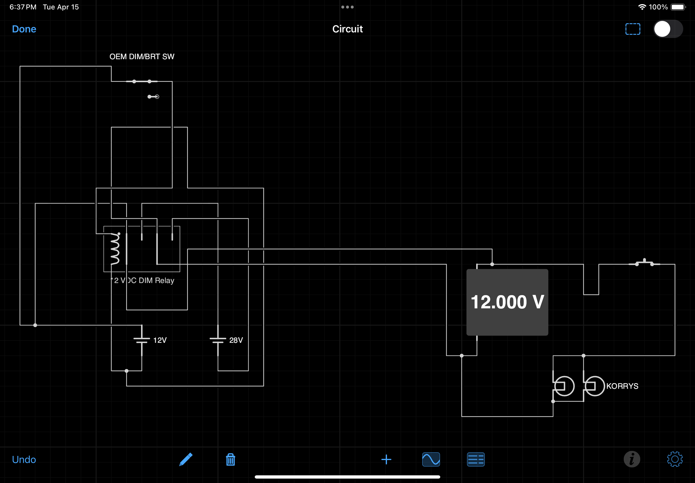
Panels with knobs, toggles and switches are relatively straightforward to interface with a respective interface card (Phidget card, PoKeys card, FDS SYS card or similar).  Determining the pinouts on the Canon plug that control backlighting requires the use of a multimeter, and then connection to a 5 volt power supply.  If the panel includes annunciators (korrys), then these will need to be connected to a 28 volt power supply (using the correct pinouts).

Technology is rarely static, and there are other ways to interface and configure OEM panels.  The ARINC 429 protocol is becomminginceasingly common to use along with specialist interface cards, and these will be discussed in separate articles.

Rear of DU panel showing korry connections and AFDS bracket

The Future

The FDSMIP can, with some work, be modified to mount the OEM panels.  However, an easier option is to find another MIP that has been designed to mount the panels, or fabricate a MIP in-house to OEM dimensions.

Final Call

Aesthetically, nothing beats the use of an OEM panel, and the panels used in the upper MIP and lower kickstand offer little comparison to their reproduction equivalents, with possible exception to bespoke reproductions. By far the biggest challenge is determining the pin-outs for the Canon plug, but once known, configuration using a Phidget or other traditional card is relatively straightforward. 

As straightforward as it may seem, potential problems surface when attempting to mate OEM panels to an existing reproduction MIP.  To resolve these issues, often a replacement MIP is needed that has been made to the identical dimensions of the OEM counterpart.

Additional Information

The following articles may provide further information in relation to using OEM parts.

Acronyms

  • ARINC 429 - Aircraft communication protocol

  • DU - Display Unit

  • Lume - A harness that holds several wires in a neat way

  • OEM - Original Equipment Manufacturer

  • MIP - Main Instrument Panel

ISFD Knob Fabricated

OEM ISFD (Image copyright Driven Technologies INC)

The Integrated Standby Flight Display (ISFD) is mounted in the stand-by instrument cluster in the Main Instrument Panel (MIP).  The ISFD provides redundancy should the Primary Flight Display (PFD) on the Captain or First Officer fail. 

The ISFD is not a common panel to find second hand, and working units are expensive to purchase.  I don't  have an OEM ISFD, but rather (at least for the moment) use a working virtual image displayed by ProSim737. 

ISFD knob.  Two versions: one replicates the taller NG style while the other is slightly shorter.  Although not functional, they provide a better representation of the plastic knob that previously was installed

Conversion of an OEM unit is possible, however, the unit would need to be fully operational, and  finding a working unit at a reasonable price is unlikely.  ISFDs are expensive and reuse is common.  If a unit does not meet certification standard, it's disposed of because it's broken and cannot be economically repaired.

ISFD Knob

The ISFD knob that came bundled with the MIP I purchased is very mediocre in appearance – in fact it's a piece of plastic that barely looks like a realistic knob.  I purposely have not included an image, as the design would be an embarrassment to the company that produced the MIP.

A friend of mine is a bit of a wizard in making weird things, so I asked him if he could make a knob for me.  He made two knobs – one based on the standard design seen in the Next Generation airframe and the other knob a shorter version of the same type. 

Knob being fabricated on a lathe

Attention to Detail

Attention to detail is important and each knob has the small grub screw and cross hatch design as seen on the OEM knob.  The knobs have been made from aluminum and will be primed and painted the correct colour in the near future.

A 2 axis CNC lathe was used to fabricate the knobs.  The use of a computer lathe enables the measurements of a real knob to be accurately duplicated, in addition to any design characteristic, such as cross hatching or holes to install grub screws.

Knobs Aren't Knobs - Striving for the Perfect Knob

The real item – a Boeing Type 1 General Purpose Knob (GPK) and issue packet.  There can be nothing more superior to an OEM part, but be prepared to shell out a lot of clams

In Australia during the early 1980’s there was a slogan ‘Oils Ain't Oils’ which was used by the Castrol Oil Company.   The meaning was simple – their oil was better than oil sold by their competitors.  Similarly, the term ‘Knobs aren’t Knobs’, can be coined when we discuss the manufacture of reproduction knobs; there are the very good, the bad, and the downright ugly.

Boeing Knobs

As a primer, there are several knob styles used on the Main Instrument Panel, forward and aft overhead, various avionics panels, and the side walls in the 737-800 Next Generation. 

If you search the Internet you will discover that there are several manufacturers of reproduction parts that claim their knobs and switches are exactly identical to the OEM knobs used on Boeing aircraft – don’t believe them, as more often than not they are only close facsimiles.

In this article, I will primarily refer to the General Purpose Knobs (GPK) which reside for the most part on the Main Instrument Panel (MIP).  Boeing call these knobs Boeing Type 1 knobs.

oem 737 -800 next generation knob. note different location of set screw. knob used on overhead

Why Original Equipment Manufacturer (OEM) Knobs Are Expensive

Knobs are expensive, but there are reasons, be they not be very good ones.  

The average Boeing style knob is made from painted clear acrylic resin with a metal insert. On a production basis, the materials involved in their manufacture are minimal, so why do OEM knobs cost so much…   Read on.

There are two manufacturers that have long-term contracts to manufacture and supply Boeing and Airbus with various knobs, and both these companies have a policy to keep the prices set at an artificially high level.

Not all flight decks are identical, and the requirements of some airlines and cockpits are such that they require knobs that are unique to that aircraft model; therefore, the product run for knobs for this airframe will be relatively low, meaning that to make a profit the company must charge an inordinate amount of money to cover the initial design and production costs.

A high-end plastic moulding machine is used to produce a knob, and while there is nothing fancy about this type of technology and the process is automated, each knob still requires additional work after production.  This work is usually done by hand.

Cross section of a Boeing Type 1 General Purpose Knob

Once a knob has been produced, it must be hand striped and finished individually to produce a knob that is translucent and meets very strict quality assurance standards.  Hand striping is a complex, time consuming task. 

Additionally, each knob must undergo a relatively complex paint spraying procedure which includes several coats of primer and paint, and a final clear protective coating.  Spray too much paint and the translucent area (called the pointer) inside the twin parallel lines will not transmit light correctly.  Spray too little paint and the knob can suffer from light bleed.  There is a fine line during production when it is easy to ruin an otherwise good knob with a coat of thickly applied paint. 

Finally, any part made for and used by the aviation industry must undergo rigorous quality assurance, and be tested to be certified by the countries Aviation Authority.  Certifying a commercial part is not straightforward and the process of certification takes considerable time and expense.  This expense is passed onto the customer.

Often disregarded during the manufacture of reproduction knobs is the inner metal sleeve.  The sleeve protects the material from being worn out from continual use

Replicating Knobs - OEM Verses Reproduction

It’s not an easy process to replicate a knob to a level that is indiscernible from the real item.  Aside from the design and manufacture of the knob, there are several other aspects that need to be considered: functionality, painting, backlighting, robustness and appearance to name but a few. 

Backlighting and Translucency

To enable the knob to be back lit calls for the knob to be made from a translucent material.  Unfortunately many reproduction knobs fall short in this area as they are made from an opaque material.

The knob must also be painted in the correct colour, and have several coats of paint applied in addition to a final protective layer.  The protective layer safeguards against the paint flaking or peeling from the knob during normal use.  In the photograph below, you can see where extended use has begun to wear away part of the knob's paint work revealing the base material.

Detail of the grip and metal set screw.  The set screw is important as it enables the knob to be secured against the shaft of the rotary.  This knob previously was used in a Boeing 737-500

Set Screws and Metal Inserts

Often lacking in reproduction knobs is a solid metal set screw (grub screw).

The task of the set screw to secure the knob against the shaft of the rotary so that when you  turn/twist the knob it does not rotate freely around the shaft.  Plastic set screws can be easily worn away causing the knob to freely rotate on the shaft of the rotary encoder. 

The position of the set screws on the knob also deserves attention.  Correctly positioned set screws will minimize the chance of rotational stress on the shaft when the knob is turned.

Of equal concern is the hole on the underside of the knob where the rotary shaft is inserted.  The hole should be sheathed in metal.  This will increase the knob’s service life.  If the hole does not have a metal sheath, it will eventually suffer from wear (disambiguation) caused by the knob being continually being turned on its axis.   Finally, the knob must function (turn/twist) exactly as it does in the real aircraft.

Reproduction knobs may fail in several areas:

(i)    The knob has various flaws ranging from injection holes in the molded plastic to being the incorrect size or made from an inferior plastic material;

(ii)    The knob does not use metal set screws, and the set screws are not located in the correct position on the knob;

(iii)    The knob has a poorly applied decal that does not replicate the double black line on Next Generation General Purpose Knobs.  The adhesive may not be aligned correctly and may peel away from the knob;

(iv)    The knob is made from a material that does not have the ability to transfer light (translucent pointer);

(v)    The knob does not appear identical in shape to the OEM part (straight edge rather than curved);

(vi)    The paint is poorly applied to the knob and peels off.  OEM knobs have several thin coats of paint followed by hard clear coating of lacquer to ensure a long service life;

(vii)    The colour (hue) of the knob does not match the same hue of the OEM product; and,

(viii)    The circular hole in the rear of the knob, that connects with the shaft of the rotary encoder does not have inner metal sleeve.  

The time it takes to manufacture a knob is time consuming, and to produce a quality product, there must be a high level of quality assurance throughout the manufacturing process.

Older Classic-style Knobs

It's common knowledge that many parts from the classic series airframe (300 through 500) are very similar, if not identical to the parts used in the Next Generation airframe.  Unfortunately, while some knobs are identical most are not.

The knobs may function identically and be similarly designed and shaped, but their appearance differs.  Knobs used in the Next Generation sport a twin black-coloured line that abuts a translucent central line called the pointer, classic series knobs have only a central white line.

Rotary Encoders

Although not part of the knob, the rotary encoder that the knob is attached deserves mention.

A fallacy often quoted is that an OEM knob will feel much firmer than a reproduction - this is not quite true.  Whilst it is true that an OEM knob does has a certain tactile feel, more often than knot the firmness is caused by the rotary that the knob is attached to.

Low-end rotary encoders that are designed for the toy market are flimsy, have a plastic shaft, and are easy to turn.  In contrast, rotaries made for the commercial market are made from stainless steel and are firmer to turn.

Also, low end rotaries and knobs are made from plastic and with continual use the plastic will wear out prematurely resulting in the knob becoming loose.

Many reproduction knobs fit the bill, and for the most part look and feel as they should.   t's easy to criticize the injected plastic being a little uneven along the edge, but this is unseen unless you are using a magnifying glass

Final Call

Whether you use reproduction or OEM knobs in your simulator is a personal choice; It doesn't play a huge part in the operation of a simulator.  After all, the knobs on a flight deck are exactly that – knobs.  No one will know you have used a reproduction knob (unless low end reproductions have been chosen).

However, the benefit of using a real aircraft part is that there is no second guessing or searching for a superior-produced knob.  Nor is there concern to whether the paint is the correct colour and shade, or the knob is the correct shape and design – it is a real aircraft part and it is what it is.  But, using OEM knobs does have a major set-back - the amount of money that must be outlaid.  

But, second-hand OEM NG style knobs are not easy to find and often there is little choice but to choose ‘the best of the second best’.

Increasing Paint Longivity - Avionics Panels

Testers Dullcote.  Although it can be applied by a brush, a better approach is to use an airbrush and spray a thin coat onto the panel. When applying Dullcote to a panel, it is best to spray an even thin coat

One of the most important items in a simulator is the panel; after all, you spend a lot of time looking at panels, and a scratch or major blemish can be rather off-putting.  

It is unfortunate, that the final grey-coloured coat of paint on many reproduction panels does not conform to the same level of quality assurance that Gables or Smiths provide on an OEM item. 

Some reproduction panels can easily be scratched and chipped, and after installing and removing a panel several times, or using it for a few months, the panel quickly can appear to look like a well-used item. 

Quality assurance is a term frequently used to discuss the quality of an item.  Many manufacturers of reproduction panels only apply one or two coats of paint which may or may not be applied over a primer.  The strength and longevity of the paint depends upon whether a primer has been used, the thickness of the paint, the quality of the paint and the number of applications.  Three thinly applied coats of grey-coloured paint over primer base is far better than one or two thick coats of paint without a primer. 

The final paint finish should not be shiny but be non-reflective.

So how can you improve the durability of paint after it has been applied? 

A product called Testers DullCote has been used in the modelling arena for many years.  Modelers apply a layer of Dullcoat to their models prior to applying other painting effects which may be damaging to the underlying base coat.   Dullcote dries to a clear matt texture that adds a layer of protection to the base coat of paint.  

The application of Dullcote can be either by rattle spray can, airbrush or by a standard modeling brush.  Whatever application method is chosen, always trial the product on a lesser item prior to applying to an expensive avionics panel.

If applied correctly, Dullcote will minimize the chance of a panel being scratched or blemished and provide a clear, durable, and flat texture that can easily be cleaned.  Additionally, if Dullcoat is applied to an OEM annunciator, the application will enhance the appearance of the annunciator making it appear clearer than possibly what it is.

Glossary

  • Gables and Smiths – Two manufacturers of OEM Boeing 737 avionics panels

  • Light Plate – The actual plate that contains the lighting array to backlight the cut-out sections on a panel

  • OEM – Original Equipment Manufacture aka real aircraft part

  • Panel – Used loosely to mean a avionics panel or module (for example Fire Suppression Panel or radio panel)

BRT / DIM Functionality - Lights Test Switch

Lights Test switch.  The three way switch located on the Main Instrument Panel (MIP) Captain-side is used to toggle the intensity of connected annunciators.  The panel label reads TEST, BRT and DIM.  The switch in the photograph is an OEM switch which has been retrofitted to a Flight Deck Solutions (FDS) MIP

The annunciators in the Boeing 737 are very bright when illuminated, and the reason for the high intensity is justified - the designers want to ensure that any system warnings or cautions are quickly noted by a flight crew.

However, when flying at night for extended periods of time the bright lights can be tiring on your eyes.  Also, during critical flight phases such as during a night-time approach, the bright lights can become distracting.  At this time, the flight deck is usually dimmed in an attempt to conserve night vision. 

For example, the three green landing annunciators (Christmas tree lights), speed brake and flaps extension annunciators are all illuminated during the final segment of the approach.  At full intensity these annunciators can, at the very least, be distracting.

To help minimize eye strain and to enable night vision to be maintained as much as possible, pilots can select from two light intensity levels to control the brightness output of the annunciators. 

Anatomy of the Lights Test Switch

The switch (a three-way toggle) which controls the light intensity (brightness level) is called the Lights Test switch.  The switch is located on the Main Instrument Panel (MIP).  The switch is not a momentary switch and whatever position the switch is left at it will stay at until toggled to another position.  The switch has three labelled positions: Lights Test, BRT and DIM. 

(i)           UP controls the lights test (labeled Lights Test);

(ii)          CENTER is the normal position which enables the annunciators to illuminate at full intensity (labeled BRT); and,

(iii)         DOWN lowers the brightness level of the annunciators (labeled DIM).

OEM annunciators have a built-in Push-To-Test function, and each annunciator will illuminate when pushed.  The brightness level is pursuant to the position the Lights Test switch (DIM or BRT). 

The Lights Test will always illuminate all the annunciators at their full intensity (maximum brightness). An earlier article explains the Lights Test switch in more detail.

Special Conditions

When the Light Test switch is set to DIM, all the annunciators will be display at their minimum brightness.  The exception is the annunciators belonging to the Master Caution System (MCS), which are the master warning, fire bell and six packs, and the Autopilot Flight Director System (AFDS).  These annunciators will always illuminate at their full intensity because they are construed as primary caution and warning lights.

Variable Voltage

There is nothing magical about the design Boeing has used to allow DIM functionality; it is very simplistic.

Annunciators for the most part are powered by 28 volts; therefore, when the Lights Test switch is in the neutral position (center position labeled BRT) the bulbs are receiving 28 volts and will illuminate at full intensity.  Moving the switch to the DIM position reduces the voltage from 28 volts to 16.5 volts with a correspondingly lower output.  In the real aircraft, the DIM functionality (and Light Test) is controlled by a semi-mechanical system comprising relays and zener-type diodes that vary the voltage. 

Two Controlling Systems - your choice

The DIM and Lights Test functionality can be achieved in the simulator by using one of two systems - software or mechanical.

Software Controlled

The avionics suites developed by Prosim-AR, Project Magenta and Sim Avionics have the ability to conduct a full Lights Test in addition to allowing DIM functionality.  However, depending upon the hardware used, the individual Push-To-Test function of each annunciator may not be functional.  The DIM functionality is controlled directly by the avionics suite software; it is not a mechanical system as used in the real aircraft.

In ProSim737 the DIM function can be assigned to any switch from the configuration/switches and indicators menu.  In Sim Avionics the function is assigned and controlled by FSUIPC offsets within the IT interface software.

Mechanically Controlled

I have chosen to replicate the Lights Test and DIM functionality in a similar way to how it is done in the real aircraft. 

There are no benefits or advantages to either system – they are just different methods to achieve the same result.

Two Meanwell power supplies are used to provide the voltage required to illuminate the annunciators.  A 28 volt power supply enables the annunciators to be illuminated at their brightest intensity, while the less bright DIM functionality is powered by a 16.5 volt power supply (or whatever voltage you wish).

A heavy duty 20 amp 12 volt relay enables selection of either 28 volt or 16.5 volts.

The DIM Board is surprisingly simple and comprises a single terminal block and a heavy duty 12 volt relay.  Wires are coloured and tagged to ensure that each wire is connected to the correct terminal

DIM Board

A small board has been constructed from ABS plastic on which is mounted a 20 amp 12 volt relay and a terminal block. The board, called DIM is mounted behind and beneath the MIP. This facilitates easy access to the required power supplies mounted within the Power Supply Rack (PSR)

An important function of the DIM board is that it helps to minimise the number of wires required to connect the DIM functionality to the various annunciators and to the Lights Test switch.   

Interfacing and Connections

Prior to proceeding further, a very brief explanation is required to how the various panels receive power. 

Rather than connect several panels directly to a power supply, I have connected the power supplies to two 28 volt busbars - one busbar is located in the center pedestal and other is attached to the rear of the MIP.  The busbars act a centralised point from which power is distributed to any connected panels.  This allows the wiring to be more manageable, neater, and easily traceable if troubleshooting is required.

Likewise, there is a lights test busbar located in the center pedestal that provides a central area to connect any panel that is lights test compliant.  Without this busbar, any panel that was lights test compliant would require a separate wire to be connected to the Lights Test switch in the MIP. 

The below mud schematic may make it easier to understand.  To view the schematic at full size click the image.

Mud schematic.  Note that grey box should say 12 Volts - not 28 Volts

A 28 volt busbar located in the center pedestal is used as a central point from which to connect various panels to (lower pale blue box).  

The busbar is connected to the terminal block located on the DIM board.  Wires from the terminal block then connect to a 16.5 and 28 volt power supply located in the PSR (orange boxes). 

The relay is also wired directly to the terminal block on the DIM board and a single wire connects the relay with the Lights Test switch located in the MIP (green box). 

From the Lights Test switch, a single wire connects with the lights test busbar located in the center pedestal (pale blue box).  The purple box represents any panel that is Lights Test compliant - a single wire connects between a panel and the lights test busbar.

Although this appears very convoluted, the principle is comparatively simplistic.

How it Works

When the Lights Test switch is toggled to the DIM position the relay is closed.  This inhibits 28 volts from entering the circuit, but allowing 16.5 volts to reach the 28 volt busbar (located in the center pedestal); any annunciators connected to this busbar will now only receive 16.5 volts and the annunciators will glow at their lowest brightness level.  Conversely, when the switch is toggled  to BRT or to Lights Test, the relay opens and the busbar once again receives 28 volts.

Which Annunciators are Connected to DIM Functionality

The annunciators that connect with the DIM board are those in the fire suppression panel, various panels in the center pedestal, the forward and aft overhead, and in the MIP.  If further annunciators in other systems require dimming, then it is a matter of connecting the appropriate wires from the annunciator to the 28 volt busbar, and to the and lights test busbar, both of which are located in the center pedestal.

  • The nomeclature for the 12 Volt relay is: 12 V DC coil non-latching relay part number 92S7D22D-12 (Schneider Electric).

BELOW:  A rather haphazard video showing the two brightness levels.  The example shows the annunciators in the OEM Fire Suppression Panel (FSP).  The clicking sound in the background is the Lights Test switch being toggled from BRT to DIM and back again.  Note that the colour of the annunciator does not alter - only the intensity (brightness).  The colour change in the video, as the lights alter intensity, is caused by a colour temperature shift which is not visible to the naked eye but is recorded by the video.


DIM functionality test


Glossary

  • Annunciator - A light that illuminates under set conditions.  Often called a Korry.

  • Busbar - A bar that enables power to distributed to several items from a centralised point.

  • Mud Schematic - Australian colloquialism meaning a very simplistic diagram (often used in geological mapping / mud map).

  • Push-To-Test Function - All annunciators have the ability to be pushed inwards to test the circuit and to check if the globe/LED is operational.

  • OEM - Original Equipment Manufacturer aka real aircraft part.

  • Panel/Module - Used interchangeably and meaning an avionics panel that incorporates annunciators.

  • Toggled- A verb in English meaning to toggle, change or switch from one effect, feature, or state to another by using a toggle or switch.

B737 NG Display Unit Bezels By Fly Engravity

The bezels that have replaced the acrylic bezels made by FDS. The landing gear, clock annunciators (korrys) and brake pressure gauge are OEM parts converted for flight simulator use - First Officer side. Note OEM Korrys and clock

I recently upgraded the display unit bezels (frames) on the Main Instrument Panel (MIP).  

The previous bezels, manufactured by Flight Deck Solutions (FDS), lacked the detail I was wanting.  Increasingly, I found myself being fixated by glaringly incorrect hallmarks that did not conform to the original equipment manufacturer (OEM) – in particular, the use of incorrectly positioned attachment screws, the lack of a well-defined hinge mechanism, and the use of acrylic rather than aluminum.

Although it is not necessary to have replicated items that conform to a real part, it does add to the immersion level, especially if you are using predominately OEM parts.  The MIP in my case is a skeleton on which to hang the various real aircraft parts that have been converted for flight simulator use. 

This is not a review, but more a reason to why sometimes there is a need to change from one product to another.

The OEM display is a solid unit that incorporates the avionics, display and bezel in the one unit.  This unit has the protective plastic attached to the screen

OEM Display Units

The OEM display units used in the Boeing Next Generation airframes comprise a large rectangular box that houses the necessary avionics and glass screen for the display.   

The display unit is mounted by sliding the box into the MIP along two purpose-built sliding rails.  The unit is then locked into the MIP by closing the hinge lever and tightening the thumb screw on the lower right hand side of the bezel.  The hinge mechanism is unique to the OEM unit in that once the thumb screw is loosened; one side of the lower display adjacent to the hinge becomes a lever in which to pull the unit free of its locking points in the MIP.

The units are usually manufactured by Honeywell.

The display unit is one piece which incorporates the bezel as part of the assembly; therefore, it is not possible to obtain just the bezel – this is why a reproduction is necessary.

Reproduction Bezels

Reproduction bezels are manufactured by several companies – Open Cockpits, SimWorld, Fly Engravity and Flight Deck Solutions to name a few.  As with all replica parts, each company makes their products to differing levels of accuracy, detail and quality.

I looked at several companies and the closest to the  OEM item appeared to be the bezels manufactured by Fly Engravity and CP Flight (CP Flight are a reseller of Fly Gravity products).  

The main reasons for changing-out the FDS bezels were as follows:

  • FDS bezels have two Philips head screws in the upper left and right hand side of the bezel.  These are used to attach the bezel to the MIP.  The real bezel does not have these screws.

  • FDS bezels are made from acrylic.  The bezels in the real B737, although part of a larger unit, are made from aluminum.  Fly Engravity make their bezels from aluminum which are professionally painted with the correct Boeing grey.  

  • FDS have not replicated the hinge in the lower section of the bezel.  Rather, they have lightly engraved into the acrylic a facsimile of the hinge .   Fly Engravity fabricate a hinge mechanism, and although it does not function (there is absolutely no need for it to function) it replicates the appearance of the real hinge.

  • FDS use 1mm thick clear Perspex whereby the real aircraft uses smoke grey-tinted glass.  Fly Engravity bezels use 3 mm smoke grey-tinted Perspex.

  • The Perspex used by FDS is very thin and is attached to the inside of the bezel by double-side tape.  The thinness of the material means that when cleaning the display it is quite easy to push the material inwards which in turn breaks the sticky seal between the Perspex and the inside of the bezel.  Fly Engravity use thicker Perspex that is attached to the inside of the bezel by four screws.  It is very solid and will not come loose.

Table 1 provides a quick reference to the assailant points.

Detail showing the hinge mechanism in the Fly Engravity bezel.  Although the hinge is non-functional, the detail and depth of the cut in the aluminium frame provides the illusion of a functioning hinge mechanism

Attaching the Bezels to the FDS MIP

The FDS and Fly Engravity bezels are identical in size; therefore, there is not an issue with the alignment of the bezels with MIP – they fit perfectly.

Attaching the Fly Engravity bezels to the FDS MIP is not difficult.  The Fly Engravity bezels are secured to the MIP using the same holes in the MIP that were used to secure the FDS bezels. However, the screws used by Fly Engravity are a larger diameter; therefore, you will have to enlarge the holes in the MIP.  

Detail of the hinge thumb knob on the Fly Engravity bezel.  Although the internal screw is missing from the knob, the cross-hatched pattern on the knob compensates.  The knob is screwed directly into the aluminium frame and can be loosened or tightened as desired.  The circular device is a facsimile of the ambient light sensor (

For the most part the holes align correctly, although with my set-up I had to drill two new holes in the MIP.

The Fly Engravity bezels, unlike the FDS bezels, are secured from the rear of the bezel via the backside of the MIP.  The bezel and Perspex have precut and threaded holes for easy installation of the thumb screws.

Cross section of the Fly Engravity bezel showing the detail of the Perspex and attachment screw

Upgrade Benefits - Advantages and Disadvantages

It depends – if you are wishing to replicate the real B737 MIP as much as possible, then the benefits of upgrading to a Fly Engravity bezel are obvious.  However, the downside is that the aluminum bezels, in comparison to acrylic-made bezels are not inexpensive.

The smoke grey-tinted Perspex has definite advantages in that the computer monitor screens that simulate the PFD, ND and EICAS appear a lot sharper and easier to see.  But a disadvantage is that the computer monitors colour calibration alters a tad when using the tinted Perplex.  This is easily rectified by calibrating your monitors to the correct colour gamut.  I was concerned about glare and reflections, however, there is no more using the tinted Perspex than there is using the clear Perspex.

The Fly Engravity bezels have one minor inaccuracy in that the small screw located in the middle of the hinge thumb knob is not simulated.  This is a small oversight, which can be remedied by having a screw fitted to the knob.

Improvements

A possible improvement to the Fly Engravity bezels could be to use flat-headed screws, or to design a recessed head area into the rear of the Perspex (see above photograph which shows the height of the screw-head).  A recessed area would allow the screw head to sit flush enabling the monitor screen to be flush with the rear of the Perspex. 

The inability of the monitor screen to sit flush with the Perspex does not present a problem, but it is good engineering for items to fit correctly.

Final Call

Although the bezels made by FDS do not replicate the OEM item, they are still of good quality and are functional.  However, if you are seeking authenticity and prefer an aluminum bezel then those produced by Fly Engravity are superior.

Endorsement and Transparency

I have not been paid by Fly Engravity or any other reseller to write this post.  The review is not endorsed and I paid full price for the products discussed.

Glossary

  • EICAS – Engine Indicator Crew Alert system.

  • MIP – Main Instrument Panel.

  • ND – Navigation Display.

  • OEM – Original Equipment Manufacturer (aka real aircraft part).

  • Perspex - Poly(methyl methacrylate), also known as acrylic or acrylic glass as well as by the trade names Plexiglas, Acrylite, Lucite, and Perspex among several others.

  • PFD – Primary Flight Display. 

Below G/S P-Inhibit Annunciator (korry)

OEM Captain-side G/S P-Inhibit korry illuminated during daylight operations.  All OEM korrys can easily be seen during the day, as they are powered by 28 volts that power two incandescent bulbs.  This korry came from a 737-500

The Below Glideslope (G/S) P-Inhibit annunciator (korry) is located on the Main Instrument Panel (MIP).  There are two identical korrys; one on the Captain and the other on the First Officer side.

All korrys have a push to test functionality and the G/S P-Inhibit korry is no different in this regard; however, what makes this korry different is its additional ability to inhibit an aural warning and extinguish an annunciator, when the light plate is depressed.  This is what the P of P-Inhibit stands for (P=push).

The korry 318 indicator operates by a dry set of momentary contacts, which are controlled by pressing the annunciator light plate.  The part number for this korry is 318-630-1012-002.

Below G/S P-Inhibit Annunciator - Function

The Below G/S P-Inhibit korry is a radio altitude alert and is displayed (annunciates) when there is deviation in the glideslope during an ILS approach.  If the aircraft deviates more than 1.3 dots below the glideslope, the korry will illuminate amber, followed shortly thereafter by an aural warning ‘glideslope’.

This alerts the flight crew to a deviation in glideslope and a possible fly into terrain situation.  The volume and repetition rate of the aural and visual warning will increase as the deviation from glide slope increases.

However, at times the aural warning is not necessary; therefore, a flight crew can silence the aural warning by pressing the korry.  This will cancel or inhibit the alert if the aircraft is at or below 1000 feet Radio Altitude, but is above 50 feet Radio Altitude (RA).

Warning Lights - GPWS and MCS

The korry is part of the Ground Proximity Warning System (GPWS) which provides for several ground proximity alerts for potentially hazardous flight conditions (modes) involving imminent impact with the ground.  The G/S P-Inhibit korry is addressed in MODE 5 of the GPWS modes.

The GPWS loosely falls within the Master Caution System (MCS) in which various coloured warning lights and aural warnings are generated to reflect certain conditions.  The key to the condition colours are as follows:

  • Red lights – Warning:  Indicate a critical condition that requires immediate action.

  • Amber lights – Caution:  Require a timely corrective action.

  • Blue Lights – Advisory:  Do not require any action by flight crew.

  • Green lights – OK: Indicate a satisfactory or on condition.

The Below G/S P-Inhibit korry is amber coloured; therefore, the caution condition generates a priority of 18 (according to the MCS).

Triggering

The Below G/S P-Inhibit korry is armed / triggered when the following conditions are met:

  • Armed when number 1 glideslope receiver has a valid signal and the aircraft is less than 1000 feet RA.

  • Excessive deviation below the glideslope.

  • Excessive deviation (1.3 dots) below of an ILS Glideslope between 1000 feet and 150 feet.

Simulation and Configuration

The 318 korry is an OEM aircraft part and must be connected to an interface card that supports 28 volts to enable illumination of the korry.  I have used a Phidget 0/16/16 interface card. 

There are four aspects that need to be addressed when configuring this korry to operate in the flight simulator.

  • The initial connection of the OEM annunciator to a interface card and power supply;

  • The illumination of the annunciator (amber warning);

  • The playing of the aural call-out (glideslope); and,

  • The cancellation (inhibit) of the illumination and the aural call-out.

Whether the korry operates as intended in the simulator depends primarily upon the avionics suite used.  Certainly, ProSim-AR (using User-Offsets) and Sim Avioincs (using FSUIPC offsets) can be configured to allow the korry to illuminate.  The the push to test and push to inhibit function can also be configured.

However, there is a high probability that only the illumination will work if a reproduction annunciator is used.  The reason being, that stock standard annunciators do not replicate the push to test and push to inhibit functions.

Glideslope Audio File

The glideslope aural call-out is part of the default sound suite that comes with ProSim737.  To ensure you hear the call-out, open the ProSim737 audio program and scroll through the list of available sounds.  Ensure you have the glideslope sound ticked (checked).  The volume of the call-out can be adjusted in the same place.

ProSim-AR Configuration

The following instructions should provide enough information for you to configure the 318 korry in ProSim-AR.  Configuration is done within the config menu of the ProSim737 main module (switches, indicators and audio).  The Phidgets library is accessed to determine digital outputs.

  • config/configuration/combined config/mip/switch/Glideslope (push to inhibit pushed) - Register the output of the korry in ProSim by pressing the annunciator.  This will display the output number.  Either record the number by clicking the A letter, or manually input the Phidget card information and digital output number (*).  Remember to do this for both the Captain and First Officer annunciators.

  • open Phidgets library - Select the correct Phidget card from the displayed list and open the digital outputs.  Find the digital output that corresponds to the glideslope annunciator (work your way through the list of outputs clicking each digital output to you discover the correct entry).  When found, click the Turn On command in the call-out box.  If you have selected the correct digital output, the glideslope annunciator should now illuminate.  Remember the digital output (**).

  • config/configuration/combined config/mip/indicator/Below GS CP & Below GS F/O - From the menu call-out box select the correct Phidget card number (you may have to scroll down) and select the correct output number (from earlier step marked**).

  • config/configuration/combined config/audio/glideslope - From the menu call-out box select the correct Phidget card number and then select the correct output number (from earlier step marked **).

OEM 737 Next Generation Captain-side korry

Classic and NG Differences

The function of the korry used in the classic and NG series airframes is identical.  However, there are differences in appearance.  The classic has a yellow bulb colour when illuminated and the lens displays G/S INHIBIT on two lines.  The NG korry has a more orange coloured hue, and displays BELOW G/S P/INHIBIT on two lines.

Further Information

To read more about OEM annunciators, how to wire them, and the main differences between OEM and reproduction units:

  • Last Update:  October 25, 2021.

B737 Original Equipment Manufacture RMI Knobs Fully Functional

oem rmi knobs mounted to the potentiometers that control the rmi

In two previous posts, I documented the installation of two bespoke reproduction RMI knobs and aN OEM ADF/VOR switch assembly mounted in the center pedestal.  The purpose of the switch assembly, which originally was used in a Boeing 727 airframe, was to provide an easy method to switch between ADF and VOR as the two knobs mounted on the RMI were non-functional.

With the acquisition of OEM RMI knobs, the next step was to implement the functionality of these knobs by installing micro-rotary switches to the RMI frame behind each knob.  The non Next Generation compliant RMI Switch Assembly panel would then be superfluous and removed from the center pedestal.

Installing the Micro-rotary Switches to the RMI Frame

The first step was to remove the RMI frame from the MIP and enlarge the holes that the RMI knobs reside.  This is to allow the installation of the two micro-rotary switches. To do this, a Dremel rotary tool was used.   

To enable the wires from the rotary switches to be routed neatly behind the RMI frame, a very narrow trench was cut into the rear of the plastic frame.  It is very important that this task is done with due diligence as the RMI frame produced by Flight Deck Solutions (FDS) is manufactured from ABS plastic and not metal – if the cut is too deep or too much pressure is applied to the Dremel, then the frame will be damaged.

The wires from the the RMI knobs are then laid inside the earlier cut trench and aluminum-based tape is  applied over the wires.  This ensures the wires are secure and do not dislodge from the RMI frame.

The micro-rotary switches used in this conversion are 1 cm in length (depth); therefore, to use these rotaries successfully you will need to have a certain amount of airspace between the rear of the RMI frame and front of the computer screen (central display unit).  Whether there is enough room to facilitate the installation of the rotary switch, will depend upon the manufacturer of the MIP and RMI frame – some manufacturers have allowed a centimeter or so of space behind the RMI frame while others have the frame more or less flush to the center display unit screen.  If the air space is minimal, the rear of the rotary may rub against the display unit.

RMI frame and OEM knobs connected to small rotary potentiometers.  Note the metal sleeve and grub screw in the knob.

There are several methods that can be used to secure the rotaries to the RMI frame.  By far the easiest is to enlarge the hole in the RMI frame to a diameter that the rotary can be firmly pushed through the hole and not work its way loose.  Another method, more permanent, is to glue the rotary inside the hole.  No matter which method used, the rotary must be secured inside the hole otherwise when the RMI knob is turned the rotary will swivel within the hole.

Once the rotaries are installed to the frame, the OEM knobs are carefully pushed over the rotaries and the metal grub screws on the knob tightened.  One of the benefits of using OEM knobs is that the inside of the knob has a metal sleeve which ensures that the knob will not wear out and slip with continual use – reproduction knobs rarely are manufactured with an inside metal sleeve.

Interface Card and Configuration

To enable functionality, the wires from the rotaries are carefully threaded through the MIP wall and routed to an interface card; A PoKeys card, mounted in the System Interface Module (SIM), has been used.  It is not necessary to use a large gauge wire to connect the rotaries to the interface card.  This is because the electrical impulse that travels through the wire is only when the RMI knob is turned, and then it is only for a scone or so.  

The functionality for the RMI knobs is configured within the ProSim737 avionics suite in the configuration/switches area of the software.

Micro-rotary Switches

There are several micro-rotary switches available in the market.  This conversion uses A6A sealed rotary DIP switches; they are compact and inexpensive.

When selecting a rotary, bear in mind that many rotaries are either two, three or four clicks in design.  This means that for a 90 degree turn, such as required when altering the RMI from VOR to ADF, the rotary will need to travel through a number of clicks to correspond with the visual position of the switch.

The A6A type mentioned above are a two click type.  The first click will change the designation (VOR to ADF or back again), however, for realism two clicks are made (90 degree turn).  At the time of the conversion it was not possible to find a small enough rotary that was one click.  Despite this shortcoming, the physical clicks are not very noticeable.

This conversion is very simple and is probably one of the easiest conversions that can be done to implement the use of OEM knobs.  There is minimal technical skill needed, but a steady hand and a good eye is needed to ensure the RMI frame is not damaged when preparing the frame for the installation of the two rotary switches.

oem rmi knobs in original plastic bag. note metal inner sleeve and grub screw

OEM RMI Gauge

This  conversion uses two OEM RMI knobs and rotaries to interface with the standard virtual RMI gauge provided within the ProSim737 avionics suite.  Converting an OEM RMI gauge for standalone operation is possible and has been accomplished by other enthusiasts; however, whether a full RMI conversion can be done very much depends upon your particular simulation set-up.

If a OEM RMI gauge is installed, there may be a spacing issue with the other alternate gauges.  In particular, the Integrated Standby Flight Display (ISFD) will require a smaller dedicated display screen.  Likewise, the EICAS display screen will need to be smaller so as to fit between the RMI gauge and the landing gear assembly.  Also, an extra display port will be required for the computer to read the ISFD display screen. 

Certainly, a complete conversion of a RMI gauge is the best way to proceed, if you already own a OEM RMI unit, and if the set-up problems are not too difficult to overcome.

Acronyms

  • MIP – Main Instrument Panel

  • OEM – Original Equipment Manufacturer

  • RMI – Radio Magnetic Indicator

OEM Annunciators Replace Reproduction Korrys in Main Instrument Panel (MIP)

There can be little doubt that OEM annunciators shine far brighter than their reproduction counterparts.  The korrys are lit during the lights test. OEM Flaps gauge yet to be installed

A task completed recently has been the replacement of the reproduction annunciators located on the Main Instrument Panel (MIP) with OEM annunciators. 

The reason for changing to OEM annunciators was several-fold.  First, anything OEM is superior to a reproduction item.  Second, I wanted to reproduce the same korry annuciation  lighting observed in the OEM panels in the center pedestal, fire suppression panel, and when fitted, the forward and aft overhead panels.  Additionally, it was also to enable the push-to-test functionality and to provide better illuminance during daylight.  Some reproduction korrys are not that bright when annunciated and are difficult to see during the day.

This post will explain the anatomy of the annunciators that are fitted to the Main Instrument Panel (MIP).  It will also detail how the annunciators are wired and configured in ProSim737, and provide incite into some of the advantages and functionality that can be expected when using OEM annunciators.

The individual indexing can be observed on the top surface of the upper assembly (3 groves).  To separate the two assemblies a hex screw must be used to loosen the hex screw located inside the brass-coloured circular fitting.  Note that this is a new style LED korry which does not support the older incandescent bulbs

Anatomy of a Annunciator (Korry)

An annunciator is a light which is illuminated when a specific function occurs on the aircraft.  Annunciators are often called by the generic name ‘Korry’, as Korry is the registered trademark used by a company called Esterline that manufactures annunciators for the aero and space industry. 

There are two types of annunciators used in the Boeing aircraft, the 318 and the 319 which are either a Type 1 or Type 2 circuit. 

The 318 and 319 Korrys are not interchangeable.  Each Korry has a different style of bulb, differing electrical circuits, and a different method of internal attachment (captive hex screw verses two blade-style screws).  The only similarity between the 318 and 319 korrys is that the hole needed to house the korry in the MIP is identical in size - .440” x .940”.  The 318 Korry replaced the 319 Korry.

The circuit type refers to the electrical circuit used in the Korry.    Both circuit types require a ground-controlled circuit to turn it on, however, Type 1 circuits are ground-seeking while Type 2 circuits are power-seeking.    Visually (when installed to the MIP) the 318 and 319 korrys are indiscernible.

Annunciators have five parts that comprise:

(i)     The lower assembly and terminals (usually four terminals in number);

(ii)    The upper assembly;

(iii)    The outer housing/sleeve which has a lip to allow a firm connection with the MIP;

(iv)    The push-in light plate which includes the bulbs; and,

(v)    The legend, which incorporates a replaceable coloured lens.

The four terminal connections on the rear of each annunciator are specific to the functionality of the unit.  Each will exhibit a differing circuit dependent upon its function.  Likewise, each annunciator is individually indexed to ensure that the upper assembly cannot be inadvertently mated with the incorrect lower assembly.

Annunciators typically are powered by 28 Volts, use two incandescent ‘push-in style’ bulbs, and dependent upon the korry’s function, may have a light plate coloured amber, white red or green.  The legend is the name plate, and legends are usually laser engraved into the light plate to ensure ease of reading.  The engraved letters are in-filled with colour to allow the printing to stand out from the light plate’s lens colour.

Specialised Korry

The Boeing 737 aircraft uses a Korry, a type 318, that is slightly different to the standard Korry. This Korry enables the functionality for the BELOW G/S – P-Inhibit function.  

The Type 318 differs from other korrys used in the MIP in that it has a dry set of momentary contacts which are controlled by pressing the light plate.  Pressing the illuminated light plate extinguishes the annunciator and cancels the aural ‘Below Glideslope’ caution.

Reproduction Verses Original Equipment Manufacture (OEM)

The four biggest differences between reproduction and OEM annunciators are:

(i)     The ability to depress the light plate in the OEM unit for Push-To-Test function;

(ii)    The ability to replicate specific functions, for example the Below G/S P-Inhibit korry;

(iii)    The hue (colour) of the lens and crispness of the legend; and,

(iv)    The brightness of the annunciator when illuminated (5 volts verses 28 volts).

Reproduction Korry Shortfalls

Two areas lacking in reproduction units is the brightness of the annunciator when illuminated, and poorly defined legends.  

For the most part, reproductions use 5 volts to illuminate two LEDS located behind the lens.  Whilst it is true that the use of LED technology minimises power consumption and heat generation, the brightness of the LEDS, especially during the day,  may not be as bright as the two 28 volt incandescent bulbs used in an OEM annunciator.   Moreover, 5 volts does not allow the successful use of DIM functionality.  

It is unfortunate that many lower priced annunciators also lack well defined engraved lens plates making the ability to read the annunciator legend difficult at best.

Shortfalls notwithstanding, most high-end reproduction annunciators are of high quality and do the job very well.  


Table 1: quick reference to determine the main differences between OEM and reproduction annunciators. Note that the appearance of the annunciator can alter markedly between different manufacturers of reproduction units


Installation, Interfacing and Configuration of OEM Annunciators

Replacing a reproduction annunciator with its OEM counterpart is straightforward if the Main Instrument Panel (MIP) has been produced 1:1; however, reproduction MIPs are rarely exactly 1:1 and in all probability you may need to enlarge the hole that the annunciator resides.  If this is the case, ensure you use a fine-grade aluminum file and gentle abrade the hole to enlarge it.  When enlarging the hole, ensure you continually check the hole size by inserting the korry – if the hole is enlarged too much, the korry will be loose and will require additional methods to secure to the MIP.

korry system 318 type 1

Disassembling a Korry

It is important to understand how to unassemble the annunciator.  

First, the light plate has to be gently pried loose from the upper assembly.  Once this is done, the upper and lower assemblies must be separated to allow the outer/sleeve to be removed.  The Type 318 annunciators have a hex screw, located in the lower assembly unit, which needs to be loosened with a 5/64th hex wrench to allow separation, while the Type 319 annunciators are secured by two standard screws that require a small blade screwdriver.  

Once the two parts are separated, it should be noted that the upper assembly has a flange at the forward end; this flange enables the annunciator to be firmly connected to the MIP.   

Attaching a Korry to the MIP

Is your MIP 1:1 and will it fit OEM korrys without further to do?  Click the diagram to see the dimensions of korrys (with thanks to Mongoose for diagram)

Insert the upper assembly into the MIP flange facing forward.  Next, slide the housing over the rear of the mechanism from the rear of the MIP.  Rejoin the lower section and tighten the hex screw.    If the MIP is 1:1, the annunciator should now be firmly secured to the MIP wall. The light plate can now be pushed into the mechanism.

If the annunciator does not fit firmly into the MIP, it can be secured by using silastic or a glue/metal compound.  (I do not recommend this.  It is best to ensure the hole is the correct size or a tad too small.  This will guarantee that the annunciator will have a firm fit).

Provided the mechanism is not faulty or does not break, the chance that it will need to remove it is very remote.  If the bulbs fail, they are easily replaced as they are contained within the light plate.

Wiring - Procedure

Wiring the MIP annunciators is a convoluted and repetitious process that involves daisy-chaining the various annunciators together.  Because wiring is to and from four terminals, it can be difficult to remember which wire goes where.  As such, it is recommended to use coloured wire, label each wire and keep meticulous notes.  

Each annunciator has four terminals located on the rear of the unit that corresponds to:

(i)      Positive (28 volts);

(ii)     Logic for the function of the korry;

(iii)    Lights test; and,

(iv)    Push-To-Test.  

To crosscheck the above, each Type 2 korry has a circuit diagram stenciled on the side of the assembly.


Figure 1: A schematic of the three types of korrys used in the Boeing 737.  The left diagram is from the 318 push to inhibit korry (diagram copyright David C. Allen


For the OEM korrys to function correctly, they need to be connected with an interface card (I/O card).  An example of such a card is a Phidget 0/16/16 card.

(i)    Designate the annunciator closest the I/O card and power supply as the lead annunciator (alpha).  

(ii)    Terminal 1 and Terminal 4 are the power terminals for each korry.  Connect to the alpha korry the positive wire from the 28 Volt power supply to terminal 1 and the 28 Volt negative wire to terminal 4.  The wires from these two terminals are then daisy-chained to the identical terminals on the other korrys in the system.

(iii)    Terminal 2 controls the logic behind the function for each korry.  A wire must connect from terminal 2 of each korry to the output side of the I/O card.  To close the loop in the I/O card, a wire is placed from 28 Volts negative to the ground terminal on the card (input).

(iv)    Terminal 3 controls the logic behind the light test toggle.  A wire is daisy-chained from terminal 3 of the alpha korry to all other korrys in the system.  A wire is then extended from the final korry to the lights test toggle switch.  This switch has been discussed in detail in a separate post.

Quite a bit of wire will be needed to connect the thirteen or more annunciators and it is a good idea to try and keep the wire neat and tidy by using a lumen to secure it to the rear of the MIP.

Mounting and Brackets

Every simulator design is different, and what is suitable for one set-up may not be applicable to another.  

The I/O card that is used to control the MIP annunciators is mounted within the System Interface Module (SIM).  To this a straight-through cable is securely attached that connects to a D-Sub connector mounted on an aluminum bracket.  The bracket and two terminal blocks are strategically mounted on the rear of the MIP and enable the various wires from the korrys to connect with the straight-through cable.

Interfacing and Configuration Using ProSim737

To interface the annunciators, follow the directions on how to wire your I/O card.

This article provides information on the Phidget 21 Manager (software) and how a Phidget interface card is used.

If the annunciators have been correctly daisy-chained together, only the wires from terminal 2 of each korry will need to be connected to Phidget card.  When power is applied, the Phidgets software will automatically assign outputs to any device (korry) attached to the 0/16/16 card.  

To determine the digital output number for each annunciator, open the Phidgets 21 Manager, push the light plate on a chosen annunciator and record the allocated output number.  The output numbers are used by ProSim737 to allocate that annunciator to a specific software command line.  

Configuring the MIP annunciators in ProSim737 is a two-step process.  First, the annunciator must be assigned as a switch (for the puhs- to-test function to operate), then as an indicator (for the annunciator to illuminate).  Before commencing, check that Phidgets have been assigned in the driver section of the configuration section of the main ProSim737 menu.  

Open the configuration screen and select switches and scroll downwards until you find the appropriate switch that corresponds to the annunciator.  Assign this switch to the output number assigned by the Phidgets software (If you have multiple Phidget cards installed ensure the correct card is assigned).  

After this has been completed, continue the configuration process by assigning each annunciator to the appropriate indicator in the configuration/indicators section.

Lights Test

A lights test is used to determine whether all the annunciators are operating correctly.  A lights test can be accomplished two ways. 

The first method is to press the light plate of an annunciator which operates a momentary switch that causes the light to illuminate (push-to-test).  This is an ideal way to determine if an individual annunciator is working correctly.

The second method is to use the MIP toggle switch.  Engaging the toggle switch to the on position will illuminate all the annunciators that are connected to the toggle switch.  This is an excellent way to ensure all the annunciators are operational and is standard practice before beginning a flight.

It should be noted that for all the annunciators to illuminate, each korry must be connected to the toggle switch. 

An earlier post explained the conversion and use of a OEM Lights Test Toggle Switch.

The fire suppression panel annunciators are also korrys.  Like their MIP sisters, the korrys are very bright when illuminated as they are powered by 28 volts

Korry Systems

This post has discussed the main annunciators on the MIP which is but one system.  Other systems include the annunciators for the forward and aft overhead annunciators, fire suppression panel and several other panels.

To connect additional systems to the enable a full lights test to be done, an OEM aircraft high amperage relay can be used.  

OEM multi-relay device.  The relay from a Boeing aircraft is not necessary; any aircraft relay will suffice.  It's wise to choose a relay that has multiple connection posts as this will enable different systems to be connected to the relay.  The relay is easily fitted to the rear of the MIP or to the inside of the center pedesta

Depending upon the type of relay device used (there are several types), it may be possible to connect up to three systems to the one relay.  This is made possible by the OEM toggle switches unique multi-segment system, and the ability of the relay to handle high amperage from multiple aircraft systems.

A benefit of using an OEM relay is that it provides a central point for all wires from the various systems to attach, before connecting to the lights test toggle switch.  Note that 28 volts bmust be connected directly to the relay for correct operation.

The relay will, depending upon the throw of the toggle switch (lights test), open or close the circuit of the relay.  Opening rhe relay circuit (when the light test toggle is thrown) enables 28 volts to flow through the relay and illuminate any annunciators connected to the system.

Availability

The Korrys originally were used in British Airways 737-400 Airframe 25843

Fortunately, apart from a few functions, there is little difference between older style annunciators used in the classic series airframes and those used in the Next Generation aircraft - an annunciator is an annunciator no matter from what airframe (100 series, Classic or Next Generation).

Annunciators are relatively common and are often found ion e-Bay.  However, to acquire a complete collection that is NG compliant can be time consuming, unless a complete panel is purchased and the annunciators removed.

Lineage

The annunciators used in the simulator came from a B737-400 airframe.   This aircraft - serial number N843BB and construction number 25843 had a rather interesting lineage. 

It began service life in March 1992 with British Airways as G-DOCM before being transferred to Fly Dubai and Air One in 2004.  Late 2004 the airframe was purchased by Ryan International and the registration changed to N843BB.  Between 2005 and 2010 the aircraft was leased to the Sundowner LCC who at the time was contracted to the US Dept. of Justice.   The aircraft was returned to Ryan International mid 2010 and subsequently scrapped.

Acronyms

OEM 737-800 Lights Test Toggle Switch - Wired and Installed to MIP

OEM Lights Test Switch (before cleaning...) One switch comprising several switches

The lights test is an often misunderstood but simple procedure.  The light test is carried out by the crew before each flight to determine if all the annunciators are operating correctly (illuminating).  The crew will toggle the switch upward to lights test followed by a routine scan of each annunciator on the overhead, center pedestal and instrument panel.  An inoperative light may preclude take off.

The lights test switch is a three-way switch which can be placed (and locked) in one of three positions; it is not a momentary switch.  Toggling the switch upwards (lights test) illuminates all annunciators located in the MIP, forward and aft overhead and fire suppression panel (wheel well annunciator may not illuminate), while the central position (BRT) provides the brightest illumination for the annunciators (normal operation).  Toggling the switch downwards activates the DIM function dimming the brightness by roughly half that observed when the toggle is in BRT mode.

Depending upon which manufacturer’s Main Instrument Panel (MIP) you are using, the toggle switch may not function this way.  For example, Flight Deck Solutions (FDS) provide a three-way momentary toggle which is not the correct style of switch.  You should not have to hold the toggle to light test as you make your pre-flight scan.  The real toggle switch in the Boeing 737 aircraft is not a momentary switch.

Anatomy of the Toggle Switch

The OEM Light Test switch may appear to be a ‘glorified’ toggle switch with an aviation-sized price tag; however, there is a difference and a reason for this high price tag.  

The switch although relatively simple in output, encompasses 18 (6+6+6) high amperage individual switches assigned to three terminals located on the rear of the switch.  Each terminal can be used to connect to a particular aircraft system, and then to each other.  This allows the toggle switch to turn on or off multiple aircraft systems during the light test. 

The purpose of these multi-terminals is to allow the toggle switch to cater towards the high amperage flow of several dozen annunciators being turned on at any one time during the lights test, in addition to generators and other aircraft systems that are not simulated in Flight Simulator.  In this way, the switch can share the amperage load that the annunciators draw when activated during the light test.

The switch can control the annunciators (korrys) for the MIP, forward overhead, aft overhead, fire suppression panel and any number of modules located in the center pedestal.  

OEM Lights Test switch.  The appearance of the OEM switch is not dissimilar to a normal toggle switch; however, the functionality is different in that there are a number of terminals on the rear of the switch to allow multi-system connection

Terminals, Interfacing and Connection

To determine the correct terminals to be used for the light test is no different to a normal toggle-style switch. 

First, ascertain which of the six terminals correlate to the switch movement (toggle up, center and down).  The three unused terminals are used to connect with other systems in the real aircraft (not used in Flight Simulator).

To determine the correct terminals for wiring, a multimeter is set to conductivity (beep) mode.  Place one of the two multimeter prongs on a terminal and then place the other prong on the earth (common) terminal.  Gently move the toggle.   If you have the correct terminal for the position of the toggle, the multimeter will beep indicating an open circuit. The toggle switch does not require a power source, but power is required to illuminate the annunciators during the lights test.  

For an overview of how to use a multimeter see this post - Flight Deck Builders Toolbox - Multimeter.

Daisy Chaining and Systems

Any annunciator can be connected to the light test function, and considering the number of annunciators that the light test function interrogates, it is apparent that you will soon have several dozen wires that need to be accommodated. 

Rather than think of individual annunciators, it is easier to relate a group of like-minded components as a system.  As such, depending upon your simulator set-up, you may have the MIP annunciators as one system, the overhead annunciators as another and the fire suppression panel and modules mounted in the center pedestal as yet another.  If these components are daisy chained together (1+1+11+1+1=connection), only one power wire will be required to be connected at the end of the array.  This minimises the amount of wire required and makes connection easier with the toggle switch.

Two Methods to Connect to the Switch

There are two ways to wire the switch; either through the flight avionics software (software-based solution), or as a stand-alone mechanical system.  There is no particular benefit to either system.  The software solution triggers the Lights Test by opening the circuit on the I/O cards that are attached to the computer, while, the mechanical system replicates how it is done in the real Boring aircraft.

Switch in-line (software connection using ProSim737)

The on/off terminal of the toggle switch is connected to a Leo Bodnar card or other suitable card (I use a Flight Deck Solutions System card), and the card’s USB cable connected to the main computer.  Once the card is connected, the avionics suite software (ProSim737) will automatically register the card with to allow configuration.  Depending upon the type of card used, registration of the inputs and outputs for the card may first need to be registered in Windows (if using Windows 7 type into the search bar joystick and select calibration).

To configure the toggle switch in ProSim737, open the configuration/switches tab and scroll downward until you find the lights test function.  Open the tab beside the name; select the appropriate interface card (Leo Bodnar card) from the drop down menu and save the configuration.  

ProSim737 will automatically scan the interface cards that are installed, and if there is a card that has a power requirement, such as a Phidget 0/16/16 card (used to convert OEM annunciators, modules and panels), the software will make a connection enabling the lights test to function.

Considering the connection is accomplished within the ProSim737 software, it stands to reason the lights test will only operate when ProSim737 is open.

To illuminate the annunciators when the switch is thrown, a 28 volt power supply will need to be connected to the annunciators either separately or in a daisy chain array.

OEM aviation relay mounted in center pedestal

Stand-alone (mechanical connection)

The second method, which is the way it is done in the real aircraft, is to use an OEM 50 amp 6 pull/6 throw relay device. 

Depending upon the type of relay device used (there are several types), it may be possible to connect up to three systems to the one relay.

Lights Test Busbar

Although the Lights Test switch has the capacity to connect several systems to the switch itself, it would be unmanageable to attempt to connect each panel to the lights test switch.

To solve this issue a centrally-placed aviation-grade relay has been used in association with a busbar.

A benefit of using an OEM relay and busbar is that the relay acts as a central point for all wires to attach.  The wires from the various systems (panels, korrys, etc) attach to the busbar which in turn connects to the various posts on the relay.

The relay will then open or close the relay enabling power to reach the annunciators (via the busbar) when the switch is positioned to Lights Test.

The stand-alone system will enable the lights test to be carried out without ProSim737 being open.

Although the relay is not large (size of a small entree plate), it can be problematic finding a suitable area in which to mount the relay where it is out of the way.  A good location is to mount the relay inside the pedestal bay either directly to the platform floor or to a wooden flat board that is screwed to the lower section of the center pedestal.

Using the DIM Functionality (toggle thrown downwards)

This post has only discussed the lights test.  The DIM switch is used to dim the OEM annunciators (korrys) for night work. 


Diagram 1: basic overview to how the oem lights test toggle is connected


diagram 2: flow schematic between oem light test toggle and annunciators


B737-800 AFDS Unit - Converted and Installed to MIP

OEM AFDS and bracket is a solid piece of engineering.  it looks like a small 'brick'.  The three angled annunciators can easily be seen in the photograph as can the attachment bracket and screws

The Autopilot Flight Director System (AFDS) is located on the Main Instrument Panel (MIP).  There are two identical units; one situated the Captain-side and the other on the First officer-side. 

The AFDS is one of several components belonging to the Automatic Flight System (AFS) and is also referred to as the autoflight annunciator and autopilot/autothrottle indicator.  The FMC annunciator is often referred to as the FMC alerting indicator.

The purpose of the unit is two-fold; to provide the flight crew with a visual warning of disengagement of the Autopilot and Autothrottle, to an alert on the FMC, and to enable the resetting of and testing of the unit (light test). 

The unit has two annunciation colours, red and amber in either a flashing or steady state which correspond to either an alerting or advisory messages.  Red precedes Amber in the level of importance.  The A/P and A/T annunicators have dual colour capability while the FMC annunciator displays only amber.

This unit was removed from an United Airlines Boeing 737.  On inspection, it was observed that the toggle was slightly bent.  The bent toggle may have been the reason why the part was scrapped; it failed certification. The toggle was easily straightened.

Conditions for Operation

There are four operating conditions:

1:    Autopilot (A/P) Disengage Light

The annunciator will flash RED if either the autopilot or autothrottle is disengaged. The former will also trigger the A/P disengaged tone (whoop, whoop, whoop).  To extinguish the flashing light and reset the unit, the flight crew must push either of the two annunciators (A/P P/RST or A/T P/RST) or press the yoke disengage switch twice.

The annunciator will illuminate a steady RED in any of the following conditions:

  • The stabilizer is out of trim below 800 feet RA on a duel channel approach

  • The ALT ACQ mode is inhibited during an autopilot go-around (is stabilizer not trimmed correctly)

  • The disengage light test switch is held in position 2, or

  • The automatic ground system fails.

The annunciator will illuminate flashing AMBER when the autopilot automatically reverts to CWS pitch or roll mode while the in Command (CMD).   To extinguish the light, press either the A/P P/RST annunciator or press another mode of the MCP.

The annunciator will illuminate steady AMBER when the light test switch is held in position 1, or when a downgrade in autoland capability occurs.

2:  Autothrottle (A/T) Disengage Light

The annunciator will illuminate flashing RED if the autothrottle (A/T) is disengaged.

The annunciator will illuminate steady RED if the light test switch is held in position 2.

The annunciator will illuminate flashing AMBER to indicate an autothrottle airspeed error exists under either of the following conditions:   

  • Inflight

  • Flaps not up, or

  • Airspeed differs from the commanded value by +10 or -5 knots and is not approaching the commanded value.

The annunciator will illuminate steady AMBER if the light test switch is held in position 1.

3:  Light Test Switch

The AFDS is not connected to the main light test toggle; therefore, it’s equipped with its own light test switch.  The central spring-loaded toggle is used to determine if the unit is operational. 

If the toggle is pushed toward TEST 1, it will illuminate the autopilot, autothrottle and FMC alert annunciator in a steady AMBER colour.  The FMC alert is delayed a few seconds.

If the toggle is pushed toward TEST 2, it will illuminate the autopilot and autothrottle annunciator in a steady RED colour and the FMC alert annunciator will illuminate steady AMBER.  The FMC alert is delayed a few seconds (see last photograph this page).

4:  FMC Alert Light

The FMC P/RST will illuminate steady AMBER when an alerting message exists on the CDU, the fail light on the CDU is illuminated, or the test switch is in position 1 or 2.  To extinguish the annunciation the flight crew can either clear the message from the CDU scratchpad or push the FMC annunciator.

FCOM - Simple yet Confusing

The above information has been interpreted from official documentation from Boeing and whilst straightforward to understand, can appear confusing because of to the repetitious nature of the information and the similar functionality of the unit.

The AFDS is powered by 28 Volts and when illuminated the legends are exceptionally bright and very sharp

Simply put, The AFDS is a caution and advisory panel that illuminates when there is a change from normal flight operations in the autopilot system.  For example, if VNAV disconnects for whatever reason, the A/P annunciator will illuminate (flashing AMBER) to caution the flight crew that something has disengaged in the autopilot system, in this case VNAV.

Anatomy of the AFDS Unit

The AFDS is a solid piece of engineering that contains it's own logic.  The unit has three buttons (annunciators) that illuminate when specific conditions are met.  Each button can be depressed to either cancel/extinguish a caution.  Interestingly, the buttons on the AFDS are angled downwards and are depressed in this direction - the push to cancel is not a direct push as you would expect with normal style korry (see first photograph).

oem AFDS button partially removed showing location of four bullet-style 28 Volt bulbs.  The button when removed from the lightplate hangs by a plastic ball which allows the button to be rotated in either direction

Each annunciator is fitted with four 28 Volt bulbs and depending upon the ‘caution’ either illuminate an amber of red coloured lens plate in a steady or flashing state.  

Removing the button to replace a bulb or troubleshoot highlights the advanced yet simplistic engineering.  A small insert is located on each side of the button and inserting a flat device such as a blade screwdriver or blunt pen knife bland into the insert allows the button to be slowly loosened. 

The complete button when carefully pulled from the unit will hang vertically from a plastic bracket that has been designed with a ball which allows the korry to be turned 360 degrees for bulb access.

Interfacing and Configuration

A Phidget 0/16/16 card is used to interface the unit with the avionics software.   Phidgets Manager 21 (free from Phidgets) is required to interface between the flight avionics suite and the actual analogue inputs from the unit.  

The AFDS annunciators are powered by 28 Volts and like the annunciators on the Master Caution System (six packs) there are exceptionally bright to ensure a flight crew notices them when they are illuminated.  

The AFDS, as with many OEM parts, is fitted with two Canon plugs on the rear of the unit (left image).  These plugs make connecting the unit to the Phidget card very easy – provided you know the plug pin outs.  The benefit of using the default Canon plugs are seven-fold: the connection is very good, they are the plug designed for the unit, they look neat and lastly, the plugs are easy to separate if you need to remove the unit for whatever reason.

I am not going to explain how to determine the pin outs.  This information has been documented several times in earlier posts.  For a detailed review see this link - How To Determine Connectivity.

Another post of interest is Using Interface Cards & Canon Plugs to Convert OEM 737 Parts.

Configuration in ProSim737

It is a two-step process to configure the AFDS unit.  First, the Phidget Manager 21 software must be opened to check the 0/16/16 card designation number and to determine the digital output numbers for the three AFDS switches.  To find the outputs, press any of the switches on the AFDS and note the output number.

Next, open the configuration menu in ProSim737.  You need to configure both switches and indicators (lights).  Find the specific switch in the switches menu and push one of the three switches on the AFDS and assign this to the Phidget 0/16/16 card in the drop down menu.  The output for the switch can be seen at the top of the configuration screen.  ProSim737 also has a very easy to use auto find option.  Press the AFDS switch followed by F and the software automatically assigns this switch to the correct

Interface Card and Outputs

Then in indicators, use the same card designation used in switches and assign the digital output (found in the Phidget Manager 21 software).  ProSim737 has an automated method for determining the lights/indicators.  Open the configuration menu and selecting the letter F opposite the function required.  The software will then do a sweep of all lights and functions determining the appropriate setting.

Whilst this sounds confusing, it’s very straightforward and comparatively easy to accomplish.

Matching OEM AFDS units.  The marks on the glass are scuff marks only and were subsequently cleaned

Although the hole for the AFDS can be enlarged with the MIP plate in-situ, any filing will result in a fair amount of waste filings.  The AFDS MIP plate should be removed to facilitate easier cutting and enlargement of the hole (if necessary)

Installation to MIP

It’s not difficult to mount the unit to the Main Instrument Panel (MIP) as there is already a gap in the MIP where the reproduction unit was fitted.  Depending upon which MIP type you are using, the hole may have to be enlarged with a dremel or a number 2 ‘bastard’ metal file before being finely finished using to remove any sharp edges.

The size of the hole should allow the AFDS unit to be firmly placed in the MIP so that the switches and buttons can be firmly pressed without the unit being dislodged. 

The difference in the length of the unit compared with a reproduction unit is obvious, which is why a secure method of attachment is paramount.  There are several methods in which to secure the unit; the best method to use is the original attachment bracket (seen in the first image).  If the bracket is missing, a solid sealant works well.

AFDS Bracket and Screws

The bracket is a specialist bracket designed to hold the AFDS unit securely to the MIP.  Once the unit is fitted to the MIP, the bracket is slid over the AFDS unit until snug with the rear of the MIP.  The four screws are then placed through the MIP from the front and tightened against the bracket.  This ensures that the unit will not dislodge.  Note that the screws are of two sizes. 

There is strong possibility that the MIP used will not feature the four holes to secure an OEM AFDS unit to the bracket and MIP.  These holes must be drilled into the MIP.  This task requires a solid eye as if the screw holes are not aligned correctly with the bracket, the unit will not fit correctly.

The AFDS units in these images lack the scews as the bracket has yet to be fitted.

OEM Verses Reproduction

First off, most the reproduction units are very good.  There is not a lot to the ADFS unit - basically three push annunciators and a two-way toggle.  The main difference between OEM and reproduction units is:

  • Brightness of annunciations and spread of light – 28 Volt bulbs verses the lower brightness and light spread of LEDS;

  • annunciator legends are laser engraved and are easy to read;

  • feel of the actual annunciators and toggle;

  • the outside appearance of the unit; being OEM, the unit cannot look any better than what it does…;

  • power Consumption and Heat Generation; and, the

  • the four screws on the front of the MIP which secure the bracket to the MIP.  These are rarely replicated correctly on reproduction AFDS units or MIPs.

oem AFDS with three annunciators illuminated during daylight by pressing test 2.  The 28 Volts provides ample power to allow the lights to be seen easily during daylight flying.  Note that the four screws are not visible in the photograph as the the bracket still needs to be fitted. 

As with most OEM parts the AFDS units are not brand new but exhibit the usual expected service wear.  This second-hand look may not 'appeal' to everyone.

Power Consumptions (bulbs and LEDS)

It is often said that a benefit of using LEDS is the saving of power and generation of less heat.  Whilst this is definitely true for items that are permanently on and illuminated, such as backlighting, many Korrys only illuminate when a specific event triggers them, and then they are only lit up for a very short period of time.  Therefore; the amount of heat and subsequent power draw is negligible.

Another point in question is the use of bulbs and LEDS in the same airframe.  Whilst it is true that LEDS are replacing bulbs in more modern airframes, it is not unrealistic to have a B737-800 with a collection of bulbs and LEDS.  As modules are replaced with newer units, LED technology will slowly creep into the older style flight decks.  

If you are having difficulty coming to grips with using either bulbs or LEDS be assured that both are realistic.

Acronyms and Glossary

The meaning of the below acronyms are second nature to many of you; however, bear in mind that everyone has to begin somewhere and some readers may not yet understand what each acronym stands for.

  • AFDS - Autopilot Flight Director System

  • AFS - Automatic Flight System

  • ALT ACQ – Altitude Acquisition

  • A/P - Autopilot

  • A/T - Autothrottle

  • CDU – Control Display Unit (used in this website interchangeably with FMC)

  • CMD - Command A or B engagae button on MCP (autopilot activation)

  • CWS – Control Wheel Steering

  • FMC - Flight Management Computer (used interchangeably in this website with CDU)

  • Korry – See Annunciator.  A brand of annunciator used in the Boeing 737 airframe

  • Legend – the engraved light plate on the front of a Korry (for example, FMC P/RST)

  • OEM – original Aircraft Manufacture (real aviation part)

  • Phidget Manager 21 – Software downloadable from Phidgets website that allows card to be interfaced between OEM part and avionics suite

  • RA – Radio Altitude

Boeing 737 NG Master Caution System ('six packs') Installed and Operational

There is no mistaking the clarity and brightness of an OEM unit.  This is the Captain-side Master Caution System (MCS)

In my opinion, many simulators fall short when it comes to replicating the Master Caution System (MCS).  Most companies offerings are cheesy-looking in appearance, exhibit the incorrect colour hue, and lack the brightness seen is the OEM unit.  

This post will examine the use of Master Caution System and explain how the OEM items were fitted to the simulator and interfaced with ProSim737 avionics suite.  It will also briefly compare the real unit to the reproduction unit.

Click images for larger view.

Boeing Master Caution System (MCS) - Overview and Use

The Master Caution System (MCS) was developed for the Boeing 737 to ease pilot workload as it was the first Boeing airliner to be produced without a flight engineer. In simple terms the system has been designed to be an attention getter - the brightly illuminated version of a flight engineer’s 'barked' out commands…

The MCS comprises four annunciators (warning buttons) and two System Annunciator Panels (six packs) located on the Main Instrument Panel (MIP) in the glareshield on both the Captain and First Officer sides.  

The location of the annunciators and the intensity of illumination is important.  If an annunciator should illuminate, the positioning and brightness is such, that there is minimal possibility of a flight crew ignoring the warning.  Whilst the warning buttons are duplicated on both sides of the MIP, the annunciation panels provide different 'cautions' for the Captain and First Officer.  

Fire Warning and Master Caution annunciators showing The detailed engraving on the legends

Fire Warning (Fire Warn) Annunciator

If a fire is detected in the APU, main gear well, cargo compartment or during a fire warning (or system test) in either engine, the Master Fire Warning annunciator (button) will illuminate RED.  The fire bell, and if on the ground the remote APU fire warning horn will also activate.  

Depressing the button from either the Captain or First Officer's side with a firm push will extinguish the button’s light and silence the audible fire bell and APU warning horn, in addition to resetting the system for additional warnings.  Pushing the fire warning bell cut-out switch on the overheat/fire protection panel (fire suppression module or fire handles) accomplishes the same action.

Master Caution Annunciator

The Master Caution annunciator (button) is coloured AMBER.  The button will illuminate when a system annunciator (six pack) has been triggered indicating a fault has been detected within the aircraft systems.

Depressing the button with a solid push (Captain or First Officer side) will extinguish the button’s light and reset the system for additional master caution conditions.

System Annunciator Panel ('six packs')

There are two System Annunciator Panels, one on the Captain side and one on the First Officer side.  Each light plate has six different AMBER coloured 'cautions' which are arranged such that the 'cautions' are in the same orientation as the overhead panel.  For example, FUEL is bottom left.  

Components of the Master Caution System:  Two duplicated Fire Warning and Master Caution buttons and the two System Annunciator Panels (six packs).  The diagram shows the various cautions that a flight crew can expect to observe (image copyright FCOM).  The MCS is identical for all Boeing series airframes 600 through 900 including the Boeing Business Jet (BBJ)

The display annunciations relate a specific aircraft system.  The following are displayed on the Captain-side panel: FLT CONT, IRS, FUEL, ELEC, APU and OVHT/DET.  The displays for the First officer side panel are: ANTI-ICE, HYD, DOORS, WNG, OVERHEAD and AIR COND.

If a master caution condition exists, the Master Caution light will illuminate AMBER along with the appropriate system annunciator.  Likewise, if a caution exists and is displayed on either six pack the Master Caution button will illuminate.

To extinguish the System Annunciator display, the Master Caution button should be firmly depressed.

Self-Test and Recall

The System Annunciators have a self-test and recall function.  Firmly pressing and holding either light plate will cause all annunciation lights to display (self-test).   To recall the last displayed 'caution', the light plate is pressed once and released.  After release the system annunciator will display whatever "caution" was last detected.

There is little argument that the OEM Master Caution System exceeds the quality of reproduction units.  This is the MCS from a top shelf manufacturer.  Compare thsi with the OEM counterpart. Reproduction units could be easily improved if they used a number of high intensity LEDS aligned in an array so that the light had better coverage

Reproduction Verses OEM

Broadly speaking, there is a large gap in quality between reproduction MCS units and the OEM version.  

For the most part, reproduction annunciators are very easy to depress - a tap of a finger will deactivate a warning or recall a ‘caution’.  The legend is printed rather than lazer engraved and the colour of the light is often an incorrect colour hue which lacks the brightness of the real unit.  The last point is caused by low voltage LEDs which are not bright enough and do not have an adequate throw of light to illuminate all of the legend.  Furthermore, reproduction units are for the most part made from plastic, rather than longer lasting aluminium.

This said, some highly priced units do replicate the OEM part very well but they do cost upwards of $450.00 USD (see Fly Engravity).

In contrast, the OEM unit has engraved legends that are very distinct and easy to read, require a firm press to engage, and are very bright.  OEM units use 28 Volt bulbs which burn very brightly.

Not Just A Finger Tap - Firmness in Operation

An OEM annunciator requires a bit more force to depress the button in comparison to a reproduction unit.  I'm uncertain if this is due to the strength or weakness of the internal spring mechanism or as I've been lead to believe, is a built-in safety feature; thereby minimising the chance of a flight crew accidentally depressing and cancelling an annunciator ‘caution or warning’ with a light tap or brush of the of the finger or hand.

Classics Verses Next Generation (NG)

Both airframes incorporate the Master Caution System; however, the classics use different display cautions for the system annunciators. I believe there are five 'cautions' on the classic in contrast to six on the NG (600, 700, 800 & 900).  The fire and master caution annunciators are identical on all Boeing airframes.

Interfacing and Power Requirements

To interface the unit requires a Phidget 0/16/16 interface card while the power to illuminate the bulbs is from a 28 Volt power supply.  A 0/16/16 card provides 16 inputs and 16 outputs which allows complete coverage of all functions remembering some functions duplicated on the Captain and First Officer-side have wires placed into the same input terminal. The duplicated items are the fire and master caution annunciations.

Each of the four annunciators has three terminals.  A multimeter set to conductivity or beep mode is used to determine which terminal connects to which button press. 

  • To learn how to use a multimeter, read this article.

The System Annunciator Panel (six pack) is a little more convoluted as it has a recall facility and has different cautions between the Captain and First Officer units.  However, with a little diligence it’s possible to work out the terminal and wiring sequence.

Anatomy of a System Annunciator (akasix pack)

Each unit is made up of three parts:  the actual annunciator, the light plate (which incorporates the legend), and a rectangular housing that I call the cigarette packet. The housing is attached to the annunciator by two hex screws.

Light plate removed from housing and rear terminals.  Note individual pins for specific display cautions and "clam shells" for connection

The light plate has a number of pins that connect with the annunciator base, and on the rear there are eight terminals (lower image) each connecting with a specific terminal.

If you remove the outer casing, a circuit diagram has been stenciled to the unit.  It’s trial and error using this diagram to determine the correct pin outs for the terminals, but once known it’s only a matter of connecting the various wires from the the terminals to the 0/16/16 card.

Eight terminals.  The outer edge of the hex nut can easily be observed on the upper left side of the annunciator

It’s important to note that if removing or loosening the outer cigarette-style housing, a hex screw located at the corner edge of the unit will need to be loosened. 

Phidgets 21 Manager

The Phidget 21 Manager is provided by Phidget and can be downloaded from their website.  This software will, when a Phidget card is connected, register that card and its distinctive number. 

Opening the Manager and then selecting the card number ID tag will allow you to see what inputs and outputs you have wired and assigned to whatever item you have connected.  You will also be able to easily test any output.

Configuring in ProSim737

Once the pin outs have been correctly determined, configuring in ProSim737 is very easy.  Open the configuration tab and select the indicators menu (tab).  Next find the appropriate names (DOORS, ELEC, APU, ANTI-ICE, etc) and in the drop down box assign the correct Phidget card and output number.

Installing to the Glareshield

Main Instrument Panels (MIPS) manufactured by different companies are rarely identical; each MIP has subtle differences – some are easier to install OEM items to than others.

Detail of Master Fire Warning annunciator showing manufacturer name and threaded button with hexagonal attachment nut.  different manufacturers produce slightly different shaped bodies

Reproduction annunciators are usually secured to the glareshield by screws; however, OEM parts often require retrofitting to allow the item to be fitted correctly. 

In the case of the FDS MIP, a backing plate made from ABS plastic was crafted to fit into the gap where the fire warning and master caution buttons reside; the plate was secured to the glareshield by self-tapping screws.

Two holes were then carefully drilled at the correct distance to allow the circular shaft of each button to be fitted through the plastic.  Once the button was sitting proud in the correct position, the screw and nut assembly was tightened against the backing plate.  

The annunciators are not designed to sit neatly side by side in the glareshield; they can be twirled to any orientation; therefore, it’s not necessary to be perfect in the alignment of the drill hole – just very close!

Securing the system annunciators to the MIP was slightly more problematic and involved using a spacer between the outside of the housing and the gap in the glareshield.  The spacer expands as you push the six pack into position, and it’s a matter of enlarging the spacer to secure the unit in the correct position.  This said, the method used is not optimal and a more secure method needs to be developed.

Video (Captain-side only)

A short video demonstrates the brightness of the buttons and display cautions.

The annunciator light plate displayed in the video is not in the best condition; it is common for airlines to place clear tape over the legends to protect them.  This did not concern me at the time, as six packs are scarce to find.  However, I have since found four buttons in better condition and will soon exchange them.

  • For those interested, to silence the fire bell in the video, I used the bell cut-out switch on the fire suppression module rather than depressing the Fire Warning Annunciator, which would have accomplished the same task.


737 Master Caution System and six packs

Acronyms and Glossary

  • Annunciator – A single coloured light or group of lights used as a central indicator of status of equipment or systems in an aircraft. Usually, the annunciator panel includes a main warning lamp or audible signal to draw the attention of operating personnel to the annunciator panel for abnormal events or conditions.  To annunciate means to display or to become audible.  Annunciators often are called KORRYS (KORRY is the name of a manufacturer).

  • Cautions – Annunciations from the System Annunciation Panel in amber colour.  For example, DOORS, APU and ELEC.  An annunciation 'caution' triggers the Master Caution Warning light.

  • FDS – Flight Deck Solutions

  • Light Plate - the actual forward portion of the annunciator separated from the rear section and the housing.

  • Legend – The portion of the light plate that includes the engraved display (for example, ELEC or DOORS)

  • MCS – Master Caution System incorporating: Fire Warning, Master Caution Warning and two annunciator panels (six packs)

  • MIP – Main Instrument Panel

  • OEM – Original Equipment Manufacture (real Boeing part)

  • Phidget 21 Manager – Configuration software to use a Phidget card

  • 'Six Pack' – Nickname for System Annunciator Panel

  • System Annunciator Panel (SAP) – Light plate with six 'cautions' and recall facility (NG only).  Also known as 'six pack'

Update

UPDATE ON 2015-07-29 13:10 by FLAPS 2 APPROACH

Captain side straight-through cable connector mounted beneath the glare wing. The colour-coded internal wiring of the lumen can be seen.

The white terminal block facilitates connection of the the MCS with the Lights Test functionality (Lights Test toggle located on the MIP).  To the terminal block, a wire connects directly to a Lights Test Busbar located in the center pedestal.  The busbar then connects directly with the OEM lights test toggle switch. The brackets are made from ABS plastic

In June 2015, the wiring design for the simulator was changed, and the annunciators were rewired to facilitate conformity with the wiring of other OEM parts.  The Captain and First Officer annunciators were separated and wired directly to a Phidget 0/16/16 card. 

To ensure that the wiring was easily identified, wiring for the Master Caution System was color-coded to avoid any confusion with the wires that have been used to wire the AFDS units.

The new wiring design called for each MCS to be independently wired and separated from the other.  Each system has the wires budded into a dedicated, colour-coded lumen which is then connected to a serial port connector mounted to a bracket.  The bracket is attached to the underside of the glare wing at the rear of the MIP glareshield.  The connectors have straight-through cables that snake behind the MIP to mate with their respective connectors on the SMART module.

Main Instrument Panel (MIP) - Seeking Accuracy in Design

OEM 737-800 MIP AND COMPONENTS

A reproduction Main Instrument Panel (MIP) may appear identical to its OEM counterpart, but there can be there can be subtle differences depending upon which company you purchase a MIP from. 

The disparity may not be important to individuals who decide to use a full reproduction flight deck from the same company. However, problems will soon surface if mixing parts from other companies’ or using OEM components.

The following relate to all reproduction MIPS.

The Bezel. The bezel is the frame that surrounds the display units (DUs).  In the real aircraft the bezel forms part of the display unit, which is why the bezel breaks open in the lower area; to allow access to and removal of the unit. 

If you carefully look you will note there are no screws that hold the bezel in place to the MIP.  Quite a few manufacturers use Phillip head screws in each corner of the bezel to attach the bezel to the MIP. 

In the real aircraft the bezel is made from machined aluminum.  

Landing Gear Lever.  The real aircraft has a smaller knob than the one currently used by Flight Deck Solutions. The landing gear knob in the real aircraft is translucent.  Further, when the landing gear is in the down and locked position, the red trigger located on the gear shaft completely recesses between the two half-moon protectors and the trigger.

Fuel Flow Reset Switch. The real aircraft uses a switch/toggle with a larger defined and bulbous-looking head, rather than the standard-style toggle most manufacturers use.  The OEM toggle is also very specific in operation (3 way pull & release). 

The knobs used on the MIP. These knobs are called general purpose knobs (GPK) and it's uncommon for a reproduction knob to look identical to an OEM knob.  OEM knobs present with curved rather than straight edges and have the grub screw located in a different position to most reproductions.  Many reproduction knobs have the grub screw located at the rear of the knob. 

Additionally, OEM knobs have an inside metal shroud (circular metal retainer) and a metal grub screw thread, both important to ensure operational longevity of the knob; reproduction knobs usually do not have this.  The metal shroud can be important as it increases the longevity of the knob as it stops the acrylic from being worn down over time with continual use.

The Next Generation also has a backlit, black coloured line that runs adjacent to a translucent line on the front of the knob; at night this line is backlit. Most of the replica knobs have a black line which is a transfer (sticker) that has been hand applied to the knob.  Stickers and transfers often lift and peel away, and hand application is often haphazard with some transfers straight and others being off-center.

Annunciators (Korrys). The annunciators on most reproduction MIPs use LED technology and may exhibit an incorrect colour hue in contrast to the OEM part.  Reproductions can also be lacking with regard to the legend, as OEM legends are lazer cut and the lettering is very sharp and well-defined. 

Annunciators in the real aircraft are illuminated by 28 Volt bulbs contrasting the low brightness LEDs seen in reproduction Korrys - this alone can make a huge difference in aesthetics.  Finally, the push to test function seen in the real item, to my knowledge, is lacking in reproductions. Be aware that some newer Next Generation airframes may use LEDs in favour of bulbs.

Colour.   Boeing grey (RAL 7011), has a specific RAL colour number; however, rarely is every MIP or aviation part painted exactly the same grey colour; there are sublime differences in shade, colour and hue.  Inspect any flight deck and you will observe small colour variations.  Type RAL 7011 into Google and note the varying shades for a specific RAL number. OEM and reproduction panels both share varied colour hues of RAL 7011.

Dimensions & 1:1 Ratio.  High-end MIPs for the most part are very close to the correct 1:1 ratio of the OEM item and differences, if noticeable, are marginal.  But, less expensive MIPs can have the incorrect dimensions.  It is not only the overall dimensions that are important, but the dimensions of the spaces, gaps and holes in the MIP that allow fitment of the various instruments and modules.

Whilst this may not be a concern if you are using reproduction gauges that came packaged with your MIP, it can become problematic if you decide to use OEM parts.  There is nothing worse that using a Dremel to enlarge a hole in a MIP that isn't quite the correct size.  Worse still, is if the hole in larger than it should be.

Musings - Does it Matter ?

If everything fits correctly into whatever shell you're using, then a small difference here and there is inconsequential.  However, if you are striving for 1:1, then it is essential to know what is fact and what is fiction (Disneyland). 

Important Point:

  • There are many nuisances between MIP manufactures. I have mentioned but a few in this article.

System Simulation is a Priority

As I move more into the project, I realize that many items available in the reproduction market are not identical to the real aircraft; a certain artistic license has been taken by many manufacturers.  This said, while it's commendable to have an exact reproduction of a flight deck, keep in mind that a simulator is primarily a simulation of aircraft systems.

Of course this doesn't mean you throw everything to the wind aesthetically.  To do so would mean you would have an office chair, desk and PMDG in front of you.  Aesthetics are important, as they stimulate by visual cues a level of immersion, that allows the virtual pilot to believe they are somewhere other than in their own home.

If you inspect real-world flight simulators used by aircraft companies, you will quickly note that many of the simulators do not replicate everything, or strive to have everything looking just like the real aircraft.  Simulators are designed for training and whilst a level of immersion must be apparent, replicating aircraft systems takes priority.

Acronyms & Glossary

  • Annunciator - A single coloured light or group of lights used as a central indicator of status of equipment or systems in an aircraft. Usually, the annunciator panel includes a main warning lamp or audible signal to draw the attention of operating personnel to the annunciator panel for abnormal events or conditions.  To annunciate means to display or to become audible.  Annunciators are often called Korrys; Korry is a manufacturer of annunciators.

  • FDS - Flight Deck Solutions

  • Korry – See Annunciator.  A brand of annunciator used in the Boeing 737 airframe.

  • Legend - The plastic lens plate that clips to the annunciator.  the legend is the actual engraved writing on the lense.

  • MIP - Main Instrument Panel.

  • OEM - Original Aircraft Manufacture (aka real aircraft part).

  • RAL - International colour matching system.