Throttle Quadrant Rebuild - Parking Brake Mechanism Replacement, Improvement, and Operation

Parking brake lever in the UP engaged position.  The red incandescent bulb is 28 volts, however, a 12 volt bulb can be used.  Throttle is Boeing OEM

As part of the throttle quadrant rebuild, the parking brake system was enhanced.  In the previous system, the parking brake lever was controlled by a relay and a 12 volt solenoid.  The system worked well, however, there were some minor differences between the simulated system and that of the system used in the real Boeing aircraft.

Furthermore, as it was predominately a software system, any change to the avionics suite would affect its operation.

To 'get a handle on' the mechanical linkages used, please read the article regarding the previous system 737 Parking Brake Mechanism.

Revamped System

There has been minimal alteration to the mechanical system, with the exception that the solenoid has been replaced by a 12 volt actuator, a micro-switch has replaced the toggle switch, and the system now requires the toe brakes to be depressed to engage the parking brake.

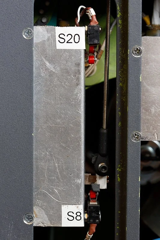
The actuator is partially visible; the blue coloured mechanism.  The parking brake vertical control rod, micro limit switch and upper part of the high tensile spring can be to seen to the lower right

What is an Actuator

An actuator is a type of motor that is responsible for moving or controlling a mechanism or system.  It is operated by a source of energy, typically electric current, hydraulic fluid pressure, or pneumatic pressure, and converts that energy into motion.

Almost every modern automobile has a door lock actuator which is responsible for the locking and unlocking of the door locks.  This website 'How Stuff Works' provides a very good overview of how an actuator works.

The actuator is responsible for maintaining the parking brake lever in the UP position.  This occurs when the circuit is closed and 12 volt power is briefly directed to the actuator to lock the device into the engaged position. 

The actuator used is an automotive door lock actuator - code BOLA-2 by Bullz-Audio (amazon link).

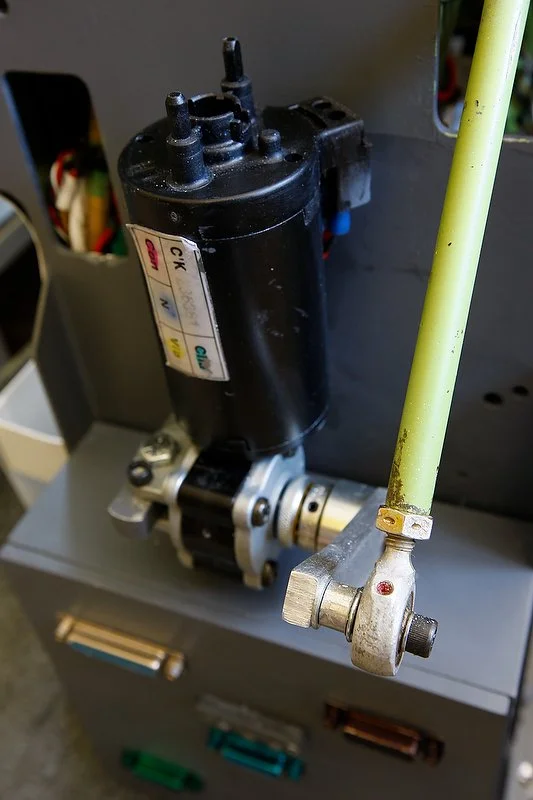
closer view of the mounted acctuator

System Overview

The actuator is the mechanism that enables the parking brake lever to be locked into the UP position.  Without power, the actuator is in the resting position and the parking brake lever is pulled to the DOWN position by a high tensile spring.

The annunciator is mounted horizontally on the Captain-side of the throttle quadrant and is powered by 12 volts.

To connect the actuator to the parking brake system, the following items have been used:

  • An actuator;

  • A micro-limit switch;

  • A relay;

  • A 12 volt power supply and busbar;

  • A standard interface card (Leo Bodnar BU0836A Joystick Controller card); and,

  • Depending upon your requirements (mechanical or part mechanical system), a Phidget 0/0/8 card (1017_1).

Registration of Parking Brake Movement

After the parking brake lever has been wired to the BU0836A card, the card must be registered in Windows.  After this has been completed the parking brake lever can be assigned in ProSim737 (configuration/MCP Throttle Switches), P3D, or via FSUPIC.

Relay and Micro-Switch

Two items are used to control whether power enters the circuit: a double throw relay and a micro-switch.

The relay is connected to the toe brakes, and when the brakes are depressed, the relay will close.  When the brakes are released the relay will open.  The connection of the relay to the toe brakes can be done a number of ways, but probably the easiest way is to install a button or micro-switch to the toe brakes.  A Phidget 0/0/8 card can also be used, but this method is slightly more convoluted.

The relay (open/closed) is triggered by the movement of the toe brakes.

A micro-switch is used to open or close the circuit when the parking brake lever is raised or lowered.

The micro-switch is mounted proximal to the vertical control rod, and when the parking brake is is in the DOWN position, the connectors from the micro switch are touching a flange that has been attached to the rod, however, when the parking brake lever is moved to the UP position, the connection is severed (circuit open or closed). 

The use of a micro-switch facilitates a second line of containment.  What this means is that the mechanism will only function fully when the relay is closed (toe brakes depressed) and the micro-switch is closed (parking lever raised).

The relay, either enables or inhibits 12 volt power to flow into the circuit, and this is dependent upon the whether the toe brakes are depressed.

The reason for this set-up will be understood shortly.

Toe Brakes

In the real aircraft, the parking brakes can only be engaged or disengaged when the Captain-side or First Officer-side toe brakes are depressed.  This mechanical system has been faithfully replicated by using a relay, micro-switch and actuator.

How It Works

The actuator will only engage when the toe brakes are depressed.  This means that the parking brake cannot be engaged (lever locked in the UP position with red annunciator on) or disengaged (lever in DOWN position with red annunciator off) unless the toe brakes are depressed. 

Depressing or releasing the toe brakes closes or opens the relay which in turn enables 12 volt power to reach the annunciator via the busbar.  However, the system is only 'live' (closed system) when the parking brake lever is moved to the UP position, enabling power to flow unhindered through the circuit.  When the toe brakes are released, the circuit is open and the actuator remains in the engaged locked position with the parking brake lever locked in the UP position.

To release the parking brake lever, the opposite occurs.  When the toe brakes are depressed, the relay opens directing power to the actuator which disengaged the actuator lock.  The parking brake lever is then pulled to the DOWN position by the tensile spring.

How To Engage The Parking Brake

The method used to engage the parking brake is as follows:

  1. Slightly depress the toe brakes.  This will open the relay and enable 12 volts to engage the actuator;

  2. Raise the parking brake lever to the UP position and hold it in this position; and,

  3. Release the toe brakes.  Releasing pressure on the toe brakes causes the actuator to lock into the engaged position, as the power ceases to flow to the actuator.

To release the parking brake, the toe brakes are depressed.  This will cause the actuator to unlock and return to its resting position.  The high tensile spring will pull the parking brake lever to the DOWN position with a loud snapping sound.

More Ways To Skin A Cat - Full Mechanical or Part-Mechanical

There are several methods that can be used to connect the actuator to the parking brake mechanism. No one method is better than the other.  I have outlined two methods.

(1)   Mechanical Method: This has been described above.

The toe brakes are connected to a relay (via micro-switches, buttons or whatever) and then connected with a busbar/12 volts power source, micro switch, and finally the actuator. 

Other than  connection of the parking brake lever to an interface card, and registration of the movement of the parking brake lever (either in ProSim-AR, FSX, or via FSUIPC) this method requires minimal software.

(2)  Part-mechanical/Software Controlled: This involves using the USER section in the configuration menu within ProSim-AR.

A Phidgets 0/0/8 relay card is connected to ProSim-AR and the the USER interface located in the configuration/switches menu of ProSim737 is programmed to read the movement for the toe brakes.  In this example USER 1 has been selected.  This process removes the need to install a micro-switch or button to the toe brakes.

Each USER IN has a corresponding USER OUT and this is located in GATES.  Opening Configuration/Gates, the same USER number is found (USER 1).  In the tab beside USER 1 the output from the Phidgets 0/8/8 card is entered.  Therefore, whenever USER 1 is triggered, there will be a corresponding output.

When the toe brakes are depressed, the software will read the movement and send a signal to the Phidget card to engage the relay.  This in turn will enable the busbar to be powered and the micro-switch to receive power.  Whether the parking brake lever is engaged (UP) or disengaged (DOWN) will open or close the micro-switch (closing or opening the circuit).  

The actuator will be engaged (circuit closed) only if the micro-switch (located on the vertical rod mentioned earlier) connection is severed (parking brake lever is in the raised position closing the circuit).

Actuator Power and Caution LED

The actuator, powered by 12 volts is connected to the 12 volt busbar in the Throttle Communication Module (TCM) and then, via a straight-through cable, to the Throttle Interface Module (TIM).  The relay for the parking brake mechanism is located in the TIM.

The design of an actuator is such, that if power is continuously applied to the mechanism, it will burn out.  If operating correctly, the actuator will onlt receive power when the toe brakes are depressed and the parking brake lever is raised at the same time.

To combat against the unforeseen event of power being continuously supplied to the actuator, for example by a relay that is stuck in the open (on) position, a coloured LED has been incorporated into the three LEDs that are fitted to the front of the Throttle Communication Module (TCM).  This flashing purple coloured LED illuminates only when the circuit is closed and the actuator is receiving 12 volt power.

Important Point:

  • Two terms often confused are open circuit and closed in relation to an electrical circuit.

Any circuit which is not complete is considered an open circuit.  Conversely, a circuit is considered to be a closed circuit when electricity flows from an energy source to the desired endpoint of the circuit.

Conversely, a closed relay means it allows voltage to travel through it, while an open relay is the opposite.

Additional Information

Like many things, there are several ways to accomplish the same or a similar task.  The following posts located in the ProSim737 forum discuss the conversion of the parking brake lever.

  • This article is one of several pertaining to the conversion of the OEM Throttle Quadrant

  • NOTE:  Since publication, ProSim-AR has incorporated into their software a parking brake release 'command'.  This by-passes the need to use the USER OUT settings mentioned above.  The command is set to the output on the Phidget 0/0/8 card.  The parking brake release can be found in the Configuration/Gates menu.  (MORE TO COME - in construction).

Throttle Quadrant Rebuild - Speedbrake Motor and Clutch Assembly Replacement

The motor that provides the power to move the speedbrake lever is attached via a slipper clutch to the speedbrake control rod. The slipper clutch can easily be adjusted and if set correctly provides the correct torque required for the speedbrake lever to move.   Below the motor is the Throttle Communication Module (TCM) that accommodates, amongst other things, the relays that are used by the logic to control the speedbrake lever's movemen

The mechanics of the speedbrake system has been completely overhauled, however, the logic that controls the speedbrake has remained ss it was. 

Several problems developed in the earlier conversion that could not be successfully rectified.  In particular, the speed of the speedbrake lever when deployed was either too fast, too slow, or did not move at all, and the clutch mechanism frequently became loose. 

Other minor issues related to the condition korrys that illuminate when the speedbrake is either armed or extended; these korrys did not always illuminate at the correct times.

The slipper clutch can easily be adjusted and if set correctly provides the correct torque required for the speedbrake lever to move.   Below the motor is the Throttle Communication Module (TCM) that accommodates, amongst other things, the relays that are used by the logic to control the speedbrake lever's movement.

Rather than continually‘tweak the earlier system, it was decided to replace the motor and clutch assembly with a more advanced and reliable system. To solve the arming issue, a linear throw potentiometer has been used to enable accurate calibration of the speedbrake lever in Prosim737.

Important Point:

  • To read about the first conversion and learn a little more about closed-loop systems and how the speedbrake works, please read the companion article PRIOR to reading this article.  This article only addresses the changes made to the system and builds on information discussed in the other article: 737 Throttle Quadrant  Speedbrake Conversion and Use

Motor and Clutch Assembly

A 12 volt motor is used to power the speed brake.  The motor is mounted forward of the throttle unit above the Throttle Communication Module (TCM).  The wiring from the motor is routed, in a lumen through the throttle firewall to a 12 volt busbar and relays.  The relays, mounted inside the TCM, are dedicated to the speedbrake. 

Attached to the 12 volt motor is a slipper-clutch assembly, similar in design to the slipper clutches used in the movement of the two throttle thrust levers.  The clutch can easily be loosed or tightened (using a pair of padded pliers) to provide the correct torque on the speedbrake lever, and once set will not become loose (unless exposed to constant vibration). 

diagram 1: slipper clutch cross section

The slipper clutch and bearings have been commercially made.

A linear throw potentiometer has been mounted on the Captain-sid of the quadrant.  The potentiometer enables the movement of the speedbrake lever to be finely calibrated in ProSim737

Speedbrake Mechanics

In the real Boeing 737 aircraft, buttons are located beneath the metal arc that the speedbrake travels.  If you listen carefully you can hear the buttons clicking as the lever moves over the button.  These on/off buttons activate as the speedbrake lever travels over them, triggering logic that causes the speedbrake to move.

This system has been replicated by using strategically placed micro-buttons beneath the speedbrake lever arc.  As the speedbrake lever moves over one of the buttons, the button will trigger a relay to either open or close (on/off).  The four relays, which are mounted in the Throttle Communication Module (TCM) trigger whether the speedbrake will be armed, stowed, engaged on landing, or placed in the UP position.

Speedbrake Korry (armed and extended)

The speedbrake system is a closed system, meaning it does not require any interaction with the avionics suite (ProSim737), however, the illumination of the condition lights (speedbrake armed and extended on the MIP) is not part of the closed loop system.  As such, the korrys must be configured in ProSim737 (switches/indicators). 

An easy workaround to include the arm korry to the closed loop system is to install a micro-switch under the speedbrake lever arc to correspond to the position of the lever when moved to the armed position.  Everytime the level over the micro-switch the arm korry will illuminate.

Speedbrake Operation

To connect the mechanical system to the avionics (ProSim737), a linear throw potentiometer has been connected to a Leo Bodnar BU0836A Joystick Controller card.  This enables the movement of the speedbrake lever to be calibrated in such a way that corresponds to the illumination of the korrys and the extension of the spoilers on the flight model.  The potentiometer has been mounted to the throttle superstructure on the Captain-side.

Using a potentiometer enables the DOWN and ARM positon to be precisely calibrated in ProSim737 (config/configuration/combined config/throttle/mcp/Levers).

The following conditions will cause the speedbrake lever to deploy from the DOWN to the UP position.

  1. When the aircraft lands and the squat switch is activated;

  2. During a Rejected Takeoff (RTO).  Assuming the autobrake selector switch has been set to RTO, there is active wheel spin, and the groundspeed exceeds 80 knots; and,

  3. If the reverse thrust is engaged with a positive wheel spin and a ground speed in excess of 100 knots.

Point (iii) is worth expanding upon.  The speedbrake system (in the real aircraft) has a built-in redundancy in that if the flight crew forget to arm the speedbrake system and make a landing, the system will automatically engage the spoilers when reverse thrust is engaged.  This redundant system was installed into the Next Generation airframe after several occurrences of pilots forgetting to arm the speedbrake prior to landing.  

Therefore, the speedbrake will deploy on landing either by activation of the squat switch (if the speedbrake was armed), or when reverse thrust is applied.

Speedbrake Logic ( programmed variables)

The following variables have been programmed into the logic that controls the operation of the speedbrake.

  1. Rejected Take Off (RTO).  This will occur after 80 knots call-out.  Spoilers will extend to the UP position  when reverse thrust is applied.  The speedbrake lever moves to UP position on throttle quadrant.  RTO must be armed prior to takeoff roll;

  2. Spoilers extend on landing when the squat switch is activated.  For this to occur, both throttle thrust levers must be at idle (at the stops).  The speedbrake lever also must be in the armed position prior to landing.  The speedbrake lever moves to UP position on throttle quadrant;

  3. Spoilers extend automatically and the speedbrake lever moves to the UP position when reverse thrust is applied;

  4. Spoilers close and the speedbrake lever moves to the DOWN position on throttle quadrant when the thrust levers are advanced after landing (auto-stow); and,

  5. Speedbrakes extend incrementally in the air dependent on lever position (flight detent).

The logic for the speedbrake is 'hardwired' into the Alpha Quadrant card.  The logic has not changed from what it was previously.

Speedbrake Lever Speed

When the speedbrake lever is engaged, the speed at which lever moves is quite fast.  The term ‘biscuit cutter’ best describes the energy that is generated when the lever is moving; it certainly will break a biscuit in two as well as a lead pencil.  Speaking of lead pencils, I have been told a favorite trick of pilots from yesteryear, was to rest a pencil on the throttle so that when the speedbrake engaged the pencil would be snapped in two by the lever!

The actuator that controls the movement of the speedbrake.  This image was taken from beneath the floor structure of a Boeing 600 aircraft.  Image copyright to Karl Penrose

In the real Boeing 737 aircraft the movement of the lever is marginally slower and is controlled by an electrically operated actuator (28 volts DC). 

In theory, the moderate speed that the speedbrake lever moves in the real aircraft should be able to be duplicated; for example, by suppressing the voltage from the 12 volt motor by the use of a capacitor, using a power supply lower than 12 volts, or by using speed controllers.  These alternatives have yet to be trailed.

It is unfortunate, that most throttle quadrants for sale do not include the actuator.  The actuator is not part of the throttle unit itself, but is located in the forward section under the flight deck.  The actuator is then connected to the speedbrake mechanism unit via a mechanical linkage.

In the real aircraft, the speedbrake lever and actuator provide the input via cables, that in-turn actuate the speedbrakes.  There is no feedback directly from the hydraulics and all operation is achieved via the manual or electric input of the speedbrake lever.

Actuator Sound

The sound of the actuator engaging can easily heard in the flight deck when the speedbrake engages (listen to the below video).  To replicate this sound, a recording of the actuator engaging was acquired.  The .wav sound file was then uploaded into the ProSim737 audio file library and configured to play when the speedbrake is commanded to move (squat switch).  

The .wav file can be shortened or lengthened to match the speed that the lever moves. 

Synopsis

I realize this and the companion article are probably confusing to understand.  In essence this is how the speedbrake operates:

  • A potentiometer enables accurate calibration (in ProSim737) of the DOWN and ARM position of the speedbreak lever.  This enables the condition korrys to illuminate at the correct time.

  • Micro-buttons have been installed below the arc that the speedbrake lever travels.  The position of each button, is in the same position as the on/off buttons used by Boeing  (the buttons are still present and you can hear them click as the speedbrake lever moves across a button).

  • The speedbrake system is a closed-loop system and does not require ProSim737 to operate.

  • The logic for the system has been programmed directly into the Alpha Quadrant card mounted in the Throttle Interface Module (TIM).  This logic triggers relays, located in the Throttle Communication Module (TCM) to turn either on or off as the speedbrake lever travels over the micro-buttons.  This is exactly how it's done in the real aircraft.

  • The micro-buttons are connected to a Phidget 0/0/8 relay card (4 relays).  The relay card is located within the Throttle Communication Module (TCM).

  • The speedbrake moves from the ARM position to the UP position when the squat switch is triggered (when the landing gear touches the runway).  The squat switch is a configured in ProSim737 (configuration/combined configuration/gate/squat switch).

Video

The upper video demonstrates the movement of the speedbrake lever.    The lower video, courtesy of U-Tube, shows the actual movement of the lever in a real Boeing aircraft.

The video is not intended for operational use, but has been shown to demonstrate the features of the speedbrake system.

If you listen carefully to both videos, you will note a difference in the noise that the actuator generates.  I have been informed that the 'whine' noise made by the actuator is slightly different depending upon the aircraft frame; the actuator in the older classic series Boeing being more of a high whine in comparison to the actuator in the Next Generation aircraft.


737-500 automated speedbrake deployment


Glossary

  • Condition(s) - A term referring to a specific parameter that is required to enable an action to occur.

  • FSUIPC - Flight Simulator Universal Inter-Process Communication.  A fancy term for software that interfaces between the flight simulator programme and other outside programmes.

  • Speedbrake Lever Arc - The curved arc that the speedbrake lever travels along.

  • Updated 11 July 2020.