Differential Reverse Thrust Using ProSim737
/
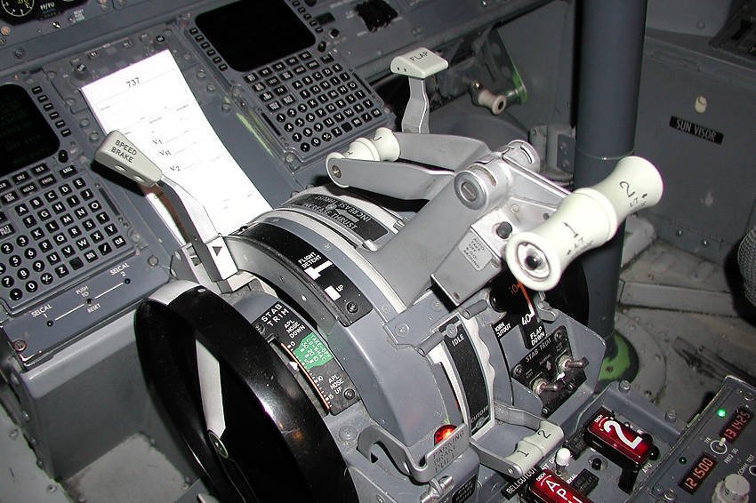
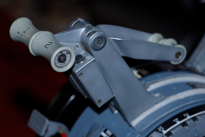
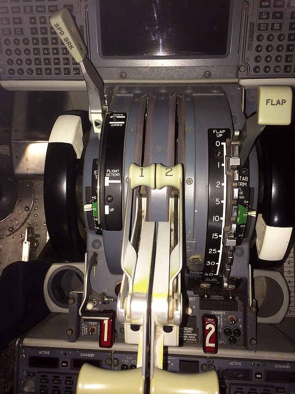
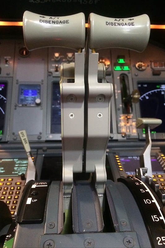
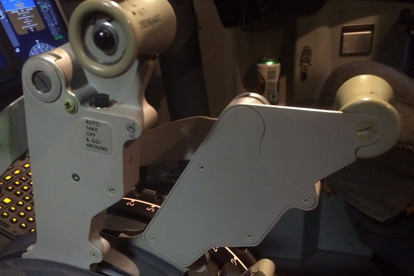
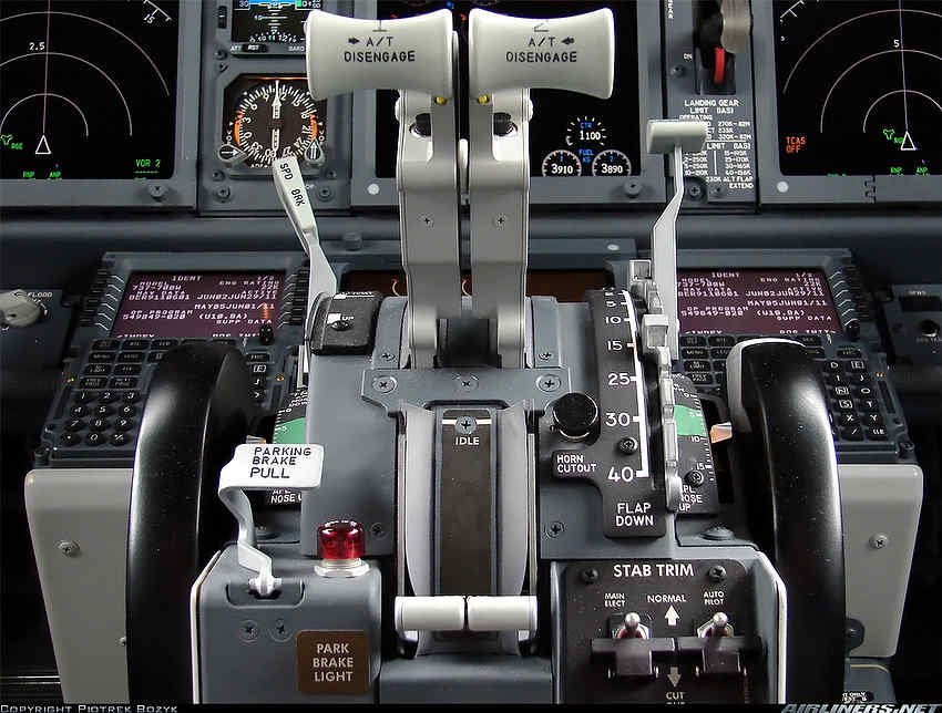
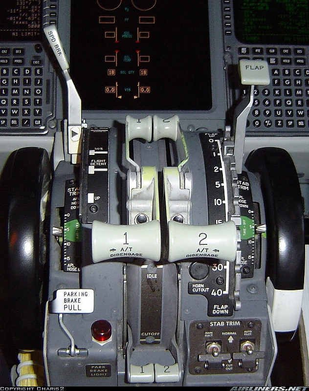
Reverse thrust levers
Being able to engage differential reverse thrust is very important. Not only for short field and cross wind landings, but also to minimise wear and tear, and heat buildup within the wheel braking system. The later being vital when engaging in quick turn around flights.
The Reverse Thrust System
The system is straightforward and uses two two dual Bourns string potentiometers and Leo Bodnar BU0836 Joystick card. The card is initially registered in Windows and then calibrated (once the potentiometer is connected) in ProSim737.
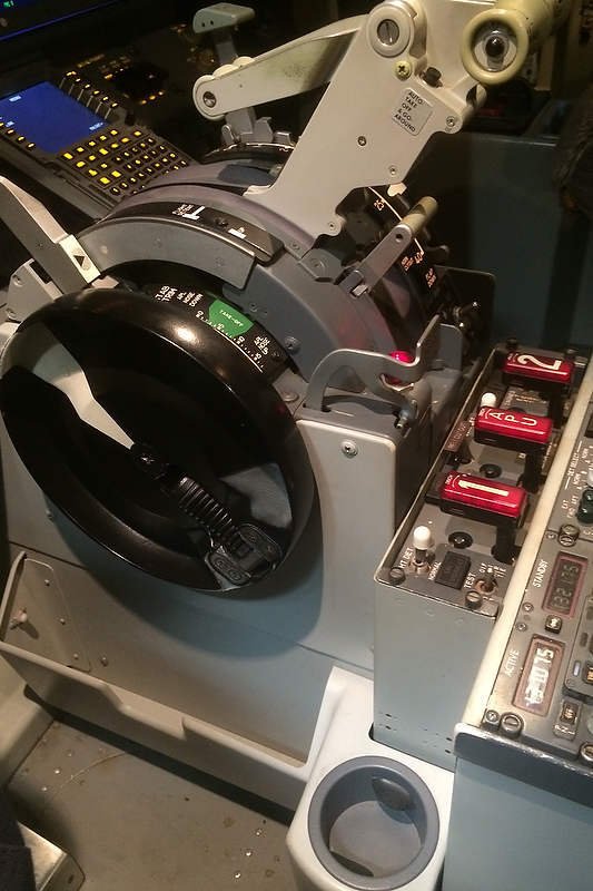
The dual potentiometer is mounted in the aft section of the throttle quadrant. Whilst it is not necessary to use a dual potentiometer, doing so reduces the amount of room required to mount separate potentiometers. Using a potentiometer enables the accurate calibration of each thrust lever and reverser lever, and more importantly, the reverse thrust is differential thrust. Using a potentiometer enables the full range of movement that the reverse thrust lever is capable of.
It is possible, in lei of using a string potentiometer, to use micro buttons preset to the position of the revere thrust levers, however, using buttons will only enable the reverse thrust to be either on or off, and it will not be possible to calibrate differential reverse thrust.
Potentiometers and Mounting
The main advantage of using a Bourns potentiometer is that they are designed and constructed to military specification, are very durable, and are sealed. The last point is important as sealed potentiometers will not, unlike a standard potentiometer, ingest dust and dirt. This translates to greater accuracy being maintained by the potentiometer and zero maintenance.
Traditionally, string potentiometers have been mounted either forward or rear of the throttle quadrant; the downside being that considerable room is needed for the operation and movement of the strings. Often, the string would rub infrastructure and wiring causing snagging issues and premature wear and tear to the string.
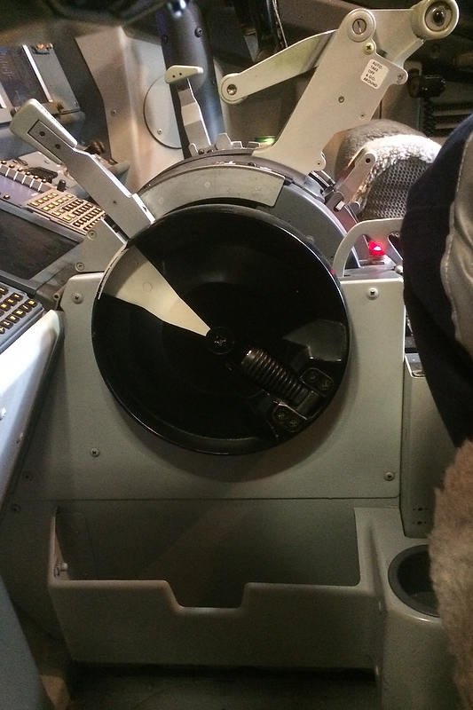
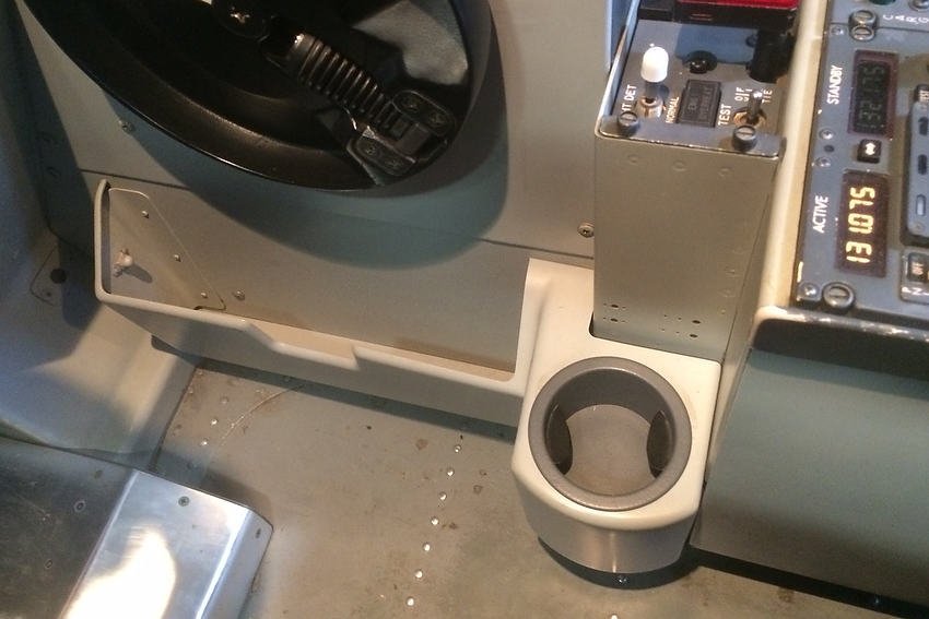
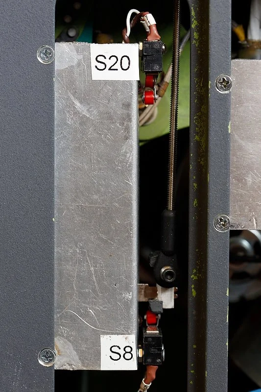
In this build, the potentiometers have been mounted on the rear wall of the throttle quadrant and the dual strings connected vertically, rather than horizontally. This has allowed maximum usage of the minimal space available inside the throttle quadrant. As described, two dual potentiometers have been used - one potentiometers caters toward the thrust lever and reverse thrust lever for throttle one, while the second potentiometer is dedicated to the throttle thrust lever and reverse thrust lever or throttle two.

Dual string potentiometer mounted to aft wall of throttle quadrant
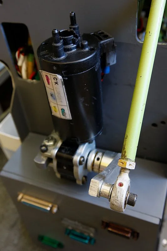
String Attachment
After the potentiometers have been securely mounted, the strings are attached vertically to the main throttle quadrant cog wheel. Attachment of the two strings can be by a number of methods. The most important aspect of the connection is that the string must always be under tension and must not snag on infrastructure, wiring or anything else - the strings must have clean movement. It is also important to take into account the string length, as each string needs to have enough length to calibrate the thrust lever and the reverse thrust lever. If the string is too short, there will not be enough string to enable calibration of the revere thrust lever. I recommend doubling the length of the string required for the thrust lever and adding approximately ten percent to the length.
Interface Card
The potentiometer requires an interface card to connect with the avionics suite and flight simulator. In this build, I have used a Leo Bodbar 0836A joystick card. The card is mounted in the Throttle Interface Module (TIM).
The reason a joystick card is used is that it enables each of the throttle thrust levers and reverser levers to be individually calibrated. As dual potentiometers are being used, each potentiometer will have two axis - one for the thrust lever and the other for the reverse thrust lever.
Registration and Calibration
Joystick Card Registration and Initial Calibration: To register the four axis’ of the joystick card, open the joystick interface module (type ‘JOY’ into the computer’s search bar to open the user interface). Once the registration interface is open, move each of the thrust levers forward and aft followed by the reverse thrust levers. Make sure you move the reverse thrust levers all the way from idle to maximum detente.
Calibration in ProSim737: To enable the full movement of the reverse lever to be registered, each of the reverse thrust levers must be calibrated, and the calibration saved in the avionics suite software (ProSim737). Calibration is done in the ProSim737 user interface (config/calibration/combined config/throttleMCP/lever/throttle reverser left and throttle reverser right).
With the user interface open to the correct throttle, select the appropriate axis from the drop down menu. To calibrate the reverse thrust lever, move the reverse lever from the closed position to the fully open position and select the positioning tabs in the software at closed, idle detente, and full detente positions.
As the calibration also includes the thrust levers, each of the thrust levers will also need to be calibrated. Repeat the instructions above (using the left and right throttle from the user interface), selecting the tab when the levers are at minimum (fully aft) and at maximum (fully forward). Save the calibration by pressing the OKAY tab.
Tweaking
Unfortunately, the calibration in some instances is rather arbitrary in that to obtain a correct setting, to ensure that both thrust levers are in the same position with identical %N1 outputs, the tab control must be tweaked left or right (followed by flight testing).
When tweaked correctly, the two thrust lever levers should, when the aircraft is hand-flown (manual flight), read an identical %N1 setting with both thrust levers positioned beside each other.
Reverse Thrust - Lever One and Two
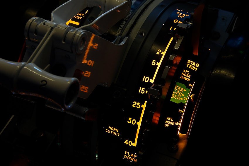
The video below demonstrates differential reverse thrust using theProSim737 avionics suite. The first segment displays equal reverse thrust while the second part of the video displays differential thrust.
Differential reverse thrust N1 displayed on EICAS (ProSim737) from dual potentiometer
Final Call
While reverse thrust can be easily configured using micro buttons, utilising two dual string potentiometers allows for precise and independent control of differential reverse thrust. This setup significantly enhances realism by enabling each reverse thrust lever to operate separately and accurately, just as in the real aircraft.
Additional Information