How to Wire and Use a Switch-mode Power Supply
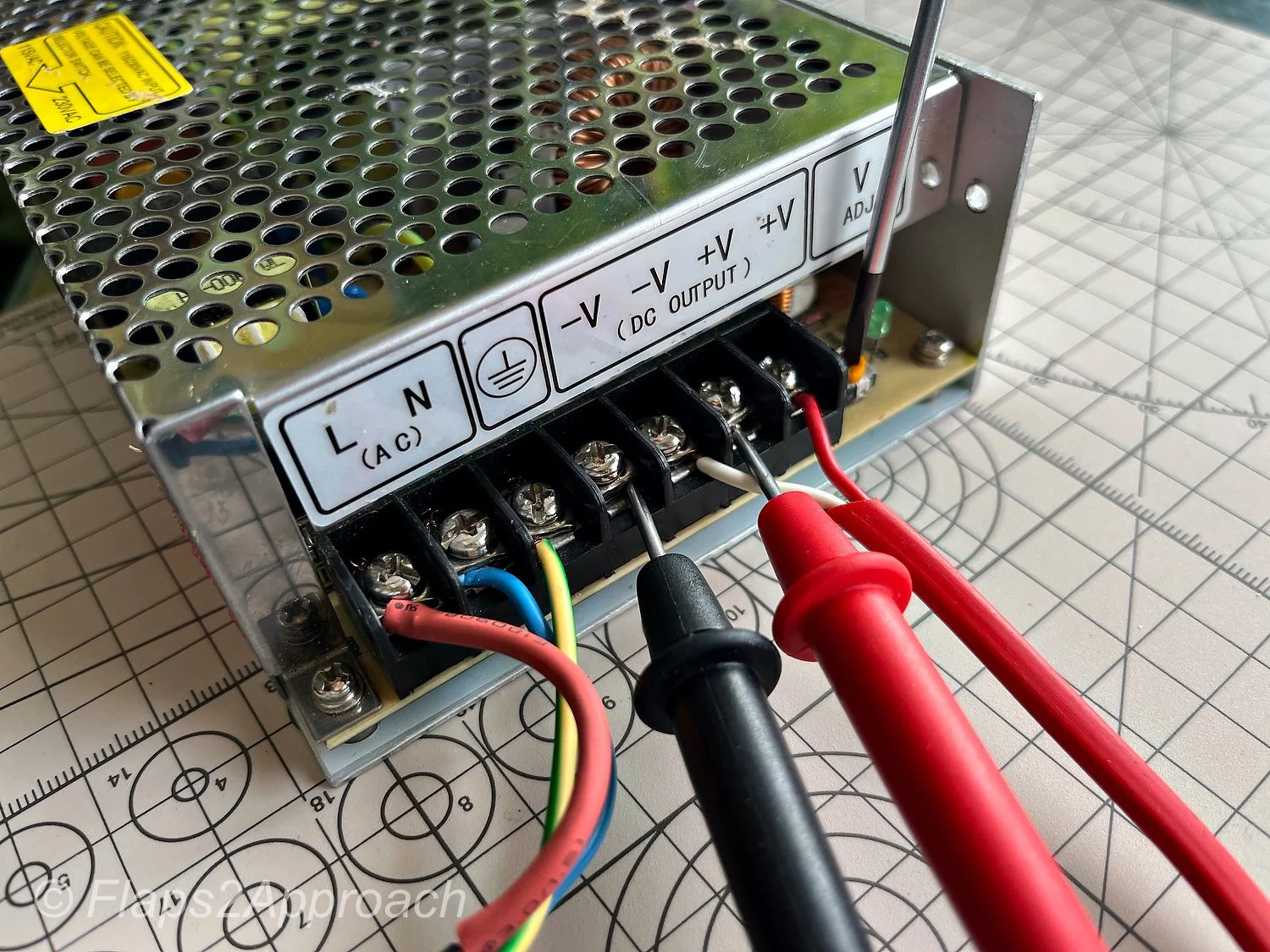
Red and black probes are connected to +V and -V to determine the correct voltage of the PSU

Power supply units (PSUs) are essential components in all but the most basic flight simulator setups. While simpler systems may use standard computer power supplies modified to deliver multiple voltage levels, these often lack sufficient amperage output. As a result, they are inadequate for more advanced configurations, which require power supplies that can be customised to meet specific system needs, provide multiple voltage outputs, and deliver higher amperage.

This need becomes particularly evident when using OEM components, which often require power sources capable of providing 5, 12, 24, and 28 volts, typically at high amperage.

In this article, I will address the use of switch-mode power supply units (SMPS) and explain how to connect several Mean Well power supplies (or similar models) to mains power using a single power cable.  Additionally, there is a discussion on how to protect power supplies and connected components from short circuits.

  • I use the term PSU (power supply unit) interchangeably with SMPS (switch-mode power supply).

Mean Well Switch-mode Power Supplies

Mean Well power supplies are a popular and reliable choice in various industries, including flight simulation.  Known for their high quality construction, durability, efficiency and versatility, Mean Well offers power supplies that can meet the demanding requirements of advanced flight simulators. These units are designed to deliver stable and efficient power across multiple voltages, making them suitable for complex setups that require precise voltage control and high amperage.

Establishing a Power Supply Unit System - A Systems Based Approach

In my simulator, I apply the concept of aircraft systems, assigning individual or grouped systems to dedicated power supplies. This system-oriented approach offers several benefits, most important being simplified troubleshooting; there is no need to trace which wires connect to which PSU - this makes troubleshooting simpler, faster and more intuitive.

Additionally, using a systems base approach ensures the power supplies are not running at their maximum amperage, as each system rarely requires the full amperage of the power supply.  Typically, I aim to operate a power supply at no greater than 80% of its full load capacity.  This results in a longer lifespan for the PSU, less heat generation, and the ability for the power supply to provide more amperage if and when additional components are connected.

A major advantage in using Mean Well switch-mode power supplies is that they have been designed to provide a constant source of clean power rated at 20% above the certification provided.  Therefore, if you run the power supply at 100% it has a further 20% before the unit will automatically turn off to avoid being damaged.

The downside of this dedicated approach is that you probably will need additional power supplies that wouldn’t be necessary with a more generic setup.  While the benefits of tailored power management are clear, the added complexity and cost of additional units can be a trade-off.  There is no definitive right or wrong way.

Parallel or Series

A PSU can be connected to another PSU either in series or in parallel.  While each method has its pros and cons, unless there is a specific need for parallel connection, I recommend connecting them in series (also known as daisy chaining), as it is by far the easier option.

The primary reason for connecting PSUs in series is to enable multiple units to operate using a single power cord connected to the mains supply. This process will be explained in more detail later in the article.

Connecting PSUs in parallel, on the other hand, is used when additional amperage is needed at the same voltage, but the amperage cannot be generated solely by one PSU.  To connect power supplies in parallel, they must have identical voltage and amperage ratings and ideally be identical units.  For example, two 28 volt, 6-amp power supplies can be connected in parallel to produce 28 volts at 12 amps.

Safety

It's crucial to emphasise the importance of safety when working with any power supply. Regardless of voltage or current levels, electricity demands respect. Proper precautions and safety protocols must always be followed.

Important Points:

  • Be vigilant to what you are doing at all times.

  • Turn off mains power (and remove the plug) at the mains whenever working with a power supply unit (do not work on ‘live’ equipment).

  • Always cover or secure any AC terminals to avoid accidental contact.

  • Never leave any system in its ‘live’ state (for instance, if leaving the room).

  • No matter how skilled you are, it is very easy to accidentally touch a live terminal or wire when working in a confined space.

  • Note that after using a power supply, there will be resident power in the unit after it has been disconnected from mains power.  Allow this power to dissipate before touching any terminals.  Mean Well power supplies have a LED light that slowly decreases in illumination as the power drains from the unit.

Voltage and Amperage – What Power Supply Do I Need

Power supplies have differing voltage and amperage. 

Voltage is the output of a power supply.  For example, 5 volts output is required to illuminate the backlighting on an OEM panel and 28 volts is required to illuminate OEM Korrys, while 12 volts may be required to power a small 12 volt motor.

  • Volts represent the potential difference between two points, or the pressure driving the current.  To relate it to a more tangible concept, it's like water pressure in a pipe.

  • Amperage (Amps), on the other hand, measures the current flow or how many electrons are flowing through a conductor per second.  In other words, Amps is a measurement of how strong the water is that travels through the pipe.

For example, illuminating the backlighting on an OEM panel with five bulbs requires a 5 volt power supply that provides sufficient amperage to illuminate the bulbs. However, if you have twenty panels, each with five bulbs, you'll still need a 5 volt power supply, but it must deliver significantly higher amperage to illuminate all the bulbs simultaneously at the correct intensity.

Determining the required amperage for a particular panel should not be guesswork; it can be a time consuming process to measure the current draw for each component.

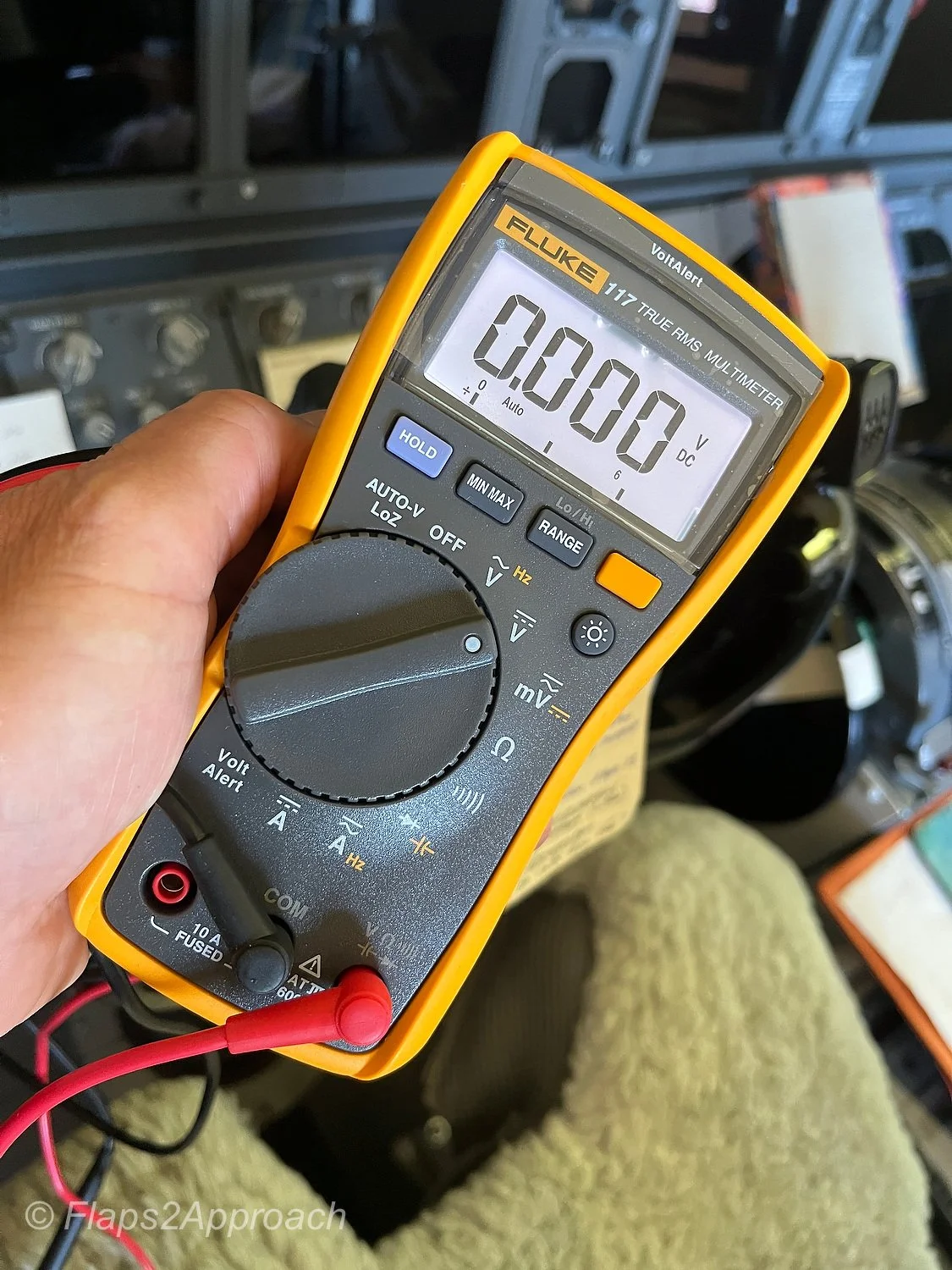
fluke multimeter is a high-end brand, however, for basic electronics such as determining amperage draw, a fluke is probably overkill

Measuring Amperage

By far the easiest way to measure amperage is to use a portable multimeter. 

First, the multimeter is set to measure current (amperage). Next, the red probe is removed from the black COM jack and inserted into the red AMP jack.

Second, the connection between the power source and the component to be measured is broken and the two probes from the multimeter connected inline.

When the PSU is turned on, the current that is used by the component will be displayed on the screen of the multimeter.

Important Point:

  • If you are connecting the multimeter's probe directly to the PSU, it is recommended to use a small alligator clip and a separate piece of wire.  This will minimise damage to the tip of the probe.  Connect the wire to the terminal on the PSU and the probe to the alligator clip.

The video ( bottom of page beneath photo gallery) demonstrates how to use a multimeter.  Amperage measurement is towards the end of the video.

Wiring a Power Supply Unit

There are several different types of switch-mode power supplies on the market.  Generally speaking, all will have at one end of the unit a collection of terminals.  Each terminal will be protected from the adjacent terminal by a vertical barrier (usually made from solid plastic).  Some units may also have a plastic cover that folds down and clips into place to protect the terminals.

The terminals (from left to right) are as follows:

  • L (AC) – Line in (positive) - LIVE;

  • N (AC) – Neutral (common) - usually zero volts or close to;

  • Earth – 3 horizontal lines and 1 vertical line (or similar);

  • DC Output – +V and -V; and,

  • V ADJ – Voltage adjustment.

It’s important to realize that there are a variety of symbols (called iconography conventions) that are used to represent Earth; most have a circle as part of the design (although Mean Well do not use a circle).

rear of psu showing nomenclature and colour coding for wires

In short, AC is mains power (115 Volts or 240 Volts).  DC is output voltage (5, 12, 28 Volts, etc)

L is the terminal that you must be wary of.  NEVER touch this terminal unless the PSU is disconnected from the mains power; this terminal has mains power connected and is LIVE and ACTIVE.

Following the connection of the wires, I make it a point to not touch anything on the AC side (L or N). Furthermore, these terminals should always be protected by a cover or piece of insulation tape (see below).

+V and -V are the terminals used to connect your components.  For example, you may want to power a panel’s backlighting.  The positive wire from the component is connected to the terminal marked +V and the negative wire is connected to the terminal marked -V.  The output of these terminals is at whatever voltage the power supply is rated at.

Terminal Busbar

You will notice that most power supplies have only four output terminals. While it’s feasible to piggyback wires from multiple components that use identical voltage onto these terminals, I wouldn’t recommend doing so. Instead, I suggest connecting a terminal busbar to the +V and -V terminals. The wires from each component can then be connected directly to the busbar. This approach allows you to connect multiple components without the need for piggybacking directly to the terminals on the PSU.

The advantages of using a busbar are as follows;

  • One busbar can be dedicated to a specific aircraft system;

  • Enables additional components to be added to the busbar (depending on busbar size);

  • Minimizes the need to touch the PSU as the busbar is where components are connected; and,

  • If wanted, the busbars can be segregated neatly in an area that is easier to reach for maintenance;

Protective Covers

After connecting any wires to the terminals, either close the plastic protective cover (if supplied), cover the terminals with red or yellow coloured tape (if temporary), or if the connection is to be semi-permanent, apply a dab of silicon sealant to the terminal.   This will provide an additional layer of protection (from accidentally touching the terminals). Although covering the terminals on the DC side is not required, it's highly recommended. When working on the simulator, it's surprisingly easy to drop a screw, washer, or other small item onto exposed terminals. If +V and –V are accidentally bridged, it will cause a short circuit, potentially damaging components.

Another good working option is to use a hot glue on all live terminals.  The hot glue will seal around the terminal creating an effective barrier to electrical current.  To remove the hot glue, use 100% alcohol which will cause the glue to loose its adhesive ability.

unless you have a spare set of probes, it’s best to attach a wire to the terminal and then connect the probe to the wire with an alligator clip. This will minimise potential damage to the probes

Voltage Adjustment (V-ADJ)

Located on the far right of the PSU is a screw labeled V-ADJ, short for voltage adjustment. This feature is standard on all switch-mode power supplies and allows the output voltage to be fine-tuned slightly above or below the unit’s nominal rating. For instance, a 28 Volt PSU can typically be adjusted to deliver between 24 and 32 Volts. The V-ADJ screw provides precise control, enabling you to tailor the output voltage to meet the specific requirements of your application.

It is safe to use a small Philips head screwdriver on the V-ADJ screw, but be very careful to not touch any of the terminals.  If you are concerned that this may occur, apply shrink tubing to the shaft of the screwdriver.  The tubing will act as an insulator shield.

To measure the voltage adjustment, connect the two probes of a multimeter to the +V and -V terminals on the power supply. Ensure the multimeter is set to DC voltage (Volts DC).  Once the power supply is turned on, the multimeter will display the output voltage being generated. You can then adjust the voltage by turning the V-ADJ screw clockwise or counter clockwise, depending on whether you want to increase or decrease the voltage.

The video ( bottom of page beneath photo gallery) demonstrates how to use the voltage adjustment screw.

Important Point:

  • To avoid damage to the probes of the multimeter, connect a short wire from the terminal of the PSU and connect the probe to the end of this wire with an alligator clip.

How to reduce the Number of Power Cables

Depending on your setup, you may be using six or more power supplies. To reduce the number of required power cables and corresponding mains outlets, each PSU can be connected in series, also known as daisy-chaining, to share a single power source. This approach streamlines cable management and simplifies the overall electrical layout.

To do this, connect a wire from each of the three AC terminals on one power supply to the corresponding terminals on the next power supply: L to L, N to N, and earth to earth.  This can be done for any number of power supply units.

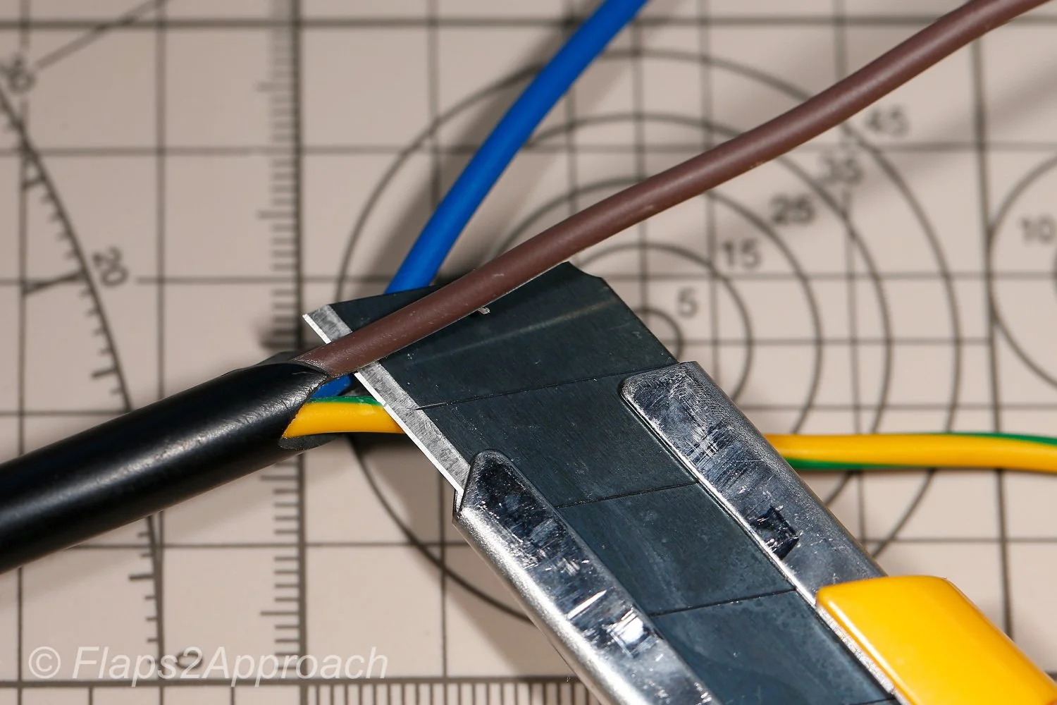
If you're unsure what size wire to use, I recommend repurposing a disused electrical power cable (most of the wires bundled in these cables is 14 gauge wire (AWG) rated at 15 Amps).  Carefully slice open the outer PVC insulation, taking care not to damage the internal wires, and use one or more of these wires.  In general, 14-16 gauge wires (AWG) is recommended.

However, make sure the wire is made from 100% copper, not aluminium-coated copper. To verify this, use a blunt knife to gently scratch the wire. If it sheds silvery or aluminium-like fragments, discard it and use a wire that shows solid copper throughout.

The reason for this is that copper is a very good conductor of electricity, whereby, aluminium, brass, and other composite metals is not.

Terminal Connectors and Colour

While terminal connectors can enhance the professional appearance of the project, they may introduce reliability issues if not properly crimped or connected, potentially resulting in poor contact. To minimise intermittent faults, the bare end of the wire should be attached directly to the terminal and secured beneath the flat clamping plate using the screw.

Whenever bare wires are used, their ends should be ‘flow soldered’. This will eliminate any loose wire strands and make the connection more reliable.  Additionally, apply appropriately coloured heat shrink tubing to the end of each wire. This not only helps with wire identification but also minimises the amount of bare metal exposed at the terminal, improving both safety and neatness.

Many countries follow different color coding standards for electrical wiring.  In general:

  • Red is positive;

  • Black is negative (which is the same as common in simple DC systems); and,

  • Brown is earth (ground).

If a different colour is used outside the norm, use red, black or brown heat shrink to colour code the end of the wire that is secured to the terminal on the PSU. Colour consistency is important to avoid future confusion. If an unusual colour combination is used, ensure that the colours and voltages are documented, and a label is adhered to the side of the power supply or other visible area.

If you look carefully at the photographs, you will notice that I have used three colours on the AC side; Red for AC L, Blue for N, and yellow for earth. +V and -V use red and white wires respectively. In my simulator, I use this colour standard for all wires attached to the AC side of the PSU. Other wires may use different colours depending upon the aircraft system and the wire’s use.

Circuit Protection (Discussion)

Back-flow current, also known as reverse conventional current (in some circles), refers to the flow of electrical current back to the source via the negative (common) wire in a circuit. This can happen when a circuit is accidentally short-circuited.

Short circuits can occur for a variety of reasons.  For example, accidentally bridging two terminals on an interface card with a screwdriver, dropping a metallic object (such as screw) onto exposed terminals causing an arc, or a wire coming loose and making contact with the incorrect polarity.

When a short circuit occurs, the current can flow back to the switch-mode power supply through the negative wire. This often results in damage to the power supply and may also affect any other interface cards or components connected to the same ground path.

Many enthusiasts in an attempt to minimise such a problem occurring, use an inline fuse installed to the earth (ground) wire.  Typically the fuse, which is rated at approximately 15% less the amperage of the power supply, is connected as close as possible to the PSU.  The theory is that the fuse will protect the circuit and any components connected to that circuit should a short circuit occur. 

However, blade and glass cartridge pencil fuses are designed to break only when an electrical surge flows through them at a high amperage, such as when a short circuit occurs across a 12 volt vehicle battery (12 volt automotive batteries usually have a very high amperage).  The amperage, in this case, that reaches the fuse is very high and breaks the fuse's metal connection bridge. 

In a simulator environment, if a problem occurs, the amperage flowing back to the PSU is probably not going to be high enough to break the metal bridge in the fuse.  The fuse will become warm, but not be warm enough to cause the fuse to break.  Whilst this may not damage components outright, it may cause incremental damage.

If additional protection is required, inline automotive fuses are probably not beneficial.  Circuit breakers, which are more sensitive to low amperage electrical surges, can be used. 

However, at some point the cost and complexity outweighs the advantages.  Rather than provide protection that is not absolutely necessary, it is a better practice to enforce strict guidelines when dealing with circuits:

  • Ensure that all terminals are protected by a cover, hot glue, or in case of busbars a protective cover.  A cover if need be can be made from modelling plastic;

  • Use heat shrink on all wires; thereby,  minimising the exposure of metal; and,

  • Only work on wiring, interface cards, etc when the power is turned off at the mains.

Mean Well Power Supplies

I contacted Mean Well directly, and they confirmed that their power supplies are equipped with internal protection against short circuits. In the event of a short circuit, the unit will shut down to prevent damage (see short circuit protection in next section). However, if high voltage is fed back into the power supply, beyond its designed protection capacity, the internal safeguards will probably be compromised, resulting in permanent damage to the power supply.

Short Circuit Protection (SCP):

Most Mean Well power supplies include SCP as a standard feature. When a short circuit occurs at the output, the PSU usually enters a hiccup mode (repeatedly attempts to restart) or it latches off (requiring a manual restart).  Which type of protection is triggered will depend on the model of the power supply.  Either way, the use of SCP will help prevent damage to both the PSU and downstream components should a short circuit occur.

It's also worth noting that Mean Well PSU's are internally protected against electrical surges (from the mains).  

Documentation and Labelling

Many enthusiasts overlook the importance of documenting and labeling components, assuming they'll remember everything. However, memory fades over time - especially in simulator projects with extensive wiring. Without clear labels and records, troubleshooting or upgrading later can become a frustrating and time-consuming task.

Power supply units must be labelled clearly with their voltage and amperage for easy identification. Similarly, all wires should be correctly tagged with their voltage and function.

If it’s not possible to record the function on the actual wire, consider implementing a labelling code. For example, an output wire from a PSU could be labelled 28V/A1, 28V/A2, and so forth, where A1 and A2 identify the wire's function. A small cheat sheet can be made and kept nearby for reference.

There are many labelling options available, ranging from inexpensive plastic tie tags to professional labelling systems that use labelled heat shrink.  However, keep in mind that solid plastic tags (or flags), while cost-effective, can cause issues during maintenance. These tags will often snag when wires are accessed and are pulled through - often causing more hassle than what they are worth.

I use an assortment of label types (heat shrink, flexible laminate and flags) to label all wires, power supplies, and related components.  I use a Brother E-560 BTVP labelling machine.

Mounting and Securing Power Supplies

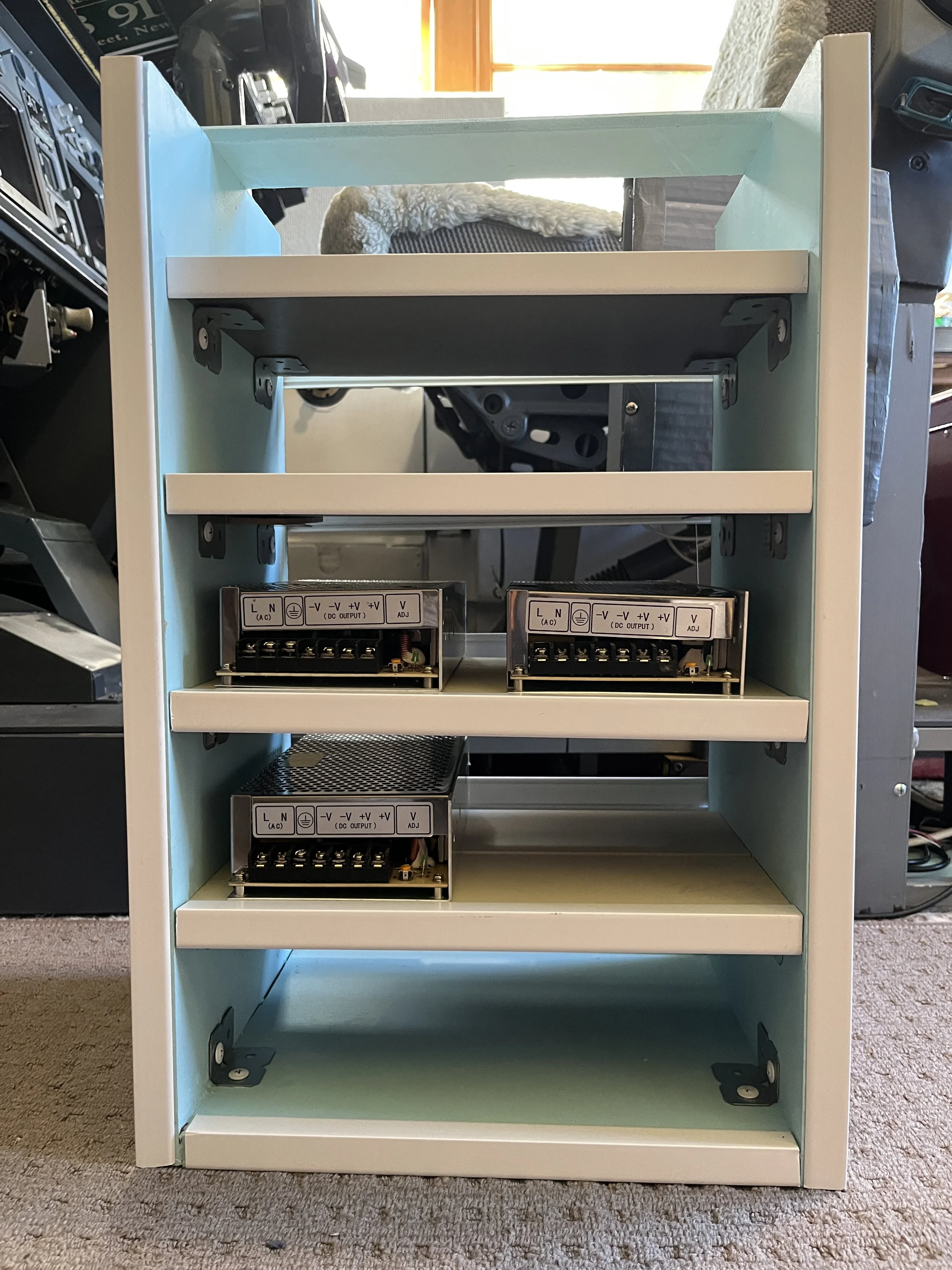
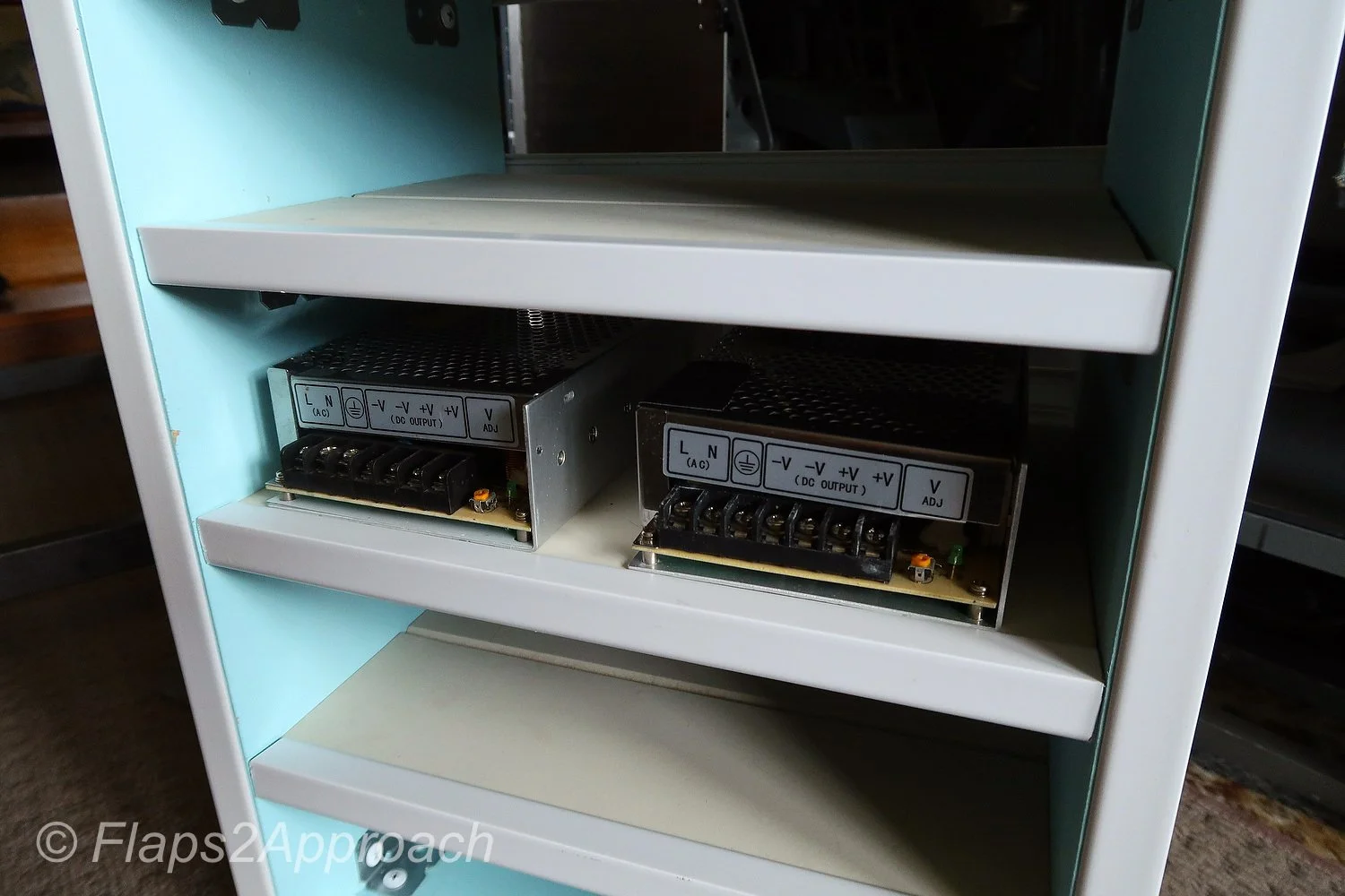
Power supplies can be mounted more or less anywhere, but preference should be given to keeping all the supplies close together in a location that is readily accessible.  Furthermore, the power supplies should be attached to something solid and must not be placed loosely under the platform.   If so inclined, Mean Well markets a rail that enables each PSU to be attached. 

In my setup. I have fabricated a wooden cabinet with several shelves; each shelf can accommodate two switch-mode power supplies.  The cabinet is open at both ends enabling cross-flow ventilation to minimise heat build-up.  If you install the power supplies in a confined area then it is wise to also install a cooling fan.   

Maintenance

Power supplies, for the most part, do not require maintenance.  However, dust build-up can be an issue if operating in a dusty environment.  This is especially evident if the power supply being used has an external fan; over time the fan can cause dust ingress. 

If thick dust accumulates on a power supply, it can cause the unit to operate at elevated temperatures, potentially shortening its lifespan. Accumulated dust can also burn easily when the power supply heats up causing an unwanted burning odour.

It is an easy matter to remove the casing from the power supply, and using a small vacuum, remove any accumulated dust.  Before doing this, turn off the mains power and remove the cable from the mains outlet.  Furthermore, ensure there is no residual power in the power supply; capacitors can hold power for a considerable period. 

Important Point:

  • Avoid touching a power supply unit or any components connected to it immediately after shutdown. Enable any residual charge to dissipate.

Mean Well Power Supplies

Some of the advantages of using Mean Well power supplies are summarised below:

  • Constant source of clean power rated at 20% above the certification provided;

  • Protection from short circuit, overload and over voltage;

  • Fixed switching at 25 kHz (produces a cleaner and better regulated power);

  • Two or three year replacement warranty (model dependent);

  • Internal cooling fan (model dependent);

  • Fan operation is temperature controlled;

  • Audible alarm that sounds if operating temperature is exceeded (model dependent);

  • Adjustable voltage (the voltage can be manually adjusted up or down (-+) to ensure correct voltage);

  • Wide range of operating conditions (-25 Celsius to 70 Celsius);

  • Solid enclosure with perforated holes (efficient heat sink and cooling); and,

  • Easy screw attachment point or ability to use a rail system.

Mean Well power supplies are manufactured in Taiwan (ROC) - not to be confused with China.

In this article, I have focused on Mean Well power supplies, however, there are several other brands available.  For the most part these 'other' brands function identically to Mean Well, however, some do not have the quality assurance (QA) and features that Mean Well is renown for.

Final Call

Wiring and connecting power supplies is generally a straightforward process, as is connecting components to the positive and negative terminals. However, the most critical aspect of this task is electrical safety. Proper documentation and clear labeling must take precedence over speed or convenience. Rushing through the process without thorough documentation can result in significant confusion during future troubleshooting and fault-finding, particularly in complex systems where accurate traceability is important.

Additional Information

Gallery


Tutorial that demonstrates various features of a multimeter (courtesy U-Tube)


How to adjust voltage output on switch-mode power supply. Note that the probes are attached directly to the terminals. I have two sets of probes and use one set for this type of thing. i recommend using alligator clips and a short set of wire if you do not have a spare set of probes


Why The Aircraft Should Be in a Clean Configuration Before Engaging the Autopilot

ryanair takeoff

I was recently using a friend’s simulator and suggested that he fly the first leg. He decided to not select LNAV and VNAV before takeoff; he wanted to manage vertical and lateral roll himself, however, did select the autothrottle.  He was keen to begin (fly), and although he was using the FMC, he did not set the correct takeoff trim for the aircraft's weight.  Instead, he guessed the takeoff trim (based on previous flights). 

I was surprised when my friend engaged the autopilot and Level Change very soon after takeoff, with flaps 5 and the landing gear extended, and then was more surprised when he raised the flaps at the incorrect speeds.  The combination of a number of factors: incorrect takeoff trim, an almost immediate selection of the autopilot and Level Change, failing to retract the landing gear, and not adhering to the correct flap manoeuvring speed resulted in excessive attitude during the initial takeoff and climb.  This in turn resulted in a slow airspeed, a low altitude call out, and an increase in thrust followed by the vibration of the stick shaker. 

In this article, I will explain why engaging the autopilot before the aircraft is in a clean configuration is generally not recommended. I will also outline three key reference indicators that help determine the appropriate timing for flap retraction, and I will highlight the differences in flap retraction proceedures during a VNAV and Level Change takeoff during a standard flaps 5 takeoff.  Finally, I will offer practical recommendations to support a smooth and seamless transition from manual flying to automated flight.

Autopilot Use after Takeoff

Pilots very rarely use the autopilot during the initial climb out, preferring to hand fly the aircraft to flaps UP, and in some cases transition altitude, before engaging the autopilot.  This said, if a Standard Instrument Departure (SID) is complicated and requires several turns, then a pilot may select the autopilot at an earlier time, but typically this will not be before flaps UP, and if it is, the aircraft will be in correct trim prior to engaging the autopilot.

The autopilot is not engaged immediately after takeoff primarily because the aircraft, with flaps and landing gear extended, is not in a clean configuration and is still travelling at a relatively slow airspeed (takeoff thrust).  Engaging the autopilot too early may result in unpredictable behaviour, for example, attitude or speed anomalies, as my friend experienced.  More critically, if the autopilot were to fail at such a low altitude, there may be insufficient time or altitude to recover the aircraft safely..

Furthermore, engaging the autopilot before the flaps are fully retracted will cancel any speed bugs on the Primary Flight Display (PFD) that are tied to flap retraction.  This means that the flight crew will need to manually manage the airspeed at which the flaps are retracted; thereby increasing workload.

Attitude and Speed Settings - What Happens

When the autopilot is engaged, it primarily controls the aircraft based on attitude. Attitude refers to the aircraft’s orientation relative to the horizon, including pitch (nose up or down) and bank (left or right). The autopilot system uses sensors and flight control computers to maintain the desired attitude, ensuring a smooth and stable flight. This is done in conjunction with the Autothrottle.

If the autopilot is engaged with the flaps and landing gear extended, the autopilot may alter the aircraft's attitude to maintain the desired speed (V2+15/20 KIAS during takeoff); this is a dynamic response.   When the flaps are extended they increase lift and drag, causing the aircraft to pitch up and lose speed. The autothrottle will then increase thrust to maintain airspeed.  If not managed correctly, flaps and landing gear extension and retraction can cause a cycle of increasing and decreasing speed.

Trim Settings

Takeoff trim settings are important.  If the takeoff trim is incorrect for the aircraft’s weight, the corresponding V speeds provided by the FMC will not be correct.  An incorrectly trimmed aircraft can result in, amongst other things:

  1. An excessive use of the runway length during the takeoff roll;

  2. Over excessive control column angles;

  3. Incorrect airspeed; and,

  4. Excessive attitude.

All of the above, when combined, can lead to a snowball of problems, and even more so if the autopilot is engaged at a low altitude prior to the flaps and landing gear being retracted.  This is what my friend sourly experienced.

Important Points:

  • The transition from hand flying to automated flight will be straightforward and relatively seamless if the aircraft is in trim, the aircraft has adequate airspeed, and the flaps and landing gear are retracted. 

  • Whenever hand flying the aircraft, the trim should be set so that there is minimal back pressure required on the yoke (Do not trim the aircraft during rotation).

Retraction of Flaps (Visual Aids)

Flap retraction on the Boeing 737 often begins at V2+15/20 KIAS.  V2 represents the takeoff safety speed, while adding 15 to 20 KIAS provides a safe margin above stall speed as the aircraft accelerates during the climb.

Retraction should not occur before the aircraft has reached V2+15/+20 KIAS.  Typically, this is when the aircraft reaches Acceleration Height.  This stated, the minimum altitude that flaps can be retracted is 400 feet AGL.   If the aircraft’s airspeed is below V2+15/20 KIAS, flap retraction should not occur and the bank angle should be limited to 15 degrees.  If the aircraft’s airspeed is at or above V2+15/20 KIAS, and the speed is increasing, the first flap retraction can occur.

There are three visual aids, located on speed tape on the Primary Flight Display (PFD), that can be used to help determine the correct time to retract the flaps:

  • The Flap Manoeuvring Speed bug;

  • The Speed Trend Vector arrow; and,

  • The V2+15 KIAS white carrot bug.

Flap Manoeuvring Speed Bug

The Flap Manoeuvring Speed bug is a green-coloured line. The bug indicates when to retract the current flaps detente.  For example, when the aircraft's airspeed matches or passes through the flaps 5 designation you would select flaps 5 to flaps 1.  Then, when the airspeed passes through the flaps 1 position you would select flaps 1 to flaps UP.

Another way to think of the flap manoeuvring speed is it is the minimum airspeed that the flaps can be retracted.

Speed Trend Vector Arrow (STV)

Located on the speed tape on the PFD is a vertical arrow called a Speed Trend Vector (STV).  The Speed Trend Vector will display a green-coloured upwards, neutral or downwards facing arrow. 

During climb-out, the Speed Trend Vector arrowhead can be used to determine how long it will take for the aircraft, at the current thrust setting and wind conditions, to reach the speed that the arrowhead is pointing at (usually around 10 seconds).  Therefore, when the upward arrowhead reaches the flap manoeuvring speed bug, the aircraft will pass through this flaps détente in approximately 10 seconds.

The Speed Trend Vector also aids in determining if the speed of the aircraft is increasing, is stable, or is decreasing. This is important, as initial flap retraction should only occur when the speed of the aircraft is increasing. If the STV displays a stable or negative facing arrow, the initial retraction of flaps should be delayed.

Importantly, the Speed Trend Vector is 'live', meaning that the computer takes into account the aircraft's airspeed, vertical speed, and wind direction prior to displaying the vector on the PFD.  The Speed Trend Vector is also a useful tool during descent and on approach, when managing airspeed is critical.

White Carrot Indicator Bug

Located on the speed tape on the PFD is a white-coloured marker called a carrot (the carrot looks more like a sideways facing arrow).  The position of the carrot indicates V2+15 or V2+20 KIAS (the + speed is determined by the engine type and can be set to +15 or +20 in the ProSim IOS).

The carrot is a visual aid to indicate when the aircraft's airspeed has reached V2+15 KIAS.  This is the minimum speed at which the flaps can start to be retracted. 

The carrot is automatically removed from the display after the first flap retraction has occurred.

Flap Retraction - VNAV and Level Change Takeoff (V2+15)

VNAV Takeoff

  • At 400 ft AGL, VNAV becomes active.

  • At Acceleration Height (1000–1500 ft AGL), VNAV commands a pitch reduction to accelerate.

  • Flap retraction begins at V2+15 and continues as each flap manoeuvre speed is reached.

  • The autopilot can be engaged after 400 ft AGL for smoother transitions.

Level Change (LVL CHG) Takeoff

  • Used when VNAV is not armed or not preferred.

  • At Acceleration Height, the pilot selects flaps up speed in the MCP and engages LVL CHG.

  • Aircraft pitches to maintain that speed, allowing flap retraction as each flap manoeuvring speed is reached.

  • Autopilot is selected when flaps are fully retracted (discretion of pilot in command).

The key consideration is that a Level Change takeoff requires more manual monitoring of airspeed and pitch, in contrast to a VNAV takeoff which is smoother for flap retraction.

Flap Retraction Example (V2+15)

During a standard flaps 5 takeoff the following flaps retraction schedule should be followed:

When the airspeed reaches V2+15 or above or matches the Flap Manoeuvring Speed bug, and the Speed Trend Vector shows a positive arrow display, the first flaps retraction can occur (flaps 5 to flaps 1). When the airspeed matches the position of flaps 1, the flaps can be retracted to the UP position.

IMPORTANT POINT:

  • Be aware that the flaps do not retract instantly; depending upon the flap detente, the time it takes for the flaps to retract can be a few seconds. This should be taken into consideration, especially during a higher flap takeoff such as a flaps 25 takeoff.

Recommendations (Transition From Hand Flying To Automated Flight)

The transition from hand flying the aircraft to automated flight should be as seamless as possible.  To reduce the likelihood of unwanted or unexpected deviations from the desired flight path (for example, excessive attitude and/or an increase or decrease in thrust):

  1. The takeoff trim should be correct for the aircraft’s weight;

  2. The aircraft must have adequate airspeed;

  3. The flaps should be retracted as per the flap manoeuvring speed;

  4. The autopilot should not be engaged below 400 feet AGL;

  5. The autopilot should not be engaged before flap retraction is complete (1), and,

  6. The autopilot should be engaged only when the aircraft is in trim (neutral stick).

If these recommendations are followed, the transition from manual to automated flight will be barely discernible.

(1)  Technically speaking, the 737-800 can have the autopilot engaged before flaps retraction, however, best practice is to engage the autopilot after the flaps have been retracted.  Many operators stress that the flaps must be retracted prior to engaging the autopilot.  This said, ultimately it is at the discretion of the pilot in command.

Important Points:

  • The minimum altitude for initial flap retraction is 400 feet AGL, but most flight crews will begin to retract flaps at V2+15/20 KIAS or when the aircraft reaches Acceleration Height.

  • Flap retraction should be initiated upon reaching the manoeuvring speed for the current flap setting with the aircraft's airspeed increasing, unless the airspeed is above V2+15/20 KIAS and increasing; whereby, the first flap retraction can occur.

  • The white carrot is a handy reference to V2+15/+20 KIAS.

Autothrottle Disconnect Before Autopilot Disconnect

I also want to mention one further caveat when transitioning from automated to manual flight, and this involves the disconnection of the autopilot and autothrottle - not so much during a takeoff but at other stages during the flight.

Whenever hand flying the aircraft, the autopilot and autothrottle must not be engaged, but which do you disengage first - autopilot or autothrottle. Best practice is to always disconnect the autothrottle before the autopilot. The reason being is that the aircraft ‘s autothrottle system will respond more quickly than the autopilot (the last thing you need is for the autothrottle to spool after disconnecting the autopilot). Furthermore, do not disconnect both in rapid fire - take your time and wait a second between disconnecting the autothrottle followed by the autopilot. This enables a more seamless transition to occur.

Additional Information:

Final Call

My friend had an intense few minutes as the automated system attempted to fly the parameters that had been entered into the FMC and establish flight conditions based on the aircraft's configuration - a task made more difficult by the fact that the stick shaker was active and the altitude was below 600 feet.

Although this occurred in a simulator, it underscores an important lesson: preparation is key to a successful flight. There must be a clear plan for when specific actions will take place, and shortcuts must be avoided. Had my friend set the correct takeoff trim based on the aircraft's weight and refrained from engaging the autopilot while the aircraft was still in an unclean configuration at a low airspeed, the stick shaker probably would not have been triggered, and the flight could have been recovered. Unfortunately, with such low altitude, there was no margin for error - and the result was a simulator reset.

Video

The video shows the various displays discussed. The take off was a VNAV takeoff and the autopilot was engaged immediately after the flaps were fully retracted.


Primary Flight Display showing various takeoff guides discussed in main article


Flap retraction (courtesy U-Tube). This is not from flaps-2-approach


Image Gallery

Acronyms

AGL - Above Ground Level

Attitude - The orientation of the aircraft relative to the horizon, typically described in terms of pitch (nose up/down), roll (bank left/right), and yaw (nose left/right).

KIAS - knots indicated airspeed. 

Differential Reverse Thrust Using ProSim737

Reverse thrust levers

Being able to engage differential reverse thrust is very important. Not only for short field and cross wind landings, but also to minimise wear and tear, and heat buildup within the wheel braking system. The later being vital when engaging in quick turn around flights.

The Reverse Thrust System

The system is straightforward and uses two two dual Bourns string potentiometers and Leo Bodnar BU0836 Joystick card. The card is initially registered in Windows and then calibrated (once the potentiometer is connected) in ProSim737.

The dual potentiometer is mounted in the aft section of the throttle quadrant. Whilst it is not necessary to use a dual potentiometer, doing so reduces the amount of room required to mount separate potentiometers. Using a potentiometer enables the accurate calibration of each thrust lever and reverser lever, and more importantly, the reverse thrust is differential thrust. Using a potentiometer enables the full range of movement that the reverse thrust lever is capable of.

It is possible, in lei of using a string potentiometer, to use micro buttons preset to the position of the revere thrust levers, however, using buttons will only enable the reverse thrust to be either on or off, and it will not be possible to calibrate differential reverse thrust.

Potentiometers and Mounting

The main advantage of using a Bourns potentiometer is that they are designed and constructed to military specification, are very durable, and are sealed.  The last point is important as sealed potentiometers will not, unlike a standard potentiometer, ingest dust and dirt.  This translates to greater accuracy being maintained by the potentiometer and zero maintenance.

Traditionally, string potentiometers have been mounted either forward or rear of the throttle quadrant; the downside being that considerable room is needed for the operation and movement of the strings. Often, the string would rub infrastructure and wiring causing snagging issues and premature wear and tear to the string.  

In this build, the potentiometers have been mounted on the rear wall of the throttle quadrant and the dual strings connected vertically, rather than horizontally.  This has allowed maximum usage of the minimal space available inside the throttle quadrant. As described, two dual potentiometers have been used - one potentiometers caters toward the thrust lever and reverse thrust lever for throttle one, while the second potentiometer is dedicated to the throttle thrust lever and reverse thrust lever or throttle two.

Dual string potentiometer mounted to aft wall of throttle quadrant

String Attachment

After the potentiometers have been securely mounted, the strings are attached vertically to the main throttle quadrant cog wheel. Attachment of the two strings can be by a number of methods. The most important aspect of the connection is that the string must always be under tension and must not snag on infrastructure, wiring or anything else - the strings must have clean movement. It is also important to take into account the string length, as each string needs to have enough length to calibrate the thrust lever and the reverse thrust lever. If the string is too short, there will not be enough string to enable calibration of the revere thrust lever. I recommend doubling the length of the string required for the thrust lever and adding approximately ten percent to the length.

Interface Card

The potentiometer requires an interface card to connect with the avionics suite and flight simulator. In this build, I have used a Leo Bodbar 0836A joystick card. The card is mounted in the Throttle Interface Module (TIM).

The reason a joystick card is used is that it enables each of the throttle thrust levers and reverser levers to be individually calibrated. As dual potentiometers are being used, each potentiometer will have two axis - one for the thrust lever and the other for the reverse thrust lever.

Registration and Calibration

Joystick Card Registration and Initial Calibration: To register the four axis’ of the joystick card, open the joystick interface module (type ‘JOY’ into the computer’s search bar to open the user interface). Once the registration interface is open, move each of the thrust levers forward and aft followed by the reverse thrust levers. Make sure you move the reverse thrust levers all the way from idle to maximum detente.

Calibration in ProSim737: To enable the full movement of the reverse lever to be registered, each of the reverse thrust levers must be calibrated, and the calibration saved in the avionics suite software (ProSim737). Calibration is done in the ProSim737 user interface (config/calibration/combined config/throttleMCP/lever/throttle reverser left and throttle reverser right).

With the user interface open to the correct throttle, select the appropriate axis from the drop down menu. To calibrate the reverse thrust lever, move the reverse lever from the closed position to the fully open position and select the positioning tabs in the software at closed, idle detente, and full detente positions.

As the calibration also includes the thrust levers, each of the thrust levers will also need to be calibrated. Repeat the instructions above (using the left and right throttle from the user interface), selecting the tab when the levers are at minimum (fully aft) and at maximum (fully forward). Save the calibration by pressing the OKAY tab.

Tweaking

Unfortunately, the calibration in some instances is rather arbitrary in that to obtain a correct setting, to ensure that both thrust levers are in the same position with identical %N1 outputs, the tab control must be tweaked left or right (followed by flight testing).

When tweaked correctly, the two thrust lever levers should, when the aircraft is hand-flown (manual flight), read an identical %N1 setting with both thrust levers positioned beside each other. 

Reverse Thrust - Lever One and Two

The video below demonstrates differential reverse thrust using theProSim737 avionics suite. The first segment displays equal reverse thrust while the second part of the video displays differential thrust.


Differential reverse thrust N1 displayed on EICAS (ProSim737) from dual potentiometer


Final Call

While reverse thrust can be easily configured using micro buttons, utilising two dual string potentiometers allows for precise and independent control of differential reverse thrust. This setup significantly enhances realism by enabling each reverse thrust lever to operate separately and accurately, just as in the real aircraft.

Additional Information

737 Derates and the Boeing Quiet Climb System

A derate occurs when the engine's power is reduced to less than its full capacity.

Derates are not complicated; however, when they are discussed together, the subject matter can quickly become convoluted; mainly because the names for the differing derates are similar. I have attempted to try and keep things as simple as possible.

For those interested in simulating real world proceedures, an understanding of derates is essential.

This topic was previously part of a broader article. To improve readability and update the content, it has been separated from the original.

In this article, we will explore the following:

  • Derated Takeoff Thrust (fixed derate);

  • Assumed Temperature Method (ATM);

  • Derated Climb Thrust (CLB-1 & CLB-2); and,

  • The Quiet Climb System (often called cutback).

Reduced Thrust Derates (General Information)

Derates are not complicated; however, when they are discussed together, the subject matter can quickly become confusing; mainly because the names for the differing derates are similar. I have attempted to try and keep things as simple as possible.

Engine derates on a Boeing 737 refer to the intentional reduction in engine thrust during certain flight conditions to optimise engine performance, and increase the longevity of the engines. A derate involves limiting the maximum available thrust that an engine can produce under specific conditions.

Typically, the takeoff performance available from an aircraft is in excess of that required, even when accounting for an engine failure. As a result, airline management encourage flight crews to use a derate, when possible.

Purpose of Engine Derates:

  1. Safety and Engine Longevity: Derating can help prevent engine stress and prolong the life of the engine, especially during takeoff and climb phases.

  2. Performance Optimisation: It can help maintain more efficient fuel burn, manage high temperatures, and reduce engine wear.

  3. Environmental Conditions: In cases of high ambient temperature or high altitude airports, derating helps reduce the engine's demand on performance.

Derates can be assessed on the N1 Limit Page in the CDU. The following derates, applied singly or in combination, are possible:

  • Derated Takeoff Thrust (fixed derate).

  • Assumed Temperature Method (ATM) ; and,

  • Derated Climb Thrust (CLB-1 & CLB-2).

When To Use a Derate

Possible reasons for using or not using a derate are:

  • Environmental considerations (runway condition, weather, wind, etc);

  • Ambient temperature;

  • Airport’s height above sea level;

  • The weight of the aircraft’s load including fuel;

  • Consideration to airline management;

  • The length of the runway; and,

  • Noise abatement.

Electronic Flight Bag (EFB) or Takeoff Performance Tables

A derate is not selected idly by the flight crew. Most airlines use an Electronic Flight Bag (EFB) or another approved source to calculate a suitable derate. If an EFB is unavailable, the aircraft performance data tables in the Flight Crew Operating Manual (FCOM) must be consulted, and the calculations done manually.

Using a derate is not always an option in all situations. For example, in high-performance scenarios, such as heavy takeoffs, high density altitudes, or congested airspace, full thrust may be required. Similarly, a derate may not be suitable if the weather is extremely hot, or if the aircraft is heavy and the runway is short. The final decision on whether to use a derate rests with the Captain of the aircraft.

Thrust Mode Annunciations and Displays

When a derate is used, the thrust mode annunciation (the annunciation is displayed in green-coloured capitals) will be displayed in the Upper Display Unit on the EICAS. The display will differ depending on the airline option.

Possible displays are as follows:

  • TO – takeoff (displayed if no derate is used) - option without derate.

  • TO 1 – derated takeoff 1 - option without double derate.

  • TO 2 – derated takeoff 2 - option without double derate.

  • D-TO – assumed temperature reduced thrust takeoff (ATM) - option with double derate.

  • D-TO 1 – derate one and assumed temperature reduced thrust takeoff (ATM) - option with double derate.

  • D-TO 2 – derate two and assumed temperature reduced thrust takeoff (ATM) - option with double derate.

  • CLB-1 – climb derate.

  • CLB-2 – climb derate.

We will now examine the derates available in the Boeing 737 aircraft.

1 - Derated Takeoff Thrust (Fixed Derate)

A fixed derate is a certified takeoff rating lower than a full rated takeoff thrust. In order to use a fixed derate, takeoff performance data for a specified fixed derate is required (Boeing FCTM 2023). This information is available either from the EFB or from the aircraft performance data tables in the FCOM.

The N1 Limit page in the CDU displays three fixed-rate engine derates: 26000, 24000 and 22000 (26K, 24K and 22K). Selection of a derate will command the software to limit the maximum thrust of the engines to whatever has been selected; nothing is altered on the actual engine. Selecting a derated engine thrust can only occur when the aircraft is on the ground.

Once a fixed derate is selected, it will remain in force until the aircraft reaches acceleration height or a pitch mode is engaged, at which point the fixed derate will be removed.

The N1 for the selected derate is displayed on the NI Limit page, the TAKEOFF REF page (LSK-2L) and in the N1 RPM indication in the Upper Display Unit (%N1 RPM readout and N1 reference bug) on the EICAS.

Thrust Limitation (Fixed Derate)

When using a fixed derate, the takeoff thrust setting is considered a takeoff operating limit. This is because the minimum control speeds (Vmcg and Vmca) and stabiliser trim settings are based on the derated takeoff thrust.

The thrust levers should not be advanced beyond the N1 RPM indication unless takeoff conditions require additional thrust on both engines (e.g., during windshear). If the thrust levers are advanced beyond the N1 RPM indication—such as in the event of an engine failure during takeoff—any increase in thrust could lead to a loss of directional control.

Important Point:

  • A fixed derate can be used on a runway that is either wet, has standing water, or has slush, ice or snow ( provided the performance data supports use of such a derate).

2 - Assumed Temperature Method (ATM)

The assumed temperature method is not exactly a derate; however, it has been discussed because the use of ATM can reduce takeoff thrust.

This method calculates thrust based on a assumed higher than actual air temperature and requires the crew to input into the CDU a higher than actual outside temperature.  This will cause the on-board computer to believe that the temperature is warmer than what it actually is; thereby, reducing N1 thrust. This reduces the need for full thrust, achieving a quieter and more fuel-efficient takeoff.

Using ATM, the desired thrust can be be incrementally adjusted by changing the temperature to a higher or lower value. This can be an advantage to a flight crew as they can fine tune the thrust setting to exactly what is required, rather than using a fixed derate.

ATM is effective only above a certain standard temperature. The 737 Next Generation engines are flat-rated to a specific temperature. In the case of the CFM-56, this is ISA +15°C or 30°C on a standard day. This means the engine can provide full thrust up to that temperature. However, if the temperature exceeds this limit, the engine will produce less thrust. When ATM is used, the temperature must always be set higher than the engine’s flat-rated temperature. Otherwise, the engine will continue to provide full thrust.

Once ATM is selected, it will remain in force until the aircraft reaches acceleration height or a pitch mode is engaged, at which point ATM will be removed.

The desired thrust level is obtained through entry of a SEL TEMP value on the N1 Limit Page (LSK-1L) or from the Takeoff Ref Page 2/2 (LSK-4L).

To delete an assumed temperate the delete key in the CDU should be used.

Thrust Limitation (ATM)

An ATM is not the same as a true derate, even though the takeoff thrust is reduced. This is because when using ATM, the takeoff thrust setting is not considered a takeoff operating limit, since minimum control speeds (Vmcg and Vmca) are based on a full rated takeoff thrust.

At any time during takeoff using ATM, the thrust levers may be advanced to the full rated takeoff thrust (Boeing, 2023 FCTM; 3.17).

Important Points:

  • ATM may be used for takeoff on a wet runway, provided the takeoff performance data (for a wet runway) is used. However, ATM is not permitted for takeoff on a runway contaminated with standing water, slush, snow, or ice.

  • During an ATM takeoff, the yoke may require additional back pressure during rotation and climb.

  • If another derate is selected in combination with ATM, the calculation for takeoff thrust is accumulative. Selecting more than one derate can affect the power that is available for takeoff and significantly increase roll out distance for takeoff.

ATM Annunciations and Displays

When ATM is used, the temperature used to calculate the required thrust and the calculated N1 will be displayed:

  • In the Thrust Mode Display in the Upper Display Unit on the EICAS (e.g., R-TO +35); and

  • On the N1 Limit page and the TAKEOFF REF page (LSK-1L & LSK-1R) in the CDU.

3. Combined Derate (Fixed Derate & ATM)

A fixed derate can be further reduced by combining it with the ATM. However, the combined derate must not exceed a 25% reduction from the takeoff thrust.

Thrust Limitation (Fixed Derate & ATM Combined)

When conducting a combined fixed derate and ATM takeoff, takeoff speeds consider Vmcg and Vmca only at the fixed derate thrust level.

The thrust levers should not be advanced beyond the fixed derate limit unless conditions during takeoff require additional thrust on both engines, such as in the case of windshear (Boeing, 2023 FCTM; 3.18).

If the assumed temperature method is applied to a fixed derate, additional thrust should not exceed the fixed derate N1 limit. Otherwise, there may be a loss of directional control while on the ground.

4 - Climb Derate (Derated Climb Thrust - CLB-1 & CLB-2) 

There are two climb mode derate annunciations: CLB-1 and CLB-2. CLB refers to normal climb thrust. To enter a climb derate, the N1 Limit page is opened in the CDU. The possible annunciations are as follows:

  • CLB: Normal climb thrust (no derate);

  • CLB-1: Approximately a 10% derate of climb thrust (climb limit reduced by approximately 3% N1; and,

  • CLB-2: Approximately a 20% derate of climb thrust (climb limit reduced by approximately 6% N1).

The use of a climb derate commands the autothrottle to reduce N1 to the setting calculated by the computer for either CLB-1 or CLB-2. The climb derate begins when the aircraft reaches the thrust reduction height (TRH) or during any climb phase up to FL150.

A climb derate can be selected either on the ground or while the aircraft is airborne; however, if during the climb, the vertical speed falls to below 500 feet per minute, the flight crew should manually select the next higher climb rating (for example, change from CLB-2 to CLB-1). As the aircraft climbs, the climb thrust is gradually reduced until full thrust is restored.

It is a common misconception that using a climb derate will minimise the volume of fuel used; however, this is incorrect.

The use of climb thrust does not save fuel; in fact, it consumes more fuel than full-rated takeoff thrust. However, using a lower climb thrust extends engine life and minimises maintenance. Ultimately, the extended engine life and reduced maintenance costs outweigh the additional fuel expense.

To remove a climb derate, either select CLB on the N1 Limit page or use the delete key on the CDU. The latter method is preferred because it deletes the selected climb derate rather than simply unselecting it.

Climb Derate Annunciations and Displays

When a climb derate is used, the derate selected and the corresponding N1 will be displayed:

  1. In the Thrust Mode Display on the Upper Display Unit on the EICAS (the annunciation is displayed in green-coloured capitals);

  2. On the NI Limit page and on the TAKEOFF REF page (LSK-2L) in the CDU;

  3. On the N1 RPM indicator; and,

  4. By the N1 reference bug.

After takeoff, the climb derate will also be displayed on the Climb page in the CDU.

The possible annunciations that can be displayed in the the thrust mode display are:

  1. TO (takeoff without a derate); and,

  2. R-TO (reduced takeoff thrust CLB-1 or CLB-2).

After takeoff, and when the thrust reduction height has been reached, the display will change to whatever climb derate was selected (CLB, CLB-1 or CLB-2).

Important Caveat (all derates):

It is important to note in relation to any derate that the FMC will automatically calculate a corresponding climb speed that is less than or equal to the takeoff thrust. Therefore, a flight crew should ensure that the climb thrust does not exceed the takeoff thrust.

This may occur if a derate or combination thereof is selected, and after takeoff, the flight crew select CLB. Selecting CLB will apply full climb thrust; however, this does not account for any adjustments made by the computer to the initially selected derate. As a result, the climb thrust may be greater than the takeoff thrust.

Boeing Quiet Climb System (QCS) - Abiding with Noise Abatement Protocols

The Boeing Quiet Climb System (often called cutback and referred to by line pilots as ‘hush mode’), is an automated avionics feature for quiet procedures that causes thrust cutback after takeoff.  By reducing and restoring thrust automatically, the system lessens crew workload and results in a consistently less noisy engine footprint, which helps airlines comply with noise abatement restrictions. There are two variables to enter: Altitude reduction and altitude restoration.

During the takeoff checklist procedure, the pilot selects the QCS and enters the height AGL at which thrust should be reduced.  This height should not be less than the thrust reduction height. The thrust restored height is typically 3000 feet AGL, however, the height selected may alter depending on obstacle clearance and the noise abatement required. 

With the autothrottle system engaged, the QCS reduces engine thrust when the cutback height is reached to maintain the optimal climb angle and airspeed. When the airplane reaches the chosen thrust restoration height (typically 3,000 ft AGL or as indicated by noise abatement procedures), the QCS restores full climb thrust.  Note that the minimum height that the QCS can be set is 800 feet AGL. 

The two heights referenced by the Quiet Climb System can be modified in the CDU (TAKEOFF REF 2/2 page (LSK-5R)). The system can be selected or unselected at LSK-6L (on/off).

Important Point:

  • The QCS is not designed to be used with multiple derates (derate + ATM); however, it can be used in conjunction with one or the other. This said, the minimum thrust cutback (thrust reduction height ~800 feet AGL) represents the minimum level of thrust that would ensure a sufficient climb gradient if an engine were to fail. The minimum thrust cutback ensures an engine-inoperative climb gradient of 1.2 percent. If one engine fails after cutback, the thrust from the operating engine must maintain a climb gradient of at least 1.2 percent.

Multiple Safety Features for Disconnect

The Quiet Climb System (QCS) incorporates multiple safety features and will continue to operate even in the event of system failures. If a failure occurs, the QCS can be exited by either:

  1. Selecting the takeoff/go-around (TOGA) switches on the throttle control levers, or

  2. Disconnecting the autothrottle and controlling thrust manually.

ProSim737

The Quiet Climb System was previously a component of the ProSim737 avionics suite; however, it was removed with the release of version 3.33. It is now available only in the professional version of ProSim737, not in the domestic version.

As a result, if a takeoff requires noise abatement, the necessary calculations and settings must be performed manually. This process is not difficult, as a fixed derate, ATM, or a combination thereof, along with the acceleration height, can be entered or adjusted based on the requirements of either an NADP 1 or NADP 2 procedure.

Figure 2: For completeness, and to provide an example of the altitude above ground level (AGL) that a noise abatement procedure uses.

Figure 2: Noise Abatement Departure Procedures (NADP). (click image for larger view).

Similarity of Terms

When you look at the intricacies of the above mentioned derates there is a degree of similarity.

The way I remember them is as follows:

Derated Takeoff Thrust is when the N1 of the engines is reduced (26K, 24K or 22K). This is done prior to takeoff;

Assumed Temperature Method (ATM) is when the N1 is lowered by changing the ambient temperature to a higher value in the CDU. This is done prior to takeoff;

Climb Derate (Derated Climb Thrust - CLB-1 & CLB-2) is when the N1 used during the climb phase is set to a lower power setting. Selecting a climb derate can be done either prior to takeoff or when the aircraft is airborne; and,

The Quiet Climb System enables a minimum and maximum height to be set in the CDU; thereby, reducing engine power and engine noise.  The restoration height is the height AGL that full climb power is restored.  The QCS is used only for noise abatement.

Final Call

Acceleration height, thrust reduction height, and derates are critical elements in optimising the takeoff performance of the Boeing 737.

Acceleration height is the altitude at which the aircraft’s nose is lowered to gain speed and the flaps are retracted, while the thrust reduction height determines at what height above ground level (AGL) to reduce engine power, from takeoff thrust to a lower setting. By adjusting the engine thrust settings and applying derates, operators can enhance engine longevity, improve fuel efficiency, and reduce noise during takeoff.

Understanding and properly applying these settings not only ensures compliance with performance regulations, but also contributes to operational efficiency. Ultimately, these parameters enable operators to maximise safety, minimise fuel consumption, and optimise aircraft performance during takeoff.

Acronyms Used

  • AGL – Above Ground Level

  • CDU – Control Display Unit

  • CLB-1 & CLB-2 – Climb 1 and Climb 2

  • DERATE – Derated Thrust

  • FL – Flight Level

  • FMC – Flight Management Computer

  • LSK-1R – Line Select 1 Right (CDU)

  • PFD - Primary Flight Display

  • QCS – Quiet Climb System

  • TMD – Thrust Mode Display

  • Vmca – Defined as the minimum speed, whilst in the air, that directional control can be maintained with one engine inoperative.

  • Vmcg – Defined as the minimum airspeed, during the takeoff at which, if an engine failure occurs, it is possible to maintain directional control using only aerodynamic controls. Vmcg must not be greater than V1.

Gallery: Various screen grabs from the CDU showing the effect on %N1 for various fixed derates and Assumed temperate (ATM). 

Acceleration Height and Thrust Reduction Height

Thompson B738NG transitioning to Thrust Reduction Height, Immediately following this will be acceleration height when the aircraft’s nose is lowered, flaps are retracted and climb thrust commences, acceleration will be reached, Manchester, UK (Craig Sunter from Manchester, UK, Boeing 737-800 (Thomson Airways) (5895152176), CC BY 2.0)

The takeoff phase of a flight is one of the busiest and most critical periods, and during this time, several distinct functions occur in rapid succession. While each function serves a unique purpose, they are intricately linked by the changing altitude of the aircraft.

Because they unfold so quickly, these functions often cause confusion for those unfamiliar with the process.

In this article, we will explore the following:

  • Acceleration Height; and,

  • Thrust Reduction Height.

Acceleration Height (AH)

Acceleration height is the altitude AGL that the aircraft transitions from the takeoff speed (V2 +15/20) to climb speed.  This altitude is typically between 1000 and 1500 feet, but may be as low as 800 feet; however, can differ due to noise abatement, airline policy, or airport specifics such as obstacles, etc.

The three main reasons for acceleration height are:

  1. It provides a safe height (AGL) at which the aircraft’s airspeed can be increased (transition to climb speed) and the flaps retracted;

  2. It enables a safety envelope below this altitude should there be an engine failure; engines are set to maximum thrust, and the aircraft’s attitude is set to maintain V2 safety speed (V2+15/20); and,

  3. It provides a noise buffer concerning noise abatement. Below acceleration height the engines will be targeting V2 safety speed (V2 +15/20) and will be generating less engine noise.

Acceleration height can be changed in the CDU: (Init/Ref Index/Takeoff Ref Page (LSK-4—L) ACCEL HT ---- AGL).

Practical Application

Takeoff Ref page showing acceleration height OF 1500 FEET agl and thrust reduction height (thr reduction) OF 800 FEET AGL. BOTH CAN BE CHANGED AS REQUIRED

Once acceleration height has been reached, the pilot flying will reduce the aircraft’s attitude by pushing the yoke forward; thereby, increasing the aircraft’s airspeed.  As the airspeed increases to climb speed, the flaps can be retracted as per the flaps retraction schedule. It is important not to retract the flaps until the aircraft is accelerating at the airspeed indicated by the flaps retraction schedule (flaps manoeuvring speed indicator) displayed on the speed tape in the Primary Flight Display).

Assuming an automated takeoff with VNAV and LNAV selected, and once acceleration height is reached, the autothrottle will be commanded by the autoflight system to increase the aircraft’s airspeed to climb speed. If manually flying the aircraft, the flight crew will need to increase the speed from V2 +15/20 to climb speed (by dialling a new speed into the MCP speed window).

Although crews use slightly varying techniques; I find the following holds true for a non-automation climb to 10,000 feet AGL:

  1. Set the MCP to V2;

  2. Fly the flight director cues to acceleration height (this will be at V2 +15/+20);

  3. At acceleration height, push yoke forward reducing the aircraft’s attitude (pitch);

  4. Dial into the MCP speed window the appropriate 'clean up' speed (reference the top white-coloured carrot on the speed tape of the PFD, typically 210-220 kias);

  5. As the forward airspeed increases, you will quickly pass through the schedule for initial flap retraction (as indicated by the green-coloured flaps manoeuvring speed indicator – retract flaps 5;

  6. Continue to retract the flaps as per the schedule; and,

  7. After the flaps are retracted, engage automation (if wanted) and increase airspeed to 250 kias or as indicated by Air Traffic Control.

Note:  If the acceleration height has been entered into the CDU, the flight director bars will command the decrease in pitch when the selected altitude has been reached - all you do is follow the flight director bars.

upper display unit (in eicas) showing Thrust reduction. the green-coloured N1 reference bug reads 89.8 N1 and takeoff thrust is being reduced to this figure from 97.8 N1

Thrust Reduction Height (TRH)

The main wear on engines, especially turbine engines, is heat. If you reduce heat, the engine will have greater longevity. This is why takeoff power is often time limited and the thrust reduced at and a height AGL. The difference between takeoff thrust and climb thrust may vary only be a few percent, but the lowering of EGT reduces heat and extends engine life significantly. 

The thrust reduction height is the height AGL where the transition from takeoff to climb thrust takes place.  Acceleration height comes soon after.

The height used for thrust reduction, not taking into account noise abatement, can vary and be dependent on airline policy. Typically it falls between 800-1500 feet AGL. 

Possible reasons for selecting a higher height AGL at which thrust reduction occurs may be obstacle clearance (such as buildings, towers, etc) or environmental factors.

When the aircraft reaches the thrust reduction height, the resultant loss of N1 is displayed on the N1 RPM indication in the Upper Display Unit of the EICAS. The N1 is displayed in large white numerals (87.7) and is also indicated by the green-coloured N1 reference bug.

Confusion between Acceleration Height and Thrust Reduction Height

Newcomers are often confused between the two similarly-sounding terms, possibly because they both occur at the interface between takeoff and climb-out.  Simply written:

  • Thrust Reduction Height is the height AGL at which the takeoff thrust will be reduced by a few percent N1. This is done to increase engine life and lower maintenance. It is also when the autothrottle will be commanded to decrease the takeoff thrust to climb thrust; and.

  • Acceleration Height is when the nose of the aircraft is lowered to increase airspeed. The flaps are then retracted as per the flaps retraction schedule.

    Both may occur simultaneously or at differing heights above ground level.  Both can be configured in the CDU.

To change the acceleration height: Init/Ref Index/Takeoff Ref Page 2/2 (LSL-4L).

To change the thrust reduction height: Init/Ref Index/Takeoff Ref Page 2/2 (LSL-5R).

Final Call

Acceleration height and thrust reduction height are critical elements in optimising the takeoff performance of the Boeing 737.

Acceleration height is the altitude at which the aircraft’s nose is lowered to gain airspeed and the flaps are retracted, while the thrust reduction height determines at what height above ground level (AGL) to reduce engine power, from full takeoff thrust to a few percent less N1. The lowering of N1 enhance engine longevity, improve fuel efficiency, and reduce noise during takeoff.

Note

This topic previously was part of another multi-faceted article. To improve readability it has been separated out from the original.

BELOW: Video showing thrust reduction height and acceleration height (ProSim737).


Takeoff (derate 24K CLB-1). Note drop in N1 thrust as aircraft reaches 800 feet AGL (throttle reduction height). At acceleration height (1500 feet AGL) the flight director commands a pitch down. As airspeed increases flaps are retracted as per the schedule (ProSim737)


Changing-out Potentiometers - UniMeasure LX-PA Series Position Transducer

UniMeasure LX-PA string potentiometer secured to a bespoke L-bracket and mounted on a board beneath the platform. The string connects with the rudder assembly

Potentiometers are arguably one of the most critical components in a flight simulator.  Without a potentiometer, the accurate calibration of the flight controls (or any other device) isn’t possible.  

Over the years, I have used a number of different types of potentiometers, beginning with inexpensive Chinese-made linear and rotary types, and later progressing to Bourns rotary potentiometers paired with fabricated strings. At one point, I also trialled a commercial CALTSensoR string potentiometer.

When a string broke on the potentiometer that controlled the elevator, I decided that, rather than repair the string, I would replace all the potentiometers used to calibrate the flight controls (ailerons, elevator and rudder).

Instead of using the CALTSensoR model mentioned earlier, I opted to upgrade all the potentiometers to string potentiometers made by UniMeasure.

UniMeasure Potentiometers (Transducers)

UniMeasure, an American company based in Oregon, specialises in manufacturing position and velocity sensors for the medical, defence, and industrial sectors. Renowned for their high-quality components, UniMeasure potentiometers adhere to Mil-Spec and IP/NEMA standards, and they’ve been an industry leader since 1987.

After reviewing the different types of potentiometers, I ordered three LX-PA series position transducers.

Is it a Potentiometer or a Transducer

The terms potentiometer and transducer are often used interchangeably to describe the same component.  Although the use of these terms is acceptable, there are subtle differences between a potentiometer and a transducer.  The primary difference being that a transducer will convert the input received into a different output, whereas a potentiometer will only detect and measure the movement of an object (for example, a control arm).

LX-PA Series Position Transducer

The LX-PA series transducer consists of three main parts:

  1. A potentiometer – a Bourns rotary potentiometer (type 3545).

  2. A retractable mechanism – a reel so that the string can extend and retract.

  3. A string – a 0.4 mm jacketed stainless steel length of wire with a stainless steel eyelet.

These components are housed in a compact, durable ABS plastic casing.  The small size and lightweight design make the LX-PA ideal to use in relatively tight spaces.

How the LX-PA Series Transducer Works

Before installing and using a string potentiometer, it’s important to have an understanding of how a potentiometer works.

A potentiometer is a resistive-type transducer, that converts linear or angular displacement into a variable voltage output signal. This process occurs when a sliding contact (known as the wiper) moves along the surface of a resistive element, typically a carbon track.

The potentiometer is securely mounted at a fixed position, with its string attached to a movable object. As the object moves, the string extends, rotating the internal sensing device to produce an electrical output proportional to the object’s position or velocity.  An internal spring maintains string tension and serves as the retraction mechanism for the string.

Electrical Output

The electrical output that is produced by the potentiometer is less effective as the string reaches its fully retracted or extended position, meaning that calibration is not as effective towards each end of the string’s length.  Therefore, it is important to take into consideration the length of the potentiometer’s string. 

LX-PA string potentiometer mounted to L-bracket and secured to platform. The string can be seen in a direct line connecting with the ailerons

Measuring the Throw

To ensure optimal results, measure the throw from the mounting point of the potentiometer to where the end of the string is to be attached to the moveable object, then add a few inches to your measurement.  This is the length of string that should be used with the potentiometer. 

If the string is too long or short, you will be calibrating the end points of the string, which is not as accurate as if you had calibrated the central portion of the string.  Additionally, if the string is too long and near its end point, excessive tension on the reel’s retractable mechanism may occur, leading to premature loss of tension.

An average rule of thumb is to try and use two thirds of the distance (throw), or predominately the central portion of the string, as this is where the most effective output signal is found, and where the best calibration can occur. 

When you order a potentiometer from UniMeasure, you inform the technician of the length of the string required and the potentiometer is made to your specification.

It is important to note that potentiometers are passive components, meaning they do not necessitate a power supply or additional circuitry to operate.

Important Point:

  • The length of the string is important. However, do not be overly pedantic about obtaining the exact measurement. The calibration will still be accurate provided you allow a few extra inches (a ‘dead zone’) at each end of the string, and primarily use the central portion of the string.

Splitter ring attached to tilt elevator mechanism of the flight controls with the lobster clasp connected

Installation and Attachment

Although the LX-PA series is not the smallest potentiometer UniMeasure manufactures, it is small enough to be mounted in all but the tightest areas. 

The potentiometer requires a secure attachment point, and a bracket is the easiest way to do this.  UniMeasure sell a dedicated bracket, however, I decided to fabricate my own L-bracket.  The LX-PA has two 5 mm diameter holes in the body of the potentiometer and can be secured to the L-bracket by a suitable bolt and nut.  The position of the holes in the main body enable the potentiometer to be mounted a number of ways (up, down, inverted, sideways, flat, etc).

To attach the string to the moveable object (aileron, elevator rudder, etc) requires that there be a stable attachment point on the object.  The string does not have to be permanently attached to the object (although you can do this). 

Splitter Ring and Lobster Clasp

My preferred method is to attach to the eyelet of the string to a one way clasp (often called a lobster clasp).  This clasp is attached to a splitter ring (curtain-rail ring) that is attached to the object. To enable attachment of the splitter ring, I have drilled a hole into a moveable part of the flight control mechanism.

The advantage of using a lobster clasp is the string can easily be disconnected; for example, when servicing is required.

Line Pull

The direction of the line pull is important and UniMeasure recommend to not exceed 2 degrees in any direction.  If a further offset is required, a stand-off, such as a fly wheel, will need to be purchased or fabricated.   

Exceeding the recommended offset will more than likely shorten the life the string, because the string would retract into the spool at an angle, causing undue wear and tear with a potential loss of accuracy.

Important Points:

  • For the string to be effective, the string must be under tension.

  • Do not extend the string to its full length, as this can damage the reel mechanism.

  • Maintain lateral or vertical alignment within 2 degrees to avoid unnecessary wear on the reel.

  • Do not allow the string to come into contact with objects along its path.

Connection and Calibration

It is not difficult to connect the UniMeasure potentiometer to the computer.

The wires from the potentiometer are connected to the appropriate input on a joystick interface card, such as a Leo Bodnar BU0836A or BU0836X joystick card.  Previously I used the former, but changed-out to the larger BU0836X card as it was easier to connect the wires to the card. 

One difference between UniMeasure potentiometers and others is that the UniMeasure has one additional wire to the standard three.  The forth wire is a shield wire (naked coiled wire). 

What is a Shield Wire

A shield wire provides electromagnetic compatibility protection and serves two purposes:

  1. It prevents interfering signals from the inside of the cable from reaching the outside and being disturbed to other cables and electrical devices; and.

  2. It ensures that external interference does not reach the inside of the cable and potentiometer.

Shield wires are often connected when a potentiometer is used in a high-accuracy setting such as in medical scanners.  However, it is debatable if there is any positive benefit in using a shield wire in a flight simulator environment. If the shield wire is used, the wire should be connected to ground for optimal results.

The other three wires from the potentiometer: common (black wire), +5 Volts (red wire) and the output (white wire) connect to the respective points in the BU0836X card.

All the wires have been professionally soldered to the potentiometer’s terminals, and are insulated with PVC, except for the last 4 cm which are bare. 

Calibration of the potentiometer requires initial registration in Windows using the joystick controller interface (type JOY in the computer’s search bar).  After this has been completed, calibration can be done either directly in flight simulator, ProSim737 or FSUIPC.

Protection from Dust and Water

The LX-PA series is not fully dust-proof or waterproof.  Whilst the potentiometer itself is dust-proof due to its enclosed design, dust can accumulate where the string enters the reel.  This said, unless the string is located in a particularly dusty environment, dust ingress should not occur.  If dust does present a problem, the string can be cleaned using high-pressure air, alcohol, or a circuit-board cleaner. 

If the environment is particularly dusty or damp, an alternative UniMeasure series potentiometer should be considered that has better dust-proofing.

Interestingly, the method used by UniMeasure to dust-proof their potentiometers (not the LX-PA series) involves the use of two curtains that are installed where the string slides into the mechanism.  These curtains when dirty, can be removed for cleaning or can be replaced. 

To protect the potentiometer’s terminals where the wires are soldered, UniMeasure offers a removable cover.  The cover pushes over the cylindrical part of the potentiometer and is secured by three small screws.  The cover ensures that nothing will damage the terminals.  The cover is a very good fit and it is very unlikely that any dust or moisture will enter behind the cover into the potentiometer

Durability and Lifespan

The body of the LX-PA series is made from ABS plastic, and when the potentiometer is fitted with the protective cover (discussed earlier) makes for a relativity robust unit; an odd light knock here and there is not going to damage the potentiometer.

The LX-PA transducer has an impressive lifespan:

  • The potentiometer is rated for 2.5 million cycles, while

  • The lifespan of the reel and string varies and is dependent upon length of the string:

    • Up to 4.7 inches - 1,000,000 cycles.

    • 10–25 inches - 250,000 cycles.

Accuracy and User Experience

Although the LX-PA transducer uses a standard Bourns potentiometer, the accuracy when calibrating and using the potentiometer comes more from the build quality of the string and how it retracts into the reel, than the actual potentiometer. 

The slightest movement of the yoke, elevator or rudder is reflected in the avionics software and there is no noticeable acceleration or lag as the string moves in and out of the of the reel.   In comparison to its closest rival, the CALTSensoR potentiometer, the UniMeasure string’s movement is far more smooth and has no apparent binding.

Calibrating flight controls to ensure optimal accuracy has always been finicky, and considerable time can be wasted attempting to achieve optimal results. Calibration of the LX-PA potentiometers was a breeze, and since using these potentiometers I have noticed that control of the aircraft, especially during crosswind landings, is far more easy than what it previously was.

Additional Information

Final Call

The LX-PA series transducer is a premium potentiometer that combines a high-quality Bourns rotary potentiometer with a durable, precision-engineered retractable reel and string.  With proper calibration, it captures even the slightest movement with impressive accuracy, making it a perfect choice to connect to the flight controls.

Below: UniMeasure LX-PA series potentiometer

Changing-out Joystick Cards - Leo Bodnar BU0836X Joystick Card

Leo Bodnar BU0836X joystick card and enclosure

Most flight simulators require regular maintenance to ensure that all systems function correctly. During a routine overhaul, which included replacing the potentiometers that are used to calibrate the flight controls, it was discovered that a Leo Bodnar joystick card had been damaged. Rather than replace the card with the same type (BU0836A), I decided to change-out to a Leo Bodnar BU0836X joystick interface card and protect it with a dedicated metal enclosure. 

I will not duplicate the detailed information that has already been written about the BU0836X on the Leo Bodnar website.   Rather, I will examine the advantages of using this particular card. 

The card and its protective enclosure can be purchased separately from Leo Bodnar Electronics in the United Kingdom. 

BU0836A and BU0836X Joystick Card

The BU0836X 12-bit joystick interface card has been available for some time and is very similar to the BU0836A joystick card; the latter being the mainstay for interfacing various hardware.  Both cards enable calibration of the joystick axes used for controls such as the ailerons, elevator, rudder, and the steering tiller, as well as interfacing with a various simulator buttons and knobs. 

Key Advantages 

The primary advantage of the larger BU0836X card, aside from its additional inputs and outputs, is that it does not use the JR connectors found on the BU0836A card.  JR connectors can be fiddly, prone to breaking (if not connected properly), and may become loose unless soldered directly to the card’s pins.

Over the years, I and cannot recall how many times a JR connector had worked its way loose from the vibration generated by the trim wheels rotating, and depending on the location of the card, a repair can be time consuming.

In contrast to using JR connectors, the BU0836X features push-to-secure connectors. This design allows wires between the gauge of 24-20 AWG (stripped to 9mm) to be easily inserted into the correct terminals and locked in place without requiring screws, solder, or JR connectors.  It’s only a matter of pushing the tab on the card inwards and inserting the wire into the hole. 

The push-to-secure design not only simplifies connection but also makes it easier to replace components like potentiometers or other hardware devices when necessary.  Additionally, the terminal bar is colour-coded with clearly printed labels, making identification straightforward, thereby reducing the risk of wiring errors.

The card has 8 analogue inputs (potentiometers, knobs), 32 inputs (button, switches) and 1 joystick HAT controller.

I find that working with a slightly larger card is much easier than its smaller sister, although an obvious downfall is the space required to mount the BU0836X card. I also like the fact that the card is made in the United Kingdom; therefore, production inconsistencies that occur with many less expensive Chinese cards is not as prevalent.

BU0836X Protection 

The card can be mounted on a base plate using standoffs and screws.  However, as with any hardware component, it is susceptible to damage from movement, accidental knocks, or falling objects - especially during maintenance (screwdrivers, pliers, eye glasses, coffee cups, mobile phones, i-pads, etc). 

To address this, Leo Bodnar offers a protective enclosure that has been specifically designed for the BU0836X and BU0836A cards respectively. The enclosure comprises two pieces of metal with the inner piece (called the slider) designed to slide into and out of the outer casing.  The card clips firmly into the inner slider and a small hex screw fastens the slider into the outer casing.  Realistically, the hex screw is overkill as the inner slider fits quite firmly, and I very much doubt that the slider will accidentally slide out of the outer casing.  The enclosure can then be attached to a base plate using four screws.

Once secured inside the enclosure, the card remains firmly in place and does not move or wiggle, ensuring excellent stability. This setup provides robust protection against physical damage while keeping the terminals fully accessible.

The enclosure has been well designed, is fabricated from metal, powder coated, and coloured black.

Additional Considerations 

Despite the protective enclosure, the wiring remains exposed to the environment, leaving it vulnerable to dust and dirt accumulation.  If this is a concern, a simple and effective solution is to fabricate a small plastic cover to shield the card and its wiring.  A repurposed plastic takeaway container works well for this purpose, providing an inexpensive and practical way to keep the card clean and secure. 

Calibration

The BU0836X card is calibrated in the same way as the BU0836A card: initial registration in windows using the Game Controller (type JOY in the computer’s search bar) and then calibration in either flight simulator, ProSim737 or FSUIPC.

Final Call

The BU0836X card stands out for its well-thought-out design. Its larger size makes terminal identification and access easier, while the push-to-secure connectors provide reliable, solder-free connections.  Although its size could be a disadvantage in tighter spaces, it works well for most applications where space constraints are not a concern.  Additionally, the optional metal enclosure offers protection against physical damage, enhancing the card’s long-term durability.

For further information detailing how to use the BU086X joystick card.

  • This article is not endorsed by Leo Bodnar Electronics. Furthermore, I paid full price for the products discussed. 

Below: Gallery showing photographs of the BU0836X and BU0836A joystick cards and enclosures.