Boeing 737 NG Master Caution System ('six packs') Installed and Operational
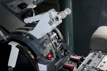
There is no mistaking the clarity and brightness of an OEM unit.  This is the Captain-side Master Caution System (MCS)

In my opinion, many simulators fall short when it comes to replicating the Master Caution System (MCS).  Most companies offerings are cheesy-looking in appearance, exhibit the incorrect colour hue, and lack the brightness seen is the OEM unit.  

This post will examine the use of Master Caution System and explain how the OEM items were fitted to the simulator and interfaced with ProSim737 avionics suite.  It will also briefly compare the real unit to the reproduction unit.

Click images for larger view.

Boeing Master Caution System (MCS) - Overview and Use

The Master Caution System (MCS) was developed for the Boeing 737 to ease pilot workload as it was the first Boeing airliner to be produced without a flight engineer. In simple terms the system has been designed to be an attention getter - the brightly illuminated version of a flight engineer’s 'barked' out commands…

The MCS comprises four annunciators (warning buttons) and two System Annunciator Panels (six packs) located on the Main Instrument Panel (MIP) in the glareshield on both the Captain and First Officer sides.  

The location of the annunciators and the intensity of illumination is important.  If an annunciator should illuminate, the positioning and brightness is such, that there is minimal possibility of a flight crew ignoring the warning.  Whilst the warning buttons are duplicated on both sides of the MIP, the annunciation panels provide different 'cautions' for the Captain and First Officer.  

Fire Warning and Master Caution annunciators showing The detailed engraving on the legends

Fire Warning (Fire Warn) Annunciator

If a fire is detected in the APU, main gear well, cargo compartment or during a fire warning (or system test) in either engine, the Master Fire Warning annunciator (button) will illuminate RED.  The fire bell, and if on the ground the remote APU fire warning horn will also activate.  

Depressing the button from either the Captain or First Officer's side with a firm push will extinguish the button’s light and silence the audible fire bell and APU warning horn, in addition to resetting the system for additional warnings.  Pushing the fire warning bell cut-out switch on the overheat/fire protection panel (fire suppression module or fire handles) accomplishes the same action.

Master Caution Annunciator

The Master Caution annunciator (button) is coloured AMBER.  The button will illuminate when a system annunciator (six pack) has been triggered indicating a fault has been detected within the aircraft systems.

Depressing the button with a solid push (Captain or First Officer side) will extinguish the button’s light and reset the system for additional master caution conditions.

System Annunciator Panel ('six packs')

There are two System Annunciator Panels, one on the Captain side and one on the First Officer side.  Each light plate has six different AMBER coloured 'cautions' which are arranged such that the 'cautions' are in the same orientation as the overhead panel.  For example, FUEL is bottom left.  

Components of the Master Caution System:  Two duplicated Fire Warning and Master Caution buttons and the two System Annunciator Panels (six packs).  The diagram shows the various cautions that a flight crew can expect to observe (image copyright FCOM).  The MCS is identical for all Boeing series airframes 600 through 900 including the Boeing Business Jet (BBJ)

The display annunciations relate a specific aircraft system.  The following are displayed on the Captain-side panel: FLT CONT, IRS, FUEL, ELEC, APU and OVHT/DET.  The displays for the First officer side panel are: ANTI-ICE, HYD, DOORS, WNG, OVERHEAD and AIR COND.

If a master caution condition exists, the Master Caution light will illuminate AMBER along with the appropriate system annunciator.  Likewise, if a caution exists and is displayed on either six pack the Master Caution button will illuminate.

To extinguish the System Annunciator display, the Master Caution button should be firmly depressed.

Self-Test and Recall

The System Annunciators have a self-test and recall function.  Firmly pressing and holding either light plate will cause all annunciation lights to display (self-test).   To recall the last displayed 'caution', the light plate is pressed once and released.  After release the system annunciator will display whatever "caution" was last detected.

There is little argument that the OEM Master Caution System exceeds the quality of reproduction units.  This is the MCS from a top shelf manufacturer.  Compare thsi with the OEM counterpart. Reproduction units could be easily improved if they used a number of high intensity LEDS aligned in an array so that the light had better coverage

Reproduction Verses OEM

Broadly speaking, there is a large gap in quality between reproduction MCS units and the OEM version.  

For the most part, reproduction annunciators are very easy to depress - a tap of a finger will deactivate a warning or recall a ‘caution’.  The legend is printed rather than lazer engraved and the colour of the light is often an incorrect colour hue which lacks the brightness of the real unit.  The last point is caused by low voltage LEDs which are not bright enough and do not have an adequate throw of light to illuminate all of the legend.  Furthermore, reproduction units are for the most part made from plastic, rather than longer lasting aluminium.

This said, some highly priced units do replicate the OEM part very well but they do cost upwards of $450.00 USD (see Fly Engravity).

In contrast, the OEM unit has engraved legends that are very distinct and easy to read, require a firm press to engage, and are very bright.  OEM units use 28 Volt bulbs which burn very brightly.

Not Just A Finger Tap - Firmness in Operation

An OEM annunciator requires a bit more force to depress the button in comparison to a reproduction unit.  I'm uncertain if this is due to the strength or weakness of the internal spring mechanism or as I've been lead to believe, is a built-in safety feature; thereby minimising the chance of a flight crew accidentally depressing and cancelling an annunciator ‘caution or warning’ with a light tap or brush of the of the finger or hand.

Classics Verses Next Generation (NG)

Both airframes incorporate the Master Caution System; however, the classics use different display cautions for the system annunciators. I believe there are five 'cautions' on the classic in contrast to six on the NG (600, 700, 800 & 900).  The fire and master caution annunciators are identical on all Boeing airframes.

Interfacing and Power Requirements

To interface the unit requires a Phidget 0/16/16 interface card while the power to illuminate the bulbs is from a 28 Volt power supply.  A 0/16/16 card provides 16 inputs and 16 outputs which allows complete coverage of all functions remembering some functions duplicated on the Captain and First Officer-side have wires placed into the same input terminal. The duplicated items are the fire and master caution annunciations.

Each of the four annunciators has three terminals.  A multimeter set to conductivity or beep mode is used to determine which terminal connects to which button press. 

  • To learn how to use a multimeter, read this article.

The System Annunciator Panel (six pack) is a little more convoluted as it has a recall facility and has different cautions between the Captain and First Officer units.  However, with a little diligence it’s possible to work out the terminal and wiring sequence.

Anatomy of a System Annunciator (akasix pack)

Each unit is made up of three parts:  the actual annunciator, the light plate (which incorporates the legend), and a rectangular housing that I call the cigarette packet. The housing is attached to the annunciator by two hex screws.

Light plate removed from housing and rear terminals.  Note individual pins for specific display cautions and "clam shells" for connection

The light plate has a number of pins that connect with the annunciator base, and on the rear there are eight terminals (lower image) each connecting with a specific terminal.

If you remove the outer casing, a circuit diagram has been stenciled to the unit.  It’s trial and error using this diagram to determine the correct pin outs for the terminals, but once known it’s only a matter of connecting the various wires from the the terminals to the 0/16/16 card.

Eight terminals.  The outer edge of the hex nut can easily be observed on the upper left side of the annunciator

It’s important to note that if removing or loosening the outer cigarette-style housing, a hex screw located at the corner edge of the unit will need to be loosened. 

Phidgets 21 Manager

The Phidget 21 Manager is provided by Phidget and can be downloaded from their website.  This software will, when a Phidget card is connected, register that card and its distinctive number. 

Opening the Manager and then selecting the card number ID tag will allow you to see what inputs and outputs you have wired and assigned to whatever item you have connected.  You will also be able to easily test any output.

Configuring in ProSim737

Once the pin outs have been correctly determined, configuring in ProSim737 is very easy.  Open the configuration tab and select the indicators menu (tab).  Next find the appropriate names (DOORS, ELEC, APU, ANTI-ICE, etc) and in the drop down box assign the correct Phidget card and output number.

Installing to the Glareshield

Main Instrument Panels (MIPS) manufactured by different companies are rarely identical; each MIP has subtle differences – some are easier to install OEM items to than others.

Detail of Master Fire Warning annunciator showing manufacturer name and threaded button with hexagonal attachment nut.  different manufacturers produce slightly different shaped bodies

Reproduction annunciators are usually secured to the glareshield by screws; however, OEM parts often require retrofitting to allow the item to be fitted correctly. 

In the case of the FDS MIP, a backing plate made from ABS plastic was crafted to fit into the gap where the fire warning and master caution buttons reside; the plate was secured to the glareshield by self-tapping screws.

Two holes were then carefully drilled at the correct distance to allow the circular shaft of each button to be fitted through the plastic.  Once the button was sitting proud in the correct position, the screw and nut assembly was tightened against the backing plate.  

The annunciators are not designed to sit neatly side by side in the glareshield; they can be twirled to any orientation; therefore, it’s not necessary to be perfect in the alignment of the drill hole – just very close!

Securing the system annunciators to the MIP was slightly more problematic and involved using a spacer between the outside of the housing and the gap in the glareshield.  The spacer expands as you push the six pack into position, and it’s a matter of enlarging the spacer to secure the unit in the correct position.  This said, the method used is not optimal and a more secure method needs to be developed.

Video (Captain-side only)

A short video demonstrates the brightness of the buttons and display cautions.

The annunciator light plate displayed in the video is not in the best condition; it is common for airlines to place clear tape over the legends to protect them.  This did not concern me at the time, as six packs are scarce to find.  However, I have since found four buttons in better condition and will soon exchange them.

  • For those interested, to silence the fire bell in the video, I used the bell cut-out switch on the fire suppression module rather than depressing the Fire Warning Annunciator, which would have accomplished the same task.


737 Master Caution System and six packs

Acronyms and Glossary

  • Annunciator – A single coloured light or group of lights used as a central indicator of status of equipment or systems in an aircraft. Usually, the annunciator panel includes a main warning lamp or audible signal to draw the attention of operating personnel to the annunciator panel for abnormal events or conditions.  To annunciate means to display or to become audible.  Annunciators often are called KORRYS (KORRY is the name of a manufacturer).

  • Cautions – Annunciations from the System Annunciation Panel in amber colour.  For example, DOORS, APU and ELEC.  An annunciation 'caution' triggers the Master Caution Warning light.

  • FDS – Flight Deck Solutions

  • Light Plate - the actual forward portion of the annunciator separated from the rear section and the housing.

  • Legend – The portion of the light plate that includes the engraved display (for example, ELEC or DOORS)

  • MCS – Master Caution System incorporating: Fire Warning, Master Caution Warning and two annunciator panels (six packs)

  • MIP – Main Instrument Panel

  • OEM – Original Equipment Manufacture (real Boeing part)

  • Phidget 21 Manager – Configuration software to use a Phidget card

  • 'Six Pack' – Nickname for System Annunciator Panel

  • System Annunciator Panel (SAP) – Light plate with six 'cautions' and recall facility (NG only).  Also known as 'six pack'

Update

UPDATE ON 2015-07-29 13:10 by FLAPS 2 APPROACH

Captain side straight-through cable connector mounted beneath the glare wing. The colour-coded internal wiring of the lumen can be seen.

The white terminal block facilitates connection of the the MCS with the Lights Test functionality (Lights Test toggle located on the MIP).  To the terminal block, a wire connects directly to a Lights Test Busbar located in the center pedestal.  The busbar then connects directly with the OEM lights test toggle switch. The brackets are made from ABS plastic

In June 2015, the wiring design for the simulator was changed, and the annunciators were rewired to facilitate conformity with the wiring of other OEM parts.  The Captain and First Officer annunciators were separated and wired directly to a Phidget 0/16/16 card. 

To ensure that the wiring was easily identified, wiring for the Master Caution System was color-coded to avoid any confusion with the wires that have been used to wire the AFDS units.

The new wiring design called for each MCS to be independently wired and separated from the other.  Each system has the wires budded into a dedicated, colour-coded lumen which is then connected to a serial port connector mounted to a bracket.  The bracket is attached to the underside of the glare wing at the rear of the MIP glareshield.  The connectors have straight-through cables that snake behind the MIP to mate with their respective connectors on the SMART module.

B737-800 NG Fuel Flow Reset Switch - OEM Switch Installed and Functional

oem 737-800 fuel flow switch can clearly be identified by its bulbous head.  I have observed that on some air frames this switch has a cross hatch design

I have replaced the reproduction Fuel Flow Reset Switch (FFRS) with an OEM switch.  I was not happy with the reproduction switch, which did not function correctly or look anything like the real switch used in the aircraft; the genuine switch is spring-loaded, quite large, and has a bulbous head.  The FFRS is a new switch which was probably destined to be installed into a Boeing Next Generation aircraft.

FFRS Functionality

The Fuel Flow Reset Switch resides on the center forward panel immediately above the central display unit on the Main Instrument Panel (MIP).  The function of the FFRS is to provide information on the fuel flow and fuel used.  The fuel flow/used indications are displayed on the lower display unit (depending on your avionics set-up preferences). 

The switch is a one-pole spring-loaded two-stage three-way momentary toggle switch.  The normal 'resting' position of the switch is in the central (RATE) position.  In this position the display unit indicates the fuel currently being used.  Pushing the switch downwards to (USED) changes the display indication to read the fuel that has been used.  Pulling the bulbous knob towards you whilst simultaneously pushing the switch upwards (RESET) resets the fuel used to zero.  The downward and upward throw of the switch is momentary which means that when the switch is released it will automatically return to its central "resting" position.

The reason the switch is two stage for upwards deployment (pull and push upwards) is for safety; a flight crew cannot inadvertently push the switch to the upwards position resetting the fuel used.

Installation and Wiring

Depending upon what MIP you are using, installation of the switch may require enlarging the circular hole in the MIP. This is to enable the shaft of the OEM switch to fit through the MIP frame and the light plate of the Center Forward Panel.  If the hole must be enlarged, care must be taken to not damage the light plate. 

If the MIP you are using is 1:1 ratio, then the switch should fit through the hole perfectly.  The switch is secured behind the light plate with a hexagonal nut.  This switch fits the FDS MIP without need for enlarging the hole.

The rear of the FFRS has three standard-style screw post connections, each connection being either positive, negative or common (earth).  To determine which throw of the switch does what, it’s necessary to use a multimeter set to continuity (beep mode).  Place the black probe of the multimeter on the central screw post and then place the red probe on either of the other two screw posts.  When you move the switch you will hear an audible beep indicating that function is “active” for that screw post.

diagram 1; fuel flow switch display indications (copyright Boeing fcom)

Interfacing

An I/O card is required for the switch to interface with the avionics suite.  A PoKeys card will suffice; however, I have used a Phidget 0/16/16 card; this card is installed in the SMART module.  This card has been used primarily because it had unused inputs.

Establishing the correct functionality is done within the flight avionics software.  If using ProSim737 it’s a matter of finding the fuel flow switch functions within the switches section of the configuration menu and assigning them.  Failing this FSUIPC can be used.

The FFRS is but a small item; however, many small items make a sum.  By using an OEM switch, you have the correct functionality of the switch in the simulator, and you improve the aesthetics.

The serial/part number for the switch is: MS-24659-27L, or for the non military specification 1TL1-7N.

Acronyms and Glossary

  • FFRS – Fuel Flow Reset Switch (also known as the Used Fuel Toggle)

  • OEM – Original Equipment Manufacturer

  • MIP – Main Instrument Panel

  • Momentary Switch - a switch which can be pushed downwards or upwards and when released returns to a central "resting" position

  • Two-Stage Switch - A switch that requires two events to activate the switch.  For example, simultaneously pulling and pushing upwards on the switch

B737 Throttle Quadrant - Trim Wheels and Trim Indicator Tabs

Captain-side trim wheel and trim tab indicator.  I was fortunate that the throttle unit I aquired retained its light plates in excellent condition.  It's not uncommon to find that the light plates are faded, scratched and cracked from removal of the unit from the aircraft

This post, the third last concerning the throttle quadrant conversion, will discuss the spinning of the trim wheels and movement of the trim tab indicators; both integral components of the throttle quadrant.  For a list of articles about the conversion of the throttle quadrant, see the bottom of this page.

1:  TRIM WHEELS

The trim wheels were implemented by Boeing in the mid 1950’s with the introduction of the Boeing 707 aircraft and been a part of the flight deck ever since.  The main reason Boeing has continued the use of this system in contrast with other manufacturer, who have removed the spinning trim wheels is redundancy.  Boeing believes that the flight crew should have the ability to manually alter trim should a number of cascading failures occur.

Whatever the reason for Boeing continuing with this older style technology, many flight crews have learnt to “hate “ the spinning trim wheels.  They are noisy and distracting, not to mention dangerous if a flight crew accidentally leaves the handle in the extended position; there is a reason that they are called “knee knockers”.  

Many virtual pilots are accustomed to using manual trim when flying a Cessna or a small twin such as the King Air.  In such aircraft altering trim by hand is straightforward and a necessary part of trimming the aircraft.  However, a jet such as the B737 it is a tad different; to alter the trim by hand would require the flight crew to manually rotate the trim wheels several dozen times to notice any appreciable result in trim.  As such, the electric trim switches on the yokes are mainly used to alter trim.

Motors, Interface Cards and Speed of Trim Wheel

The power to spin the trim wheels comes from two 12 Volt DC pump motors installed within the throttle unit.  A Phidget High Current AC Controller card is used to interface the trim wheels to the flight avionics software (proSim737). The cards are located in the Interface Master Module (IMM) and connected to the throttle unit by customised VGA cables.

The trim wheels can spin at two speeds.  The autopilot producing a different speed to that of manual trim (no automation selected).  A Phidget card is used to control the variability, with each of the two channels programmed to a different speed.  To alter the actual revolutions of the trim wheel, each channel is accessible directly from within the ProSim737 software configuration.   

To allow the trim system to be used by CMD A and/or CMD B, a second card is installed to ensure duplicity.  

Correct Timing

The trim wheels have white longitudinal line painted on each trim wheel.  This line serves two purposes: as a visual reference when the trims wheels are spinning, and to determine the number of revolutions per second during calibration.  To ascertain the correct number of wheel revolutions per second, a digital tachometer is used in the same way a mechanic would tune an older style motor vehicle.

Out of interest, in manual trim, 250 revolutions of the trim wheels are necessary to move the trim tab indicators from full up to full down.

Two Speed or Four ?

The B737 has four different trim revolution speeds, each speed dependent upon the level of automation used and the radio altitude the aircraft is above the ground.

Although it is possible to program this logic into the Alpha Quadrant cards and bypass ProSim737 software entirely (closed system), it was decided not to as the difference in two of the four speeds is marginal and probably unnoticeable.  Further, the level of complexity increases somewhat programming four speeds. 

Autopilot mode rotates the trim wheels at a faster rate than when in manual trim.

Trim wheel removed showing heavy duty spline shaft

Trim Wheel Braking

The real 737 incorporates a braking mechanism on the trim wheels that inhibits wheel movement when there is no input received to the system from either the auto pilot or electric trim switches. The brake operates by electromagnetic radiation and is always on, being released when an input is received.  

An unsuccessful attempt was made to replicate this using two military specification high torque brake motors.   The motors incorporate a brake mechanism, but the torque was so high and the breaking potential so great, that when the brake was reengaging/disengaging there was a loud thud that could not be ignored.  Further, the motor became very hot when the brake system was engaged and vibrated excessively due to its high power rating.

At the time, a lower torque motor could not be procured and a decision was made to use the 12 volt pump motors.  Therefore; the trim wheels take an extra second or so to spin down – not a major imposition and barely noticeable when flying the aircraft..

Deactivating Trim Wheel Spinning

Most of my virtual flying is at night and noisy and vibrating trim wheels can easily aggravate others in the house attempting to sleep.  To allow easy disconnection of the trim wheels, I have configured the right side trim stabilizer toggle to cut the power to the trim wheels.  Although not authentic, sometimes minor alterations need to be made to a system to make it more user friendly.

2:  TRIM TAB INDICATOR MOVEMENT

The trim tab indicators are used as a visual reference to indicate to the flight crew the trim of the aircraft.  The trim and subsequent movement of the indicator tabs are activated either by depressing the electric trim switch on the yoke or by turning the trim wheels by hand.

Phidget Card

A Phidget Motor Controller Advanced Servo card and servo is used to control the movement of the two trim tab indicators, while the logic to activate the servo is directly from the flight avionics software.  The speed that the trim tabs move is set through ProSim737 (trim speed).

Aluminum tab connected to servo.  Servo is mounted behind aluminium plate.  You can just make out the screw wire between the servo and the tab

Hardware Modifications

To allow the servo to connect directly to the trim tab indicators, a small tab of aluminium was welded to the main trim tab shaft.  A thin screw wire was then connected from the servo to the tab to allow nay movement of the trim tab to be registered by the servo. 

Determining Accuracy

There is little point in implementing movement of the trim tab indicators if a high level of accuracy is not possible; therefore, it’s important that that the position of the tabs matches that of the flight avionics software and virtual aircraft.  To ensure positional accuracy and maintain repeatability the servo was calibrated throughout its range of movement and checked against the “virtual trim tab strip” that can be placed on the EICAS screen within the ProSim737 software.  

The short video below shows the smoothness in movement of the trim tab indicators.  You will note the TQ vibrates somewhat.  This is because I have yet to secure it to the platform.


Boeing 737 OEM Steering Tiller Installed

oem 737-400 steering tiller mounted to bespoke aluminium plate

The steering tiller is an often overlooked piece of hardware for many virtual flyers.  The steering tiller provides greater control of the aircraft during taxi operations, and if calibrated correctly works very well.

OEM B737-400 Steering Tiller

The tiller has been salvaged from a 737-400 series aircraft and is identical to the tiller used in the Next Generation aircraft.  The actual OEM part is only the black handle and white arrow.  The remainder of the unit has been custom fabricated to allow easy attachment to the inside wall liners of the flight deck.

The simulator does not have a shell and liner at the moment; therefore, I've attached two pieces of grey-coloured wood to the unit to enable temporary installation to the forward left of the Captain's seat.  

A single potentiometer has been used allow calibration of the tiller mechanism.  A metal strip connects the potentiometer with a metal plate that connects to the the central area of the tiller mechanism.  As the steering tiller is turned left or right, the metal plate moves to and fro with a corresponding movement in the metal strip which registers on the potentiometer (see picture).

To create tension when the steering tiller is moved, several heavy duty springs have been used.  Although rudimentary in design, the tension of the springs provides a reasonable and constant pressure.  The springs also allow the handle to center itself easily when released.  Springs are renowned for creaking when they move and to remove this noise, heavy duty lithium grease has been applied to the upper parts of the spring heads where they join the metal. 

Tiller mechanism showing springs and potentiometer.  A linear potentiometer has been used in favour of a rotary potentiometer. Springs provide tension to center the tiller

Interface Card and Calibration

The tiller is connected directly to a Leo Bodnar BU086A interface card, although any joystick card such as a PoKeys card can be used.  A USB cable then runs from the interface card to the main computer.  To allow easy connection to the interface card (Leo Bodnar card) a female JR servo wire security clip has been used.  

The steering tiller requires careful calibration if it's to operate correctly.  Calibration is initially through Windows and then FSUIPC.  Using FSUIPC enables greater accuracy to be achieved.

The steering tiller, when calibrated through FSUIPC does not create an independent tiller axis but piggybacks on the movement of the rudder axis.  The developer has ingeniously written code that enables the tiller to be activated when groundspeed is under 60 kias.  Above this speed the rudder is activated.

How to Calibrate the Steering Tiller

  1. Connect the interface card to the computer via the USB cable.

  2. Using Windows, calibrate the axis of the interface card (if using Windows 7 type into the search bar joystick and select "Joystick Calibration").

  3. Following the on screen instructions, move the steering tiller handle forward and aft.  Then save the setting.

  4. Open Flight Simulator and then open “Settings/Control” in the FSX menu.

  5. Ensure that any joystick commands relating to the interface card are not registered by FSX.  If so, delete them and save.

  6. Open Flight Simulator and then open FSUIPC settings.

  7. Select the FSUIPC “Axis Assignment Tab”.  Then move the tiller handle to activate the calibration software.  (you will observe the numbers moving).

  8. Select from the left side of the screen the tab that says ”Type of Action Required”,  Select "Send Direct to FSUIPC Calibration".  Then open the menu box and scroll down to “Steering Tiller”.

  9. Open the “Joystick Calibration” tab in FSUIPC.  

  10. Scroll through the 11 entries searching for steering tiller (9/11).  When "Steering Tiller" is found, click the SET button which will open three (3) further buttons.  Each button refers to a position on the steering tiller axis.

  11. Turn the steering tiller to the left and click the RIGHT button.  Then turn the tiller to the right and select the LEFT button.  With the tiller in the central position click the MIDDLE button.  Oddly, on some setups the opposite is required.  If calibration fails, try again using the opposite direction.

  12. For more precise and accurate calibration, you may want to use the "Slope" and/or "Null Zone" functionality.

The steering tiller should now be calibrated and ready for use.

Troubleshooting and Suggestions

Some known problems that are easily solveable are:

A:  Only use the steering tiller at very low ground speeds.  If you turn the tiller to the full left or right and the speed is too great, the aircraft may remain stationary or slip; the reason being the nose wheel is locked at a right angle to the direction of travel.  I find the tiller works best turning the handle slowly.

B:  The direction of aircraft travel is opposite that of the tiller handle.  If this occurs, check your FSUIPC settings.  You may have to tick (check) the box that says REV.  REV reverses the direction of the axis (left to right and right to left).

C:  If the tiller exhibits sensitivity issues or if you require a dead zone, open FSUIPC and program the SLOPE function and/or set a NULL ZONE.

D:  If you have issues with the tiller not working correctly, do the calibration again in Windows and FSUIPC.  If calibrated correctly, the tiller will change to rudder control at 60 knots.

OEM is an acronym for Original Equipment Manufacturer.

B737 Throttle Quadrant - Speedbrake Conversion and Use

oem 737-500 throttle quarant speed brake lever

The speedbrake serves three purposes: to slow the aircraft in flight (by incurring drag), to slow the aircraft immediately upon landing, and to assist in the stopping of the aircraft during a Rejected Takeoff (RTO).  

There are four speedbrake settings: Down (detent), Armed, Flight Detent and Up. 

In addition, there are three speedbrake condition annunciators (lights), located on the Main Instrument Panel (MIP), that annunciate speedbrake protocol.  They are: Speedbrake Armed, Speedbrakes Do Not Arm and Speedbrakes Extended.  These annunciators (lights) illuminate when certain operating conditions are triggered.

This article is rather long as I've attempted to cover quite a bit of ground.  The first part of the post relates to technical aspects while the second portion deals with conversion.  Hopefully, the video at the end of this post will help to clarify what I have written.

Technical Information

Speedbrakes consist of flight spoilers and ground spoilers. The speedbrake lever controls a 'spoiler mixer', which positions the flight spoiler power control unit (PCU) and a ground spoiler control valve.   The surfaces are actuated by hydraulic power supplied to the power control units or to actuators on each surface.

Ground spoilers operate only on the ground, due to a ground spoiler shutoff valve which remains closed until the main gear strut compresses on touchdown (this is activated by the squat switch).

In Flight Operation

Actuation of the speedbrake lever causes all flight spoiler panels to rise symmetrically to act as speedbrakes.  The lever can be raised partly or fully to the UP position.  This causes the extension of the flight spoilers to the equivalent full up (ground spoiler) position.

Ground Operation

All flight and ground spoilers automatically rise to full extension on landing, if the speedbrake lever is in the ARMED position and both throttle thrust levers are in IDLE. When spin-up occurs on any two main wheels, the speedbrake lever moves to the UP position, and the spoilers extend.

When the right main landing gear shock strut is compressed, a mechanical linkage opens a hydraulic valve to extend the ground spoilers.  If a wheel spin-up signal is not detected, the speed brake lever moves to the UP position, and all spoiler panels deploy automatically after the ground safety sensor engages in the ground mode.

After touchdown, all spoiler panels retract automatically if either throttle thrust lever is advanced. The speedbrake lever will move to the DOWN detent.

All spoiler panels will extend automatically if takeoff is rejected (RTO) and either reverse thrust lever is positioned for reverse thrust. Wheel speed must be above 80 knots in order for the automatic extension of the spoilers to take place.

A failure in the automatic functions of the speedbrakes is indicated by the illumination of the SPEEDBRAKE DO NOT ARM Light. In the event the automatic system is inoperative, the speed brake lever must be selected manually placed in the UP position after landing by the pilot not flying.

Movement of Speedbrake Lever

The logic relating to the position of the speedbrake lever is:

DOWN (detent)

  • All flight and ground spoiler panels are in the closed position.

ARMED  

  • Automatic speedbrake system armed.

  • Upon touchdown and activation of the squat switch, the speedbrake lever moves to the UP position and all flight and ground spoilers are deployed.

FLIGHT DETENT

  • All flight spoilers are extended to their maximum position for inflight use.

UP

  • All flight and ground spoilers are extended to their maximum position for ground use.

Illumination of Speedbrake Condition Annunciators (korrys)

The logic relating to the illumination of the annunciator condition lights is:

Speedbrake Armed Annunciator

  • The light will not illuminate when the speedbrake lever is in the DOWN position.

  • The light illuminates green when the speedbrake is armed with valid automatic system inputs.

Speedbrake Do Not Arm Annunciator

  • The light will not illuminate when the speedbrake lever is in the DOWN position.

  • The light indicates AMBER if there is a problem (abnormal condition).

  • The light will illuminate during the landing roll following through 64 KIAS provided the speedbrake lever has not been stowed.  The light will extinguish when the aircraft stops or when the speedbrake lever is stowed.

Speedbrakes Extended Light

  • The annunciator illuminates AMBER pursuant to the following conditions.

In Flight

  • Amber light illuminates if speedbrake lever is positioned beyond the ARMED position, and

  • TE flaps are extended more than flaps 10, or

  • Aircraft has a radio altitude (RA) of less than 800 feet .

On The Ground

  • Amber light if the speedbrake is in the DOWN (detent) position.

  • Amber light if the ground spoilers are not stowed.

It is important to remember that the speedbrakes extended annunciator will not illuminate when the hydraulic systems A pressure is less than 750 psi.

Simulator Operation - What Works

  • Rejected Take Off (RTO) after 80 knots called - Activation of either reverse thrust lever and throttle to idle will extend spoilers (if RTO armed).  Lever moves to UP position on throttle quadrant.

  • Spoilers extend on landing when squat switch activated, throttles are at idle and lever is in armed position (3 requirements).  Lever moves to UP position on throttle quadrant automatically.

  • Spoilers extend automatically when reverse thrust is applied (if not previously armed - see above).

  • Engaging thrust after landing automatically closes spoilers.  Lever moves to DOWN position on throttle quadrant.

  • Speedbrakes extend incrementally in air dependent upon lever position (flight detente).

Speedbrake Logic - Alpha Quadrant Card and Closed-loop System

The logic for the speedbrake is identical to that found in the real Boeing aircraft and is 'hardwired' into the Alpha Quadrant card.  This card is located in the Interface Master Module (IMM) and is connected to the throttle quadrant by a custom-wired VGA cable.  Programming the Alpha Quadrant card is by stand-alone software.

The speedbrake system is a closed-loop system, meaning it does not require any interaction with the ProSim737; however, the illumination of the korry condition lights are not part of this system and therefore, require configuration in ProSim737  (a future update may include the condition korrys within the system). 

Conversion

A common method to convert the speedbrake is to use a potentiometer and then calibrate using FSUIPC (Flight Simulator Universal Inter-Process Communication).   Whilst this method is valid, it relies very much on FSUIPC to determine the accuracy of the visual position of the speedbrake lever.  The longevity of the system also very much depends upon the potentiometer used, its +- variance at time of manufacture and its cleanliness.  I wanted to move away from a potentiometer and FSUIPC and develop a more reliable and robust system.

Micro-buttons Replace Potentimeter

In the real Boeing 737 aircraft, a number of buttons reside beneath the arc that the speedbrake travels along.  As the speedbrake lever moves accross a button a condition is set.  If you slowly move the speedbrake level, and listen carefully, you can hear the switch activate as the lever moves over it.

This system has been replicated as closely as possible, by attaching a series of micro-buttons to a half-moon shaped arc made from aluminum.  The arc is installed directly beneath the speedbrake lever’s range of movement.  There are six micro-buttons installed and each button corresponds with the exact point that a function will be activated when the speedbrake lever moves over the button. 

The benefit of using buttons rather than a potentiometer is accuracy and reliability.  A button is on or off and there is little variance.  A potentiometer on the other hand has considerable variance in both accuracy and reliability.

In addition to the micro-buttons, there are two on/off buttons (read below) located on the forward bulkhead that control the arming of the speedbrake lever.

Relay Card

The micro-buttons are then connected to a Phidget 0/0/8 relay card (4 relays) that, depending upon the position of the speedbrake lever, turn on or off the programmed speedbrake logic.  The Phidget 0/0/8 relay card is located in the Interface Master Module (IMM). 

Basically, the system is a mechanical circuit controlled by micro switches that reads logic programmed into the Alpha Quadrant cards.  Because it’s a closed mechanical loop system, logic from the avionics suite (ProSim737) is not required.  Nor, is calibration by FSUPIC.

micro-button on speed brake lever

Arming the Speedbrake - The Detail

To arm the speedbrake, two micro-buttons, located forward of the throttle bulkhead and attached to a solid piece of metal are used.  Connecting the lower end of the speedbrake lever to the clutch assembly is a green coloured rod.  The rod is the linkage that moves the speedbrake lever.  Adjacent to this rod is a cylinder made from aluminum used to open or close the arming circuit.

As the speedbrake lever is brought into the arm position, the cylinder is moved until it touches either of the arming on/off button-switches.  

The cylinder will stay in the armed position until voltage is provided to the motor to move the speedbrake lever, which in turn moves the rod and cylinder. 

Power is sent to the motor in only two circumstances: when the aircraft lands and the squat switch is activated, or during a Rejected Takeoff (RTO).

The motor powering the movement of the lever is the angled motor. The two arming button switches can be seen, one is red the other black, while the rod, clutch assembly and cylinder can easily be identified.

motor and speed brake clutch assembly on forward part of throttle quadrant

Motor

Most enthusiasts use a servo motor to control the movement of the speedbrake lever.  I used a servo motor on my first TQ and was never satisfied at the speed the lever moved; it was always VERY slow and seemed to lack consistent power.

In this conversion a DC electric motor, previously used to automobile power electric windows was used.   The advantage in using a motor of this type is its small size, strong build quality and high torque output.  This translates to more than enough power to mobilize the speedbrake lever.  The motor is mounted to the front of the throttle bulkhead.

Clutch Assembly

The purpose of the clutch is to enable the movement of the motor’s internal shaft to be transferred to the rod which moves the speedbrake lever.  The clutch is fitted with a synthetic washer and a torque nut either loosens or tightens the clutch to either increase or decrease the drag pressure on the speedbrake lever (see photograph).  

Speedbrake Lever Movement - Variable Voltage to Control Speed

The speedbrake lever in the real B737 moves rather slowly when the lever is powered.  Traditionally, this slow movement has been cumbersome to replicate; the movement of the lever either being too slow or too fast.  

Below is a short video showing the speed that the speedbrake lever moves on a real Boeing 737-800 (courtesy & copyright to 737maint U-Tube).  Apologies for the adverts which I can not remove from the embed code.


Altering the Speed of Lever Movement

You will note that the lever movement is speed-controlled in both directions (forward and aft).  Whilst controlling the speed of the lever during landing is relatively easy, controlling the speed of the lever as it is stowed (down) is more difficult.  At this time I have not attempted to control the later speed.

Variable Voltage - 12 Volts

If you provide 12 volts directly to the motor, the lever will move very fast in a movement I have coined the 'biscuit cutter'.  However, if you lower the voltage that is provided to the motor, the speed of the lever will slow.  The crux of the issue is if you provide a voltage that is too low the lever will not move and if the voltage is too high you have a 'biscuit cutter'.   There has to be enough voltage for the motor to provide power to start the movement of the lever and rod. Further, the power must be strong enough to be able to push the cylinder past the on/off switch when the speedbrake is armed and deployed (down), or is being closed (up) when throttles are advanced (after touchdown).

Two Methods  & Troubleshooting Potential Problems

I examined two methods to reduce the speed of the lever movement.

The first method uses a commercially manufactured reducer to lower the voltage, to a level that allows the lever to move more slowly than if full voltage was supplied to the motor.  This is the more expensive, but probably the better method to use, as you know exactly what voltage the motor is receiving after the reducer is connected.  Reducers can be purchased that reduce voltage by a known amount.

The second method takes advantage of voltage-reducing diodes and resisters to minimize the voltage coming directly from the relay card (the power connects directly to the relay card).  Although simplistic and less expensive than a reducer, it can be troublesome to determine the correct voltage reduction after the diodes or resisters are installed.  

As stated above, 'too little voltage and the lever will not move or move at a snail’s pace; too fast and your cutting biscuits… '

Although diodes and resisters were used, I believe using a reducer is probably more effective.  Using the former method involves educated 'guesswork'  to how much voltage is needed to start the movement of the lever.  I believe a reducer may provide a more measurable approach.

The speed that the lever moves is not 'perfect', but is adequate in comparison to the speed that the lever moves in the real aircraft.  I'd like to implement the correct noise that can be heard when the speedbrake is moving.  The noise (heard in the above video) emanates from the hydraulic actuator that pushes the lever mechanism.

Illumination of Speedbrake Condition Annunciators (korrys) on MIP

As outlined earlier, there are specific operational conditions that dictate the illumination of annunciators on the Main Instrument Panel.

It’s not difficult to connect the condition lights on the MIP, to the actual position that the speedbrake lever is in.  To do so requires re-routing the wiring from the lights so that they illuminate at the correct setting as determined by the on/off micro buttons.   Connecting the condition lights completes the speedbrake circuit (movement and illumination) in a closed system separate to the avionics suite.

At the moment this has not been done.  As such, the movement of the lever is a closed system and the illumination of condition lights is dictated by ProSim737. 

Power Supply

The speedbrake motor is powered by a Meanwell S150 12 Volt 12.5 amp power supply.

Below is a video showing the movement and speed of the speedbrake lever.  The video also shows how the mechanism operates.  Disregard the lack of a lower display unit and the GoFlight panel.  The later is for testing purposes until I have installed a fully functional overhead panel.


737 throttle speedbrake movement test


Update

on 2020-07-11 09:55 by FLAPS 2 APPROACH

In June 2015 the speedbrake mechanism was changed to a mechanical system that is more reliable and provides a consistent output (works every time). 

The changes and improvements to the system can be read in this article: Throttle Quadrant Rebuild: Speedbrake Motor and Clutch Assembly Replacement.

B737-500 Throttle Conversion to NG Style - Overview

This is the second throttle unit I’ve owned and based on experience, there are many changes that have been implemented that are different to the earlier unit.

The throttle quadrant is a relatively complicated piece of kit.  To do it justice, rather than write about everything in one very long post, I’ve decided to divide the posts into sections.  

This is the first post that will deal with the general attributes of the throttle unit, interface cards used and touch on the automation and motorization of the unit.  Further detailed posts will address individual functionality, conversion and troubleshooting.

Historical Perspective and Conversion

The throttle quadrant and center pedestal were removed from an Alaskan Air Boeing 737-500 airframe.  I purchased the unit directly from the teardown yard in Arizona (via a finder).  

The conversion to full automation and motorization was not done by myself, but by a good friend of mine who is well versed in the intricacies of the B737 and in the various methods used to install automation to a throttle unit.  I am very fortunate to be friends with this individual as in addition to being an excellent craftsman with a though understanding of electronics; he is also a retired Boeing 737 Training Captain.

forward bulkhead of oem 737-500 throttle

New Design

The new throttle unit has been converted to Flight Simulator use based on a new design.  The interface cards, rather than being mounted on the forward bulkhead have been mounted within the Interface Master Module (IMM) which is separate to the actual throttle unit.  The DC motors required for throttle and speed brake motorization are mounted forward of the throttle unit (in the traditional location).  

Connection from the throttle to the IMM is via specially-adapted VGA cables and D-Sub plugs.  This keeps the unit clean of unsightly wiring and interface cards.  it also keeps loose cables and wires to a bare minimum on the outside of, and inside the unit; automation and motorization means that there are now moving parts and it’s important to separate delicate cards and wiring away from mechanically moving parts

This is in stark contrast to my first throttle that had the interface cards mounted directly on the forward bulkhead and within the unit.

In addition, micro buttons have been used in some circumstances to counter the traditional method of using potentiometers to control calibration of the speed brake, flaps and throttles.

Center Pedestal - Cabling and Wiring

The three-bay center pedestal, mounted directly behind the throttle unit, has a number of cables and connections required for individual panel operation.  Rather than have these cables weave through the mechanism of the throttle (remember this is an automated throttle and there is considerable movement inside the unit), I’ve opened a hole into the platform directly under the pedestal.  

Any wiring or cabling is routed through this hole into a piece of round flexible conduit tubing (it’s actually the hose from a disused washing machine). The cables, after making their way to the front of the platform, then connect either to the computer or the Interface Master Module.

The use of flexible tubing is not to be underestimated as any cabling must be protected to avoid the chance of snagging on the under-floor yoke and rudder mechanisms which are continually moving.  

Interface Cards

Conversion of any OEM part to operate within Flight Simulator requires interface cards.  The following cards are used to convert analogue outputs to digital inputs for the throttle unit.  The cards also provide functionality for the fire panel, landing gear, yaw dampener, flaps and brake pressure gauges on the Main Instrument Panel (MIP).  All cards are mounted on the separate Interface Master Module (IMM).

  • Alpha Quadrant Motor Controller card A - TQ automation & logic CMD A channel

  • Alpha Quadrant Motor Controller card B - TQ automation & logic CMD B channel

  • Phidget High Current AC Motor Controller card – Provides two channels for trim wheel speeds and trim wheel movement

  • Phidget Motor Controller Advanced Servo card – Provides the interface or bridging between the Alpha Quadrant cards and flight avionics and CMD A

  • Phidget Motor Controller Advanced Servo card - Provides the interface or bridging between the Alpha Quadrant cards and flight avionics and CMD B

  • Phidget Motor Controller Advanced Servo card – Movement of flaps gauge

  • Phidget Motor Controller Advanced Servo card – Movement of trim indicator tabs

  • Leo Bodnar BU0836 A Joystick Controller card – Controls all switches & buttons on TQ

  • PoKeys 55 card - Flaps (buttons)

  • Phidget 0/0/8 relay card – Speed brake, auto throttle relays CMD B, fire panels, trim wheel revolution speed on CMD B

  • Belkin 7 input USB 6.5 amp powered mini hub (2) – TQ

Phidget Cards

Phidgets cards provide the necessary interface between the throttle and flight simulator.  I believe that Phidget cards are probably one of the more reliable cards on the market that can be used to directly interface OEM parts to flight simulator.

In addition to the two Alpha Quadrant cards mentioned above, a Phidget High Current AC Controller card acts as a "bridge" to allow communication between the Alpha Quadrant cards and the avionics suite (in this case ProSim737).  This card also provides the connectivity to allow the trim wheels to spin when CMD A or B is selected on the Main Control Panel (MCP).

Trim Tab Indicators and Throttle Buttons

To control the movement of the two trim tab indicators, a Phidget Motor Controller Advanced Servo card is used to control the output to two, two-stage DC motors.  These motors, which are normally used to power water pumps, control the variable speed of the trim indicators and the revolution of the trim wheels.  The speed which the indicator moves is reliant on the user setting within the “trim section” in the configuration page of the flight avionics software.

A Leo Bodnar BU0836A Joystick Controller card is used to control all switches and buttons on the throttle unit, while a Phidget 0/0/8 relay card is used to turn logic on and off that controls the actions of the speed brake.  

white colour of next generation thrust levers is unmistakable

Automation

Essentially, automation is the use of CMD A or CMD B (auto pilot) to control the N1 outputs of the throttle, and motorization is the moving of the throttle levers in unison with N1 output.  

Automation is achieved by the use of two main motor controller cards (Alpha Quadrant cards); one for CMD A and another card for CMD B.   Each card operates separately to each other and is dependent upon whether you have CMD A or CMD B selected on the Main Control Panel (MCP).

The Alpha Quadrant cards provide the logic from which the automation of the throttle unit operates.  

Being able to program each card allows replication of real aircraft logic and systems.  Whenever possible, these systems and their logic have been faithfully reproduced..

Main Controller Cards (thanks NASA)

The controller card I have used is not a Phidget card but a specialist card often used in robotics (Alpha Quadrant card).  The software to program the card has been independently developed by a software engineer and does not utilize Phidgets.

The technology used in the controller card is very similar to that utilized by NASA to control their robotic landers used in the space industry.  The technology is also used to control robots used in the car industry and in other mass production streams.  One of the benefits of the card is that it utilizes a software chip that can be easily replaced, upgraded or changed.  

cp flight mcp

CMD A/B Auto Pilot - Two Independent Systems

Most throttle units only use one motor controller card which controls either CMD A or CMD B; whichever auto pilot you select is controlled by the same card.  

In the real aircraft to provide for redundancy, each auto pilot system is separate.  This redundancy has been duplicated by using two Alpha Quadrant controller cards, rather than a single card.  Each controller card has been independently programmed and wired to operate on a separate system.  Therefore, although only one CMD is operational at any one time, a completely separate second system is available if CMD is selected.

Synchronized or Independent Motorization

Synchronization refers to whether the two throttle thrust levers, based upon separate engine N1 outputs, move in unison with each other (together) or move independently.

In the real aircraft, on earlier airframes, the levers were synchronized; however, the NG has a computer-operated fuel control system which can minutely adjust the N1 of each engine.  This fuel management can be observed in a real aircraft whereby each throttle lever creeps forward or aft independent of the other lever.

Programming flight simulator to read separate N1 outputs for each engine and then extrapolating the data to allow two motors to move the throttle levers independently is possible; however, the outputs are often inaccurate.  This inaccuracy can be seen on reproduction throttle units that show huge gap between lever one and lever two when automating N1 outputs.  

I decided to maintain the older system and have both levers synchronized.  If at some stage in the future I wish to change this, then it’s a matter of adding another motor to the front of the throttle bulkhead to power the second thrust lever.

Although the TQ is automated, manual override (moving the thrust levers by hand) is possible at any time as long as the override is within the constraints of the real aircraft logic and that provided by the flight avionics (ProSim737).

pump motors provide the power to move the thrust levers and speedbrake

Motors

Four motors are used in the throttle unit.

Two electric motors are mounted forward of the bulkhead.  These motors power the movement of the throttle levers and speed brake.  Two DC pump motors are installed directly within the throttle unit and power the movement of the trim wheels and trim tab indicators.

A clutch system is also mounted to a solidly mounted frame on the forward bulkhead.  The clutch system is used by the speed brake.  The method of locomotion between clutch and thrust levers is a standard automobile style fan belt.  

To allow both thrust levers to move in unison, a bar linking the lever which is motorized to the non-motorized lever was fabricated and attached to the main shaft of the motor.  

The motors chosen were automobile electric window motors.  These motors are powerful, provide excellent torque and were selected due to their reliability and ease of use.

flight simulator using oem throttle

Trim Wheel Spinning

The trim wheels can spin at two different speeds dependent upon whether the auto pilot is engaged or whether automation is turned off (manual flying).  A Phidget High Current AC Controller card is used to interface the spinning of the trim wheels.  The Phidget card has two channels and each channel can be programmed to a different revolution speed.  The speed of the revolutions is controlled directly within the Phidget Advanced menu within the ProSim737 software.   

The system was duplicated using a second Phidget card to ensure that both CMD A and CMD B operated identically.

In the real aircraft there are four different revolution speeds dependent upon the level of automation and the radio altitude above the ground.  Although it is possible to program this logic into the Alpha Quadrant cards and bypass ProSim737 software, it was decided not to as the difference in two of the four speeds is marginal and probably unnoticeable.  Further, the level of complexity increases somewhat programming four speeds.

Trim Wheel Braking

In the real aircraft, the trim wheels have an effective braking mechanism that stops the trim wheels from spinning down; basically it’s a brake.  Testing of a military specification motor with brakes to stop wheel movement was done; however, the motors were too powerful and whilst the trim wheels did stop spinning, the noise and jolt of the brake activating was not acceptable.

Functionality and Configuration

The TQ has been converted to allow full functionality, meaning all functions operate as they do in the real Boeing aircraft. Speed brake, flaps, parking break, reverser levers, thrust levers, trim stabilizer runaway toggles, trim tab indications, TOGA and A/T buttons, horn cut out, fuel levers and two speed trim wheel spinning have been implemented.

These functions and the process of conversion and calibration (potentiometers and micro buttons) will be addressed in separate posts.

Configuration, if not directly to the Alpha Quadrant cards via an external software program is either directly through the avionics suite (ProSim737) and the Phidgets card software or through FSUIPC.  Where possible, direct calibration and assignments via FSX have not been used. 

oem 737-500 backlighting

Backlighting

The throttle unit's light plates, with the exception of the parking brake which is illuminated by a 28 Volt bulb, are back lit by 5 Volt aircraft bulbs.  A dedicated S150 5 Volt 30 amp power supply is used to supply power to the bulbs.

Stab Trim T-Locker Toggles

The only function which is different from the real aircraft is the stab trim switch.  The left hand toggle operates correctly for runaway trim; however, the right hand toggle has been configured that, if toggled to the down position, the trim wheels will stop spinning.  The toggle is a basic on/off circuit and stops current going to the motors that move the trim wheels.  

The reason for doing this is that I often fly at night and spinning trim wheels can be quite loud and annoying to non-flyers…  The toggle provides a simple and easy way to turn them on or off at the flick of a switch.

oem 737-500 t-lockesr

Finding T-Lockers

Finding T-Locker toggles that are used in the NG series airframes is not easy.  Reproduction units are available but they appear cheesy and rarely operate effectively as an OEM toggle.  Earlier airframes used metal paddles (my earlier 300 series throttle used these type of trim switches) while the 400 series uses a different style again.  Trim switches are usually removed and reinstalled into an aircraft; therefore, I was fortunate that the throttle unit I secured had the later model T-Lockers.

The switches are called T-Lockers as you must manually pull down the cover from each switch before pulling the toggle downwards.  This is a safety feature to ensure that the toggles are not inadvertently pushed by the flight crew.

Thrust Handles - Colour

The colour of the throttle quadrant between the 737 aircraft variants leading towards the Next Generation series is similar, however, the colours are slightly different on the Next Generation throttle are different.

First, the thrust levers are not painted, but are cast in the actual colour.  Despite this, older aircraft will exhibit UV fading causing the thrust levers to appear darker and yellower.

There is no distinct RAL colour, however, RAL 7047 is very close.  The colour of the thrust levers is identical to the side walls, knobs and liners.  The bac hex colour designation in BAC#705 (Federal STD 595B-36440).  If you do not understand the various colour definition, search google for further information.

Importantly, it is almost impossible to find the correct colour codes as Boeing guards this information carefully to ensure it is not copied by rival aircraft manufacturers (why I am not sure).

More Pictures (less words...)

In this post we have discussed a general overview of the throttle quadrant and examined the automation and motorization.  We also have looked at the interface cards used and studied the stab trim T-Lockers in more detail.  In future posts we will examine the different parts of the throttle unit and learn how they were converted and calibrated to operate with Flight Simulator.

Click any mage to make it larger.

  • UPDATED 16 August 2022