BRT / DIM Functionality - Lights Test Switch

Lights Test switch.  The three way switch located on the Main Instrument Panel (MIP) Captain-side is used to toggle the intensity of connected annunciators.  The panel label reads TEST, BRT and DIM.  The switch in the photograph is an OEM switch which has been retrofitted to a Flight Deck Solutions (FDS) MIP

The annunciators in the Boeing 737 are very bright when illuminated, and the reason for the high intensity is justified - the designers want to ensure that any system warnings or cautions are quickly noted by a flight crew.

However, when flying at night for extended periods of time the bright lights can be tiring on your eyes.  Also, during critical flight phases such as during a night-time approach, the bright lights can become distracting.  At this time, the flight deck is usually dimmed in an attempt to conserve night vision. 

For example, the three green landing annunciators (Christmas tree lights), speed brake and flaps extension annunciators are all illuminated during the final segment of the approach.  At full intensity these annunciators can, at the very least, be distracting.

To help minimize eye strain and to enable night vision to be maintained as much as possible, pilots can select from two light intensity levels to control the brightness output of the annunciators. 

Anatomy of the Lights Test Switch

The switch (a three-way toggle) which controls the light intensity (brightness level) is called the Lights Test switch.  The switch is located on the Main Instrument Panel (MIP).  The switch is not a momentary switch and whatever position the switch is left at it will stay at until toggled to another position.  The switch has three labelled positions: Lights Test, BRT and DIM. 

(i)           UP controls the lights test (labeled Lights Test);

(ii)          CENTER is the normal position which enables the annunciators to illuminate at full intensity (labeled BRT); and,

(iii)         DOWN lowers the brightness level of the annunciators (labeled DIM).

OEM annunciators have a built-in Push-To-Test function, and each annunciator will illuminate when pushed.  The brightness level is pursuant to the position the Lights Test switch (DIM or BRT). 

The Lights Test will always illuminate all the annunciators at their full intensity (maximum brightness). An earlier article explains the Lights Test switch in more detail.

Special Conditions

When the Light Test switch is set to DIM, all the annunciators will be display at their minimum brightness.  The exception is the annunciators belonging to the Master Caution System (MCS), which are the master warning, fire bell and six packs, and the Autopilot Flight Director System (AFDS).  These annunciators will always illuminate at their full intensity because they are construed as primary caution and warning lights.

Variable Voltage

There is nothing magical about the design Boeing has used to allow DIM functionality; it is very simplistic.

Annunciators for the most part are powered by 28 volts; therefore, when the Lights Test switch is in the neutral position (center position labeled BRT) the bulbs are receiving 28 volts and will illuminate at full intensity.  Moving the switch to the DIM position reduces the voltage from 28 volts to 16.5 volts with a correspondingly lower output.  In the real aircraft, the DIM functionality (and Light Test) is controlled by a semi-mechanical system comprising relays and zener-type diodes that vary the voltage. 

Two Controlling Systems - your choice

The DIM and Lights Test functionality can be achieved in the simulator by using one of two systems - software or mechanical.

Software Controlled

The avionics suites developed by Prosim-AR, Project Magenta and Sim Avionics have the ability to conduct a full Lights Test in addition to allowing DIM functionality.  However, depending upon the hardware used, the individual Push-To-Test function of each annunciator may not be functional.  The DIM functionality is controlled directly by the avionics suite software; it is not a mechanical system as used in the real aircraft.

In ProSim737 the DIM function can be assigned to any switch from the configuration/switches and indicators menu.  In Sim Avionics the function is assigned and controlled by FSUIPC offsets within the IT interface software.

Mechanically Controlled

I have chosen to replicate the Lights Test and DIM functionality in a similar way to how it is done in the real aircraft. 

There are no benefits or advantages to either system – they are just different methods to achieve the same result.

Two Meanwell power supplies are used to provide the voltage required to illuminate the annunciators.  A 28 volt power supply enables the annunciators to be illuminated at their brightest intensity, while the less bright DIM functionality is powered by a 16.5 volt power supply (or whatever voltage you wish).

A heavy duty 20 amp 12 volt relay enables selection of either 28 volt or 16.5 volts.

The DIM Board is surprisingly simple and comprises a single terminal block and a heavy duty 12 volt relay.  Wires are coloured and tagged to ensure that each wire is connected to the correct terminal

DIM Board

A small board has been constructed from ABS plastic on which is mounted a 20 amp 12 volt relay and a terminal block. The board, called DIM is mounted behind and beneath the MIP. This facilitates easy access to the required power supplies mounted within the Power Supply Rack (PSR)

An important function of the DIM board is that it helps to minimise the number of wires required to connect the DIM functionality to the various annunciators and to the Lights Test switch.   

Interfacing and Connections

Prior to proceeding further, a very brief explanation is required to how the various panels receive power. 

Rather than connect several panels directly to a power supply, I have connected the power supplies to two 28 volt busbars - one busbar is located in the center pedestal and other is attached to the rear of the MIP.  The busbars act a centralised point from which power is distributed to any connected panels.  This allows the wiring to be more manageable, neater, and easily traceable if troubleshooting is required.

Likewise, there is a lights test busbar located in the center pedestal that provides a central area to connect any panel that is lights test compliant.  Without this busbar, any panel that was lights test compliant would require a separate wire to be connected to the Lights Test switch in the MIP. 

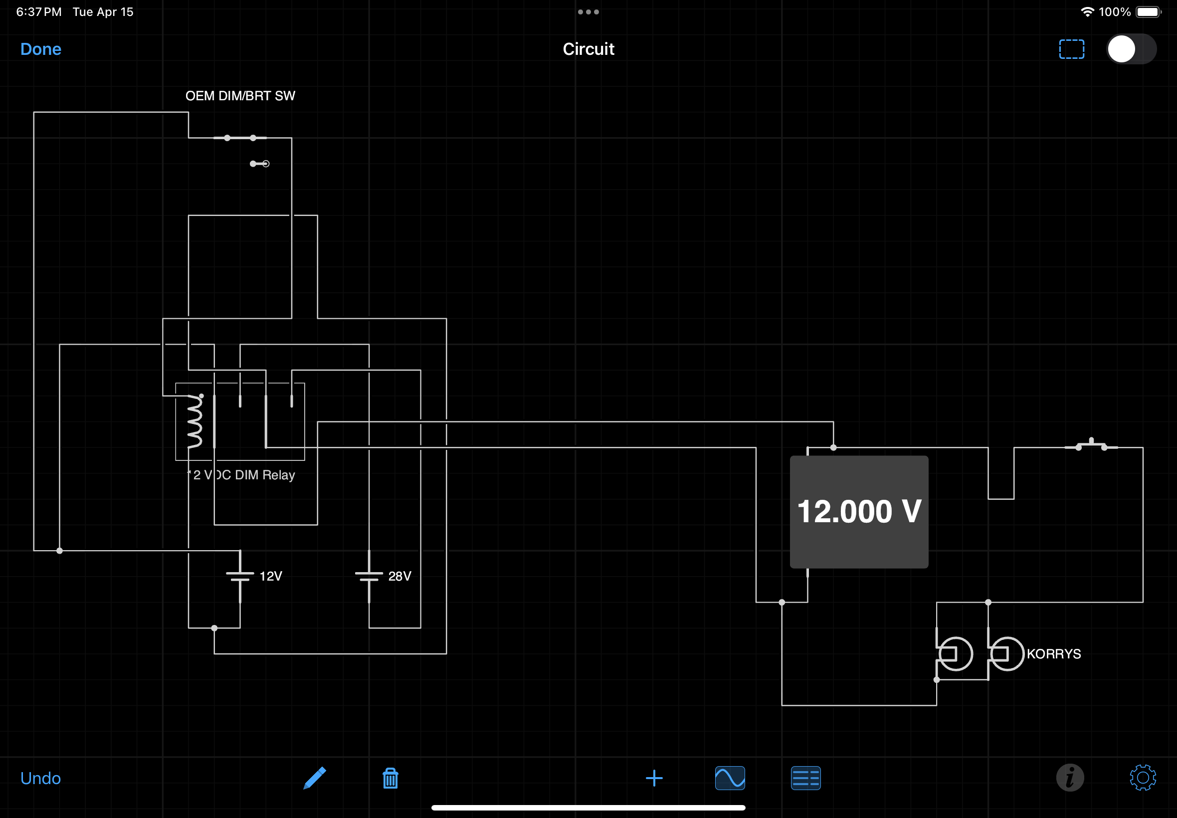
The below mud schematic may make it easier to understand.  To view the schematic at full size click the image.

Mud schematic.  Note that grey box should say 12 Volts - not 28 Volts

A 28 volt busbar located in the center pedestal is used as a central point from which to connect various panels to (lower pale blue box).  

The busbar is connected to the terminal block located on the DIM board.  Wires from the terminal block then connect to a 16.5 and 28 volt power supply located in the PSR (orange boxes). 

The relay is also wired directly to the terminal block on the DIM board and a single wire connects the relay with the Lights Test switch located in the MIP (green box). 

From the Lights Test switch, a single wire connects with the lights test busbar located in the center pedestal (pale blue box).  The purple box represents any panel that is Lights Test compliant - a single wire connects between a panel and the lights test busbar.

Although this appears very convoluted, the principle is comparatively simplistic.

How it Works

When the Lights Test switch is toggled to the DIM position the relay is closed.  This inhibits 28 volts from entering the circuit, but allowing 16.5 volts to reach the 28 volt busbar (located in the center pedestal); any annunciators connected to this busbar will now only receive 16.5 volts and the annunciators will glow at their lowest brightness level.  Conversely, when the switch is toggled  to BRT or to Lights Test, the relay opens and the busbar once again receives 28 volts.

Which Annunciators are Connected to DIM Functionality

The annunciators that connect with the DIM board are those in the fire suppression panel, various panels in the center pedestal, the forward and aft overhead, and in the MIP.  If further annunciators in other systems require dimming, then it is a matter of connecting the appropriate wires from the annunciator to the 28 volt busbar, and to the and lights test busbar, both of which are located in the center pedestal.

  • The nomeclature for the 12 Volt relay is: 12 V DC coil non-latching relay part number 92S7D22D-12 (Schneider Electric).

BELOW:  A rather haphazard video showing the two brightness levels.  The example shows the annunciators in the OEM Fire Suppression Panel (FSP).  The clicking sound in the background is the Lights Test switch being toggled from BRT to DIM and back again.  Note that the colour of the annunciator does not alter - only the intensity (brightness).  The colour change in the video, as the lights alter intensity, is caused by a colour temperature shift which is not visible to the naked eye but is recorded by the video.


DIM functionality test


Glossary

  • Annunciator - A light that illuminates under set conditions.  Often called a Korry.

  • Busbar - A bar that enables power to distributed to several items from a centralised point.

  • Mud Schematic - Australian colloquialism meaning a very simplistic diagram (often used in geological mapping / mud map).

  • Push-To-Test Function - All annunciators have the ability to be pushed inwards to test the circuit and to check if the globe/LED is operational.

  • OEM - Original Equipment Manufacturer aka real aircraft part.

  • Panel/Module - Used interchangeably and meaning an avionics panel that incorporates annunciators.

  • Toggled- A verb in English meaning to toggle, change or switch from one effect, feature, or state to another by using a toggle or switch.

Throttle Quadrant Rebuild - New Wiring Design and Rewiring of Center Pedestal

oem 737-500 center pedestal. the panels change as oem components are purchased and converted

Put bluntly, the wiring in the center pedestal was not to a satisfactory standard.  Several panels were daisy chained together, the wires were not colour coded, and the pedestal looked like a rat’s nest of wires.  Likewise, the wiring of the Master Caution System (MCS) required upgrading as several of the original wires showed signs of fraying.  

A word of thanks goes to a friend (you know who you are...) who helped wade through the labyrinth of wires!

This post shares several links to other pages in the website.

Wiring Redesign (pedestal and panels)

The set-out of the inside of the center pedestal was redesigned from the ground up, and several of the pedestal panels re-wired to ensure conformity to the new design standard, which was neater and more logical than its predecessor.  Additionally, the MCS was rewired using colour-coded wire and the wires labeled accordingly.

New Design (panels must be stand-alone)

The new design called for each panel (module) that was installed into the pedestal to be stand-alone.  Stand-alone means that if removal of a panel was necessary, it would be a simple process of unscrewing the DZUS fasteners, lifting the panel out and disconnecting a D-Sub plug and/or 5 volt backlighting wire.   Doing this with panels that were daisy chained together was impossible.

The following panels have been re-wired:

(i)      EVAC panel;

(ii)     Phone panel;

(iii)   ACP units (2);

(iv)    On/off lighting/flood panel; and,

v)      Radar panel.

737-800 EVAC panel, although not a panel that resides in the pedestal, it demonstrates the 'stand-alone' panel philosophy.  One D-Sub plug with labelled and colour-coded wire.  The mate of the D-sub resides inside the pedestal with the wires connected to the appropriate busbar

All the panels have been retrofitted with colour-coded and labeled D-Sub connections.  Removing a panel is a simple as unfastening a DZUS connector, disconnecting a D-Sub connector, and unscrewing the 5 volt backlighting wire from the 5 volt terminal block (if ued).  If a USB cable is needed for the panel, then this must also be disconnected.

A word concerning the ACP units, which were converted some time ago with an interface card located on a separate board outside of the unit.  As part of the rebuild, the two ACP units were completely re-wired to include the interface card within the unit.  Similar to the fire suppression panel, the ACP units are now stand-alone, and only have one USB cable which is used to connect to the computer.  The First Officer side ACP is daisy chained to the Captain-side unit.

Center Pedestal Flat Board

A flat board 1 cm in thickness and constructed from wood was cut to the same dimensions of the pedestal base.  The board was then attached to the inside bottom of the pedestal by screws.  The wood floor has been installed only to the rear two thirds of the pedestal, leaving the forward third open to allow easy access to the platform floor and area beneath the floor structure..

Attached to the flat board are the following items:

(i)       FDS 5 Volt IBL-DIST panel power card (backlighting for FDS panels);

(ii)      28 Volt busbar;

(iii)     5 Volt busbar (backlighting);

(iv)     12 Volt relay (controls backlighting on/off tp panel knob);

(v)      Terminal block (lights test only);

(vi)     Light Test busbar;

(vii)    OEM aircraft relay; and a,

(viii)    Powered USB hub (NAV, M-COM, ACP & Fire Suppression Panel connection).

The 5, 12 and 28 volt busbars (mounted on the flat board) receive power continuously from the power supplies, mounted in the Power Supply Rack (PSR) via the System Interface Module (SIM). Each panel then connects directly to the respective busbar depending upon its voltage requirement.  

In general, 5 volts is used for panel backlighting while 12 and 28 volts is used to power the fire suppression panel, EVAC, throttle unit, phone panel and other OEM components

The flat board has a fair amount of real-estate available; as such, expanding the system is not an issue if additional items need to be mounted to the board.

Lights Test busbar.  Similar in design to the 5 volt busbar, its use centralizes all wires and reduces  the number of connections to a power supply.  Despite the pedestal rewire, there is still a lot of loose wire that cannot be 'cleaned up'.  The grey coloured object is the flat board

Lighting Panel Knob (backlighting on/off)

All the panels in the center pedestal require 5 volt power to illuminate the backlighting.  The general purpose knob located on the pedestal OEM lights panel is used to turn the backlighting on and off.  

Instead of connecting each panel’s wire to the on/off lights panel knob – a process that would consume additional wire and look untidy, each wire has been connected to a 10 terminal 5 volt busbar.  The busbar in turn is connected to a 12 volt relay which is connected directly with the on/off knob.

When panel lights knob is turned from off to on, the relay closes the circuit and the busbar is energised; any panel connected to the busbar will automatically receive power.

The busbar and relay are mounted to the flat board.

This system has the advantage that it minimizes the number of wires that are connected to the lights panel knob.  It also enables one single high capacity wire to connect from the relay to the knob rather than several smaller gauge wires.  This minimises the heat produced from using several thinner wires.  It is also easier to solder one wire to the rear of the panel knob than it is to solder several wires.

Lights Test and DIM Functionality

The center pedestal also accommodates the necessary components (Lights Test busbar) to be able to engage the Lights Test and DIM functionality.  These functions are triggered by the Lights Test Toggle located on the Main Instrument Panel (MIP).  

All wires have been corrected colour coded to various outputs and wire ends use ferrules to connect to the card

Interface Cards

In the previous throttle quadrant, a number of interface cards were mounted within the center pedestal. 

To ensure conformity, all the interface cards have been removed from the pedestal and are now mounted within one of the interface modules located forward of the simulator. 

Furthermore, all the wiring is colour-coded and the wire ends that connect into the I/O cards use ferrules.

The First Officer-side MCS completely rewired.  The MCS has quite a bit of wiring, and making the wire neat and tidy, in addition to being relatively accessible, was a challenge

The use of ferrules improves the longevity of the wiring, makes wire removal easier, and looks neater.

Wiring and Lumens

Needless to say, the alterations have necessitated rewiring on a major scale.  Approximately 80% of the internal wiring has had to be replaced and/or re-routed to a position that is more conducive to the new design.

The majority of the wiring required by the throttle unit now resides in a lumen which navigates from the various interface modules (located forword of the simulator) to the Throttle Communication Module (TCM).  

From the TCM the lumen routes through the throttle firewall, along the Captain-side of the throttle unit before making its way to the flat board in the center pedestal.  

The exception to the above is the cabling required for a powered USB hub located within the center pedestal, the wires required for the Lights Test (from the Lights Test Toggle located in the MIP), and the various power wires navigating to the pedestal from the Power Supply Rack.  These wires have been bundled into a separate lumen, which resides beneath the floor structure.

Identifying the voltage of wires is an important aspect of any simulation build

Wire Management

Building a simulator using OEM parts, requires an inordinate amount of multi-voltage wiring of various gauges, and it can be challenge to maintain the wire in a neat and tidy manner. 

Running the wire through conduits and lumens does help, but in the end, due to the amount of wire, the number of connections, and the very limited space that is available, the wire is going to appear a little messy.  Probably more important, is that the wire conforms to an established design standard – meaning it is colour-coded and labelled accordingly.

A dilemma often facing builders is whether to use electrical tape to secure or bind wires.  Personally, I have a strong dislike for electrical tape - whilst it does have its short-term usages, it becomes sticky very easily, and becomes difficult to remove if left on wires for a considerable time .

My preferred method is to use simple cable ties, snake skin casing, or to protect the wires near terminals of OEM parts. to use electrical shrink tubing (which can be purchased in different colours for easy identification of wires and terminals).

Final Product

The design and rewiring of many parts in the simulator has been time consuming.  But, the result has been:

(i)     That all the wires are now colour-coded and labelled for easy identification;

(ii)     The wiring follows a defined system in which common-themed items have been centralised.  

(iii)    Panels that were daisy chained have been rewired with separate D-Sub plugs so they are now stand-alone;

(iv)    The  frayed wires from the MCS have been replaced with new wires; and,

(v)    The wires in general are neater and more manageable (the rat's nest is cleaner...).

OEM Annunciators Replace Reproduction Korrys in Main Instrument Panel (MIP)

There can be little doubt that OEM annunciators shine far brighter than their reproduction counterparts.  The korrys are lit during the lights test. OEM Flaps gauge yet to be installed

A task completed recently has been the replacement of the reproduction annunciators located on the Main Instrument Panel (MIP) with OEM annunciators. 

The reason for changing to OEM annunciators was several-fold.  First, anything OEM is superior to a reproduction item.  Second, I wanted to reproduce the same korry annuciation  lighting observed in the OEM panels in the center pedestal, fire suppression panel, and when fitted, the forward and aft overhead panels.  Additionally, it was also to enable the push-to-test functionality and to provide better illuminance during daylight.  Some reproduction korrys are not that bright when annunciated and are difficult to see during the day.

This post will explain the anatomy of the annunciators that are fitted to the Main Instrument Panel (MIP).  It will also detail how the annunciators are wired and configured in ProSim737, and provide incite into some of the advantages and functionality that can be expected when using OEM annunciators.

The individual indexing can be observed on the top surface of the upper assembly (3 groves).  To separate the two assemblies a hex screw must be used to loosen the hex screw located inside the brass-coloured circular fitting.  Note that this is a new style LED korry which does not support the older incandescent bulbs

Anatomy of a Annunciator (Korry)

An annunciator is a light which is illuminated when a specific function occurs on the aircraft.  Annunciators are often called by the generic name ‘Korry’, as Korry is the registered trademark used by a company called Esterline that manufactures annunciators for the aero and space industry. 

There are two types of annunciators used in the Boeing aircraft, the 318 and the 319 which are either a Type 1 or Type 2 circuit. 

The 318 and 319 Korrys are not interchangeable.  Each Korry has a different style of bulb, differing electrical circuits, and a different method of internal attachment (captive hex screw verses two blade-style screws).  The only similarity between the 318 and 319 korrys is that the hole needed to house the korry in the MIP is identical in size - .440” x .940”.  The 318 Korry replaced the 319 Korry.

The circuit type refers to the electrical circuit used in the Korry.    Both circuit types require a ground-controlled circuit to turn it on, however, Type 1 circuits are ground-seeking while Type 2 circuits are power-seeking.    Visually (when installed to the MIP) the 318 and 319 korrys are indiscernible.

Annunciators have five parts that comprise:

(i)     The lower assembly and terminals (usually four terminals in number);

(ii)    The upper assembly;

(iii)    The outer housing/sleeve which has a lip to allow a firm connection with the MIP;

(iv)    The push-in light plate which includes the bulbs; and,

(v)    The legend, which incorporates a replaceable coloured lens.

The four terminal connections on the rear of each annunciator are specific to the functionality of the unit.  Each will exhibit a differing circuit dependent upon its function.  Likewise, each annunciator is individually indexed to ensure that the upper assembly cannot be inadvertently mated with the incorrect lower assembly.

Annunciators typically are powered by 28 Volts, use two incandescent ‘push-in style’ bulbs, and dependent upon the korry’s function, may have a light plate coloured amber, white red or green.  The legend is the name plate, and legends are usually laser engraved into the light plate to ensure ease of reading.  The engraved letters are in-filled with colour to allow the printing to stand out from the light plate’s lens colour.

Specialised Korry

The Boeing 737 aircraft uses a Korry, a type 318, that is slightly different to the standard Korry. This Korry enables the functionality for the BELOW G/S – P-Inhibit function.  

The Type 318 differs from other korrys used in the MIP in that it has a dry set of momentary contacts which are controlled by pressing the light plate.  Pressing the illuminated light plate extinguishes the annunciator and cancels the aural ‘Below Glideslope’ caution.

Reproduction Verses Original Equipment Manufacture (OEM)

The four biggest differences between reproduction and OEM annunciators are:

(i)     The ability to depress the light plate in the OEM unit for Push-To-Test function;

(ii)    The ability to replicate specific functions, for example the Below G/S P-Inhibit korry;

(iii)    The hue (colour) of the lens and crispness of the legend; and,

(iv)    The brightness of the annunciator when illuminated (5 volts verses 28 volts).

Reproduction Korry Shortfalls

Two areas lacking in reproduction units is the brightness of the annunciator when illuminated, and poorly defined legends.  

For the most part, reproductions use 5 volts to illuminate two LEDS located behind the lens.  Whilst it is true that the use of LED technology minimises power consumption and heat generation, the brightness of the LEDS, especially during the day,  may not be as bright as the two 28 volt incandescent bulbs used in an OEM annunciator.   Moreover, 5 volts does not allow the successful use of DIM functionality.  

It is unfortunate that many lower priced annunciators also lack well defined engraved lens plates making the ability to read the annunciator legend difficult at best.

Shortfalls notwithstanding, most high-end reproduction annunciators are of high quality and do the job very well.  


Table 1: quick reference to determine the main differences between OEM and reproduction annunciators. Note that the appearance of the annunciator can alter markedly between different manufacturers of reproduction units


Installation, Interfacing and Configuration of OEM Annunciators

Replacing a reproduction annunciator with its OEM counterpart is straightforward if the Main Instrument Panel (MIP) has been produced 1:1; however, reproduction MIPs are rarely exactly 1:1 and in all probability you may need to enlarge the hole that the annunciator resides.  If this is the case, ensure you use a fine-grade aluminum file and gentle abrade the hole to enlarge it.  When enlarging the hole, ensure you continually check the hole size by inserting the korry – if the hole is enlarged too much, the korry will be loose and will require additional methods to secure to the MIP.

korry system 318 type 1

Disassembling a Korry

It is important to understand how to unassemble the annunciator.  

First, the light plate has to be gently pried loose from the upper assembly.  Once this is done, the upper and lower assemblies must be separated to allow the outer/sleeve to be removed.  The Type 318 annunciators have a hex screw, located in the lower assembly unit, which needs to be loosened with a 5/64th hex wrench to allow separation, while the Type 319 annunciators are secured by two standard screws that require a small blade screwdriver.  

Once the two parts are separated, it should be noted that the upper assembly has a flange at the forward end; this flange enables the annunciator to be firmly connected to the MIP.   

Attaching a Korry to the MIP

Is your MIP 1:1 and will it fit OEM korrys without further to do?  Click the diagram to see the dimensions of korrys (with thanks to Mongoose for diagram)

Insert the upper assembly into the MIP flange facing forward.  Next, slide the housing over the rear of the mechanism from the rear of the MIP.  Rejoin the lower section and tighten the hex screw.    If the MIP is 1:1, the annunciator should now be firmly secured to the MIP wall. The light plate can now be pushed into the mechanism.

If the annunciator does not fit firmly into the MIP, it can be secured by using silastic or a glue/metal compound.  (I do not recommend this.  It is best to ensure the hole is the correct size or a tad too small.  This will guarantee that the annunciator will have a firm fit).

Provided the mechanism is not faulty or does not break, the chance that it will need to remove it is very remote.  If the bulbs fail, they are easily replaced as they are contained within the light plate.

Wiring - Procedure

Wiring the MIP annunciators is a convoluted and repetitious process that involves daisy-chaining the various annunciators together.  Because wiring is to and from four terminals, it can be difficult to remember which wire goes where.  As such, it is recommended to use coloured wire, label each wire and keep meticulous notes.  

Each annunciator has four terminals located on the rear of the unit that corresponds to:

(i)      Positive (28 volts);

(ii)     Logic for the function of the korry;

(iii)    Lights test; and,

(iv)    Push-To-Test.  

To crosscheck the above, each Type 2 korry has a circuit diagram stenciled on the side of the assembly.


Figure 1: A schematic of the three types of korrys used in the Boeing 737.  The left diagram is from the 318 push to inhibit korry (diagram copyright David C. Allen


For the OEM korrys to function correctly, they need to be connected with an interface card (I/O card).  An example of such a card is a Phidget 0/16/16 card.

(i)    Designate the annunciator closest the I/O card and power supply as the lead annunciator (alpha).  

(ii)    Terminal 1 and Terminal 4 are the power terminals for each korry.  Connect to the alpha korry the positive wire from the 28 Volt power supply to terminal 1 and the 28 Volt negative wire to terminal 4.  The wires from these two terminals are then daisy-chained to the identical terminals on the other korrys in the system.

(iii)    Terminal 2 controls the logic behind the function for each korry.  A wire must connect from terminal 2 of each korry to the output side of the I/O card.  To close the loop in the I/O card, a wire is placed from 28 Volts negative to the ground terminal on the card (input).

(iv)    Terminal 3 controls the logic behind the light test toggle.  A wire is daisy-chained from terminal 3 of the alpha korry to all other korrys in the system.  A wire is then extended from the final korry to the lights test toggle switch.  This switch has been discussed in detail in a separate post.

Quite a bit of wire will be needed to connect the thirteen or more annunciators and it is a good idea to try and keep the wire neat and tidy by using a lumen to secure it to the rear of the MIP.

Mounting and Brackets

Every simulator design is different, and what is suitable for one set-up may not be applicable to another.  

The I/O card that is used to control the MIP annunciators is mounted within the System Interface Module (SIM).  To this a straight-through cable is securely attached that connects to a D-Sub connector mounted on an aluminum bracket.  The bracket and two terminal blocks are strategically mounted on the rear of the MIP and enable the various wires from the korrys to connect with the straight-through cable.

Interfacing and Configuration Using ProSim737

To interface the annunciators, follow the directions on how to wire your I/O card.

This article provides information on the Phidget 21 Manager (software) and how a Phidget interface card is used.

If the annunciators have been correctly daisy-chained together, only the wires from terminal 2 of each korry will need to be connected to Phidget card.  When power is applied, the Phidgets software will automatically assign outputs to any device (korry) attached to the 0/16/16 card.  

To determine the digital output number for each annunciator, open the Phidgets 21 Manager, push the light plate on a chosen annunciator and record the allocated output number.  The output numbers are used by ProSim737 to allocate that annunciator to a specific software command line.  

Configuring the MIP annunciators in ProSim737 is a two-step process.  First, the annunciator must be assigned as a switch (for the puhs- to-test function to operate), then as an indicator (for the annunciator to illuminate).  Before commencing, check that Phidgets have been assigned in the driver section of the configuration section of the main ProSim737 menu.  

Open the configuration screen and select switches and scroll downwards until you find the appropriate switch that corresponds to the annunciator.  Assign this switch to the output number assigned by the Phidgets software (If you have multiple Phidget cards installed ensure the correct card is assigned).  

After this has been completed, continue the configuration process by assigning each annunciator to the appropriate indicator in the configuration/indicators section.

Lights Test

A lights test is used to determine whether all the annunciators are operating correctly.  A lights test can be accomplished two ways. 

The first method is to press the light plate of an annunciator which operates a momentary switch that causes the light to illuminate (push-to-test).  This is an ideal way to determine if an individual annunciator is working correctly.

The second method is to use the MIP toggle switch.  Engaging the toggle switch to the on position will illuminate all the annunciators that are connected to the toggle switch.  This is an excellent way to ensure all the annunciators are operational and is standard practice before beginning a flight.

It should be noted that for all the annunciators to illuminate, each korry must be connected to the toggle switch. 

An earlier post explained the conversion and use of a OEM Lights Test Toggle Switch.

The fire suppression panel annunciators are also korrys.  Like their MIP sisters, the korrys are very bright when illuminated as they are powered by 28 volts

Korry Systems

This post has discussed the main annunciators on the MIP which is but one system.  Other systems include the annunciators for the forward and aft overhead annunciators, fire suppression panel and several other panels.

To connect additional systems to the enable a full lights test to be done, an OEM aircraft high amperage relay can be used.  

OEM multi-relay device.  The relay from a Boeing aircraft is not necessary; any aircraft relay will suffice.  It's wise to choose a relay that has multiple connection posts as this will enable different systems to be connected to the relay.  The relay is easily fitted to the rear of the MIP or to the inside of the center pedesta

Depending upon the type of relay device used (there are several types), it may be possible to connect up to three systems to the one relay.  This is made possible by the OEM toggle switches unique multi-segment system, and the ability of the relay to handle high amperage from multiple aircraft systems.

A benefit of using an OEM relay is that it provides a central point for all wires from the various systems to attach, before connecting to the lights test toggle switch.  Note that 28 volts bmust be connected directly to the relay for correct operation.

The relay will, depending upon the throw of the toggle switch (lights test), open or close the circuit of the relay.  Opening rhe relay circuit (when the light test toggle is thrown) enables 28 volts to flow through the relay and illuminate any annunciators connected to the system.

Availability

The Korrys originally were used in British Airways 737-400 Airframe 25843

Fortunately, apart from a few functions, there is little difference between older style annunciators used in the classic series airframes and those used in the Next Generation aircraft - an annunciator is an annunciator no matter from what airframe (100 series, Classic or Next Generation).

Annunciators are relatively common and are often found ion e-Bay.  However, to acquire a complete collection that is NG compliant can be time consuming, unless a complete panel is purchased and the annunciators removed.

Lineage

The annunciators used in the simulator came from a B737-400 airframe.   This aircraft - serial number N843BB and construction number 25843 had a rather interesting lineage. 

It began service life in March 1992 with British Airways as G-DOCM before being transferred to Fly Dubai and Air One in 2004.  Late 2004 the airframe was purchased by Ryan International and the registration changed to N843BB.  Between 2005 and 2010 the aircraft was leased to the Sundowner LCC who at the time was contracted to the US Dept. of Justice.   The aircraft was returned to Ryan International mid 2010 and subsequently scrapped.

Acronyms

OEM 737-800 Lights Test Toggle Switch - Wired and Installed to MIP

OEM Lights Test Switch (before cleaning...) One switch comprising several switches

The lights test is an often misunderstood but simple procedure.  The light test is carried out by the crew before each flight to determine if all the annunciators are operating correctly (illuminating).  The crew will toggle the switch upward to lights test followed by a routine scan of each annunciator on the overhead, center pedestal and instrument panel.  An inoperative light may preclude take off.

The lights test switch is a three-way switch which can be placed (and locked) in one of three positions; it is not a momentary switch.  Toggling the switch upwards (lights test) illuminates all annunciators located in the MIP, forward and aft overhead and fire suppression panel (wheel well annunciator may not illuminate), while the central position (BRT) provides the brightest illumination for the annunciators (normal operation).  Toggling the switch downwards activates the DIM function dimming the brightness by roughly half that observed when the toggle is in BRT mode.

Depending upon which manufacturer’s Main Instrument Panel (MIP) you are using, the toggle switch may not function this way.  For example, Flight Deck Solutions (FDS) provide a three-way momentary toggle which is not the correct style of switch.  You should not have to hold the toggle to light test as you make your pre-flight scan.  The real toggle switch in the Boeing 737 aircraft is not a momentary switch.

Anatomy of the Toggle Switch

The OEM Light Test switch may appear to be a ‘glorified’ toggle switch with an aviation-sized price tag; however, there is a difference and a reason for this high price tag.  

The switch although relatively simple in output, encompasses 18 (6+6+6) high amperage individual switches assigned to three terminals located on the rear of the switch.  Each terminal can be used to connect to a particular aircraft system, and then to each other.  This allows the toggle switch to turn on or off multiple aircraft systems during the light test. 

The purpose of these multi-terminals is to allow the toggle switch to cater towards the high amperage flow of several dozen annunciators being turned on at any one time during the lights test, in addition to generators and other aircraft systems that are not simulated in Flight Simulator.  In this way, the switch can share the amperage load that the annunciators draw when activated during the light test.

The switch can control the annunciators (korrys) for the MIP, forward overhead, aft overhead, fire suppression panel and any number of modules located in the center pedestal.  

OEM Lights Test switch.  The appearance of the OEM switch is not dissimilar to a normal toggle switch; however, the functionality is different in that there are a number of terminals on the rear of the switch to allow multi-system connection

Terminals, Interfacing and Connection

To determine the correct terminals to be used for the light test is no different to a normal toggle-style switch. 

First, ascertain which of the six terminals correlate to the switch movement (toggle up, center and down).  The three unused terminals are used to connect with other systems in the real aircraft (not used in Flight Simulator).

To determine the correct terminals for wiring, a multimeter is set to conductivity (beep) mode.  Place one of the two multimeter prongs on a terminal and then place the other prong on the earth (common) terminal.  Gently move the toggle.   If you have the correct terminal for the position of the toggle, the multimeter will beep indicating an open circuit. The toggle switch does not require a power source, but power is required to illuminate the annunciators during the lights test.  

For an overview of how to use a multimeter see this post - Flight Deck Builders Toolbox - Multimeter.

Daisy Chaining and Systems

Any annunciator can be connected to the light test function, and considering the number of annunciators that the light test function interrogates, it is apparent that you will soon have several dozen wires that need to be accommodated. 

Rather than think of individual annunciators, it is easier to relate a group of like-minded components as a system.  As such, depending upon your simulator set-up, you may have the MIP annunciators as one system, the overhead annunciators as another and the fire suppression panel and modules mounted in the center pedestal as yet another.  If these components are daisy chained together (1+1+11+1+1=connection), only one power wire will be required to be connected at the end of the array.  This minimises the amount of wire required and makes connection easier with the toggle switch.

Two Methods to Connect to the Switch

There are two ways to wire the switch; either through the flight avionics software (software-based solution), or as a stand-alone mechanical system.  There is no particular benefit to either system.  The software solution triggers the Lights Test by opening the circuit on the I/O cards that are attached to the computer, while, the mechanical system replicates how it is done in the real Boring aircraft.

Switch in-line (software connection using ProSim737)

The on/off terminal of the toggle switch is connected to a Leo Bodnar card or other suitable card (I use a Flight Deck Solutions System card), and the card’s USB cable connected to the main computer.  Once the card is connected, the avionics suite software (ProSim737) will automatically register the card with to allow configuration.  Depending upon the type of card used, registration of the inputs and outputs for the card may first need to be registered in Windows (if using Windows 7 type into the search bar joystick and select calibration).

To configure the toggle switch in ProSim737, open the configuration/switches tab and scroll downward until you find the lights test function.  Open the tab beside the name; select the appropriate interface card (Leo Bodnar card) from the drop down menu and save the configuration.  

ProSim737 will automatically scan the interface cards that are installed, and if there is a card that has a power requirement, such as a Phidget 0/16/16 card (used to convert OEM annunciators, modules and panels), the software will make a connection enabling the lights test to function.

Considering the connection is accomplished within the ProSim737 software, it stands to reason the lights test will only operate when ProSim737 is open.

To illuminate the annunciators when the switch is thrown, a 28 volt power supply will need to be connected to the annunciators either separately or in a daisy chain array.

OEM aviation relay mounted in center pedestal

Stand-alone (mechanical connection)

The second method, which is the way it is done in the real aircraft, is to use an OEM 50 amp 6 pull/6 throw relay device. 

Depending upon the type of relay device used (there are several types), it may be possible to connect up to three systems to the one relay.

Lights Test Busbar

Although the Lights Test switch has the capacity to connect several systems to the switch itself, it would be unmanageable to attempt to connect each panel to the lights test switch.

To solve this issue a centrally-placed aviation-grade relay has been used in association with a busbar.

A benefit of using an OEM relay and busbar is that the relay acts as a central point for all wires to attach.  The wires from the various systems (panels, korrys, etc) attach to the busbar which in turn connects to the various posts on the relay.

The relay will then open or close the relay enabling power to reach the annunciators (via the busbar) when the switch is positioned to Lights Test.

The stand-alone system will enable the lights test to be carried out without ProSim737 being open.

Although the relay is not large (size of a small entree plate), it can be problematic finding a suitable area in which to mount the relay where it is out of the way.  A good location is to mount the relay inside the pedestal bay either directly to the platform floor or to a wooden flat board that is screwed to the lower section of the center pedestal.

Using the DIM Functionality (toggle thrown downwards)

This post has only discussed the lights test.  The DIM switch is used to dim the OEM annunciators (korrys) for night work. 


Diagram 1: basic overview to how the oem lights test toggle is connected


diagram 2: flow schematic between oem light test toggle and annunciators