Using a Pololu JrK Card to Fine-tune the Calibration of Thrust Levers
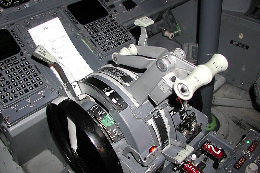
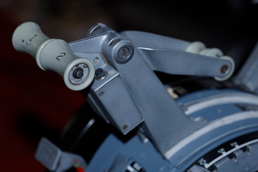
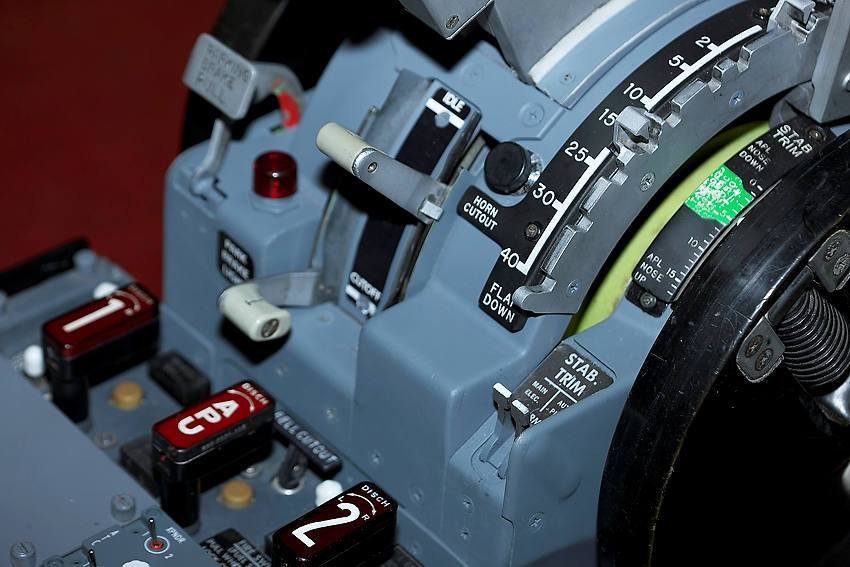
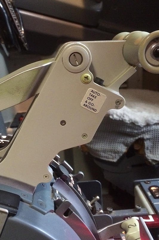
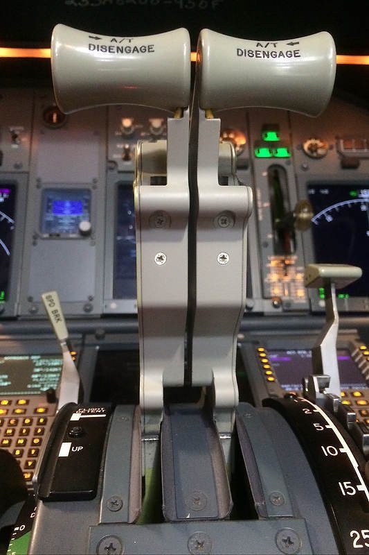
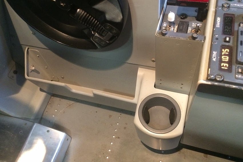
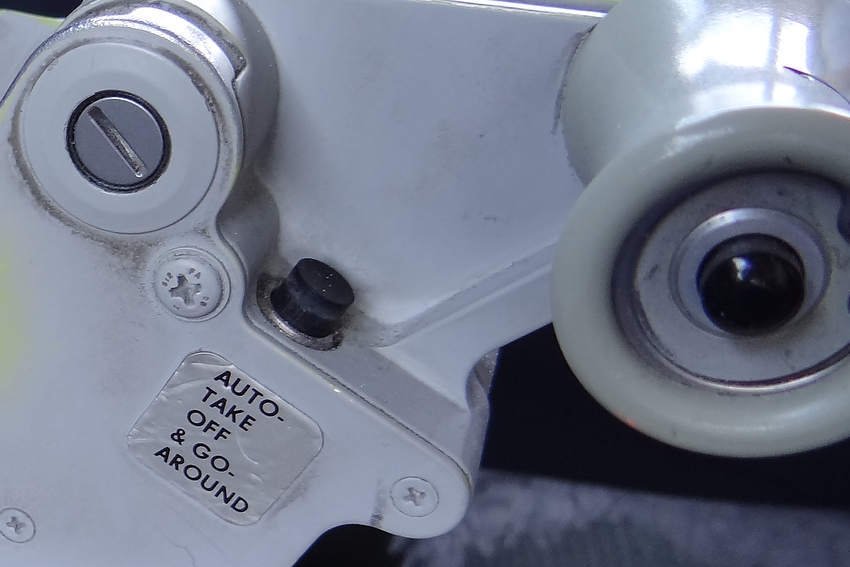
/OEM NG style thrust lever
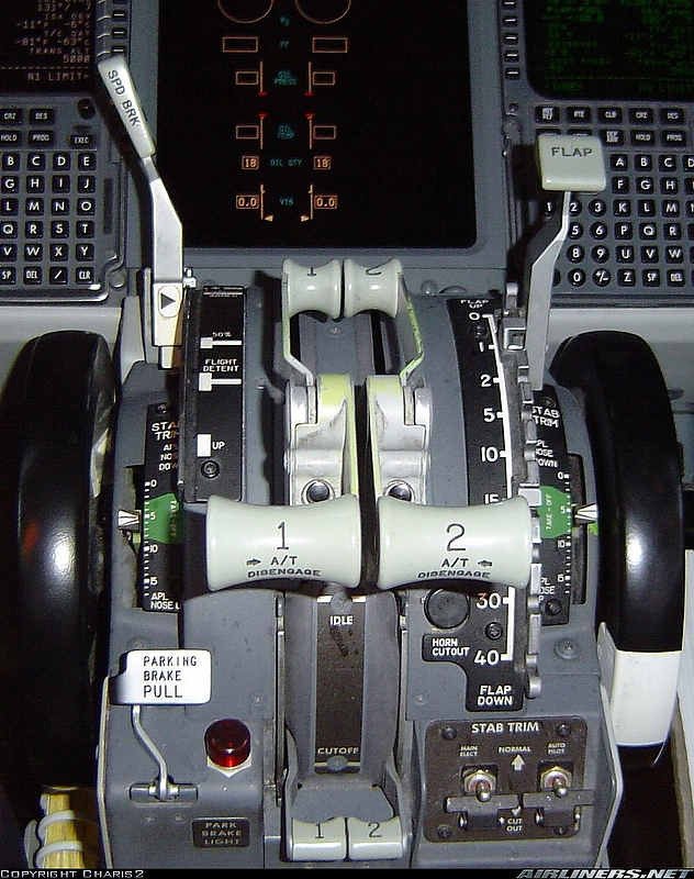
The throttle quadrant for many enthusiasts is the ‘holy grail’ of the simulator, and many individuals strive to ensure that the throttle operates as close as possible to its real world counterpart.
The automated systems in the 737 aircraft drive the movement of the thrust levers in a coordinated manner, and it’s the accuracy, speed, and synchronised movement that enthusiasts try to replicate.
Historical Context
Individuals often use Leo Bodnar Joystick cards, PoKeys, Arduino, and Phidget Advanced Servo cards to interface the throttle quadrant (and other hardware) with some using SIOC (a programming language) to connect propriety throttle quadrants. Calibration, more often than not, was done via FSUIPC, or in a rudimentary way through ProSim737.
Although the throttle quadrant functioned, the position of the levers didn’t match the correct position for the commanded thrust (%N1), and the thrust levers would often be offset against each other and not move in a synchronised manner. These shortcomings lead to the throttle being used only in ‘manual mode’, as the feedback from the software to the throttle didn’t generate consistent and reliable results.
Two innovations have changed this – the introduction of Direct Calibration in ProSim-AR, and the development of the Pololu Jrk Interface Card.
In this article, I’ll explain how to the calibrate the thrust levers using Direct Calibration in ProSim737. I’ll also show you how to initially calibrate, and then fine-tune the Pololu Jrk card, to enable seamless integration with ProSim737. Finally, I’ll discuss some advantages that using a Pololu card brings.
Important Point:
The calibration settings displayed in the various figures (Figures 1-5) are specific to one simulator. The Pololu card settings in your simulator will be similar, however, some settings will be different because of subtle differences in the hardware being used.
ProSim-AR - Direct Calibration
ProSim-AR enables direct calibration of the various flight controls and surfaces directly within ProSim737. This is in-line with their philosophy of trying to keep everything in-house (homogeneous) within ProSim-AR. This not only enables ProSim-AR to maintain control of how the calibration process occurs, but it also aids in troubleshooting should a problem occur.
Direct Calibration is a step forward in keeping ‘everything under one roof’ as opposed to using FSUIPC or another programming language to connect aircraft-related assignments. At the time of writing, it is possible to use direct calibration for the: throttle levers, flaps lever, tiller, speedbrake, aileron, elevator, and rudder.
On a side note, Direct Calibration is one of the strengths of ProSim-AR, in addition to built-in native support (via their SDK and generic driver) for various interface cards (which includes the Pololu card).
Pololu JrK Interface card
Pololu Jrk Interface Card
The Pololu Jrk Interface card is a powerful and highly configurable 12v12 brushed DC motor controller, that provides a stable and robust solution to interface the automated movement of the thrust levers in a simulator environment. Not only are the cards small, but they have been trialled extensively in robotic assignments; NASA uses an upmarket version of the Pololu JrK card to control aspects of the Mars Lander.
The card comes packed with a number of advanced features that enable you to tweak the interaction of the card with ProSim737 which, when combined with a quality 12 volt DC motor and string potentiometer will guarantee higher accuracy and better performance than when other calibration methods are used.
Using ProSim737 and a Pololu Jrk Card to Calibrate Thrusts Levers 1 and 2
The engineering required to enable movement of the thrust levers is comparatively simple.
Each thrust lever is connected with a string potentiometer that in turn connects with a Pololu JrK card. The Pololu card then connects directly to the computer by a USB connection. This creates a closed loop system in which the Pololu card reads the movement of the potentiometers and sends this information to ProSim737 and then to flight simulator.
Obviously, two Pololu cards and two potentiometers are needed; one for each thrust lever, and the calibration of each thrust lever must be carefully done to enable both levers to move together in unison. Additionally, two 12 volt DC motors are needed to provide the power to move the thrust levers.
To connect and calibrate a Pololu JrK card requires three steps (in sequential order):
(i) Download and install the Pololu software;
(ii) Turn on Pololu support in ProSim737 (Configuration/Drivers);
(iii) Configure the initial settings in the Pololu Configuration Utility (PCU);
(iv) Calibrate the thrust levers in ProSim737 (Configuration/Levers); and
(v) Fine-tune the calibration in the Pololu JrK card using the Pololu Configuration Utility (PCU).
Once Pololu support has been selected in ProSim737, the Pololu card will be read automatically by ProSim-AR, and the calibrated settings sent to flight simulator.
Important Point:
Initial configuration in the Pololu card (iii) must be done prior to calibrating the thrust levers in ProSim737 (iv).
Subtle Differences (Hardware)
Every throttle quadrant is different as we use different hardware, potentiometers, and DC motors. It’s important to understand that, subtle differences in the hardware used in the throttle quadrant, will affect which settings are used to configure the Pololu card.
The following may have a direct effect on the accuracy, speed, synchronisation, and movement of the thrust levers.
(i) Type of 12 Volt DC motor used;
(ii) Variable output between DC motors;
(iii) Type of potentiometer and the manufacturing variance (+/-) between units;
(iv) The friction generated by each of the thrust levers; and,
(v) The manufacturing variance (+/-)between each of the Pololu cards.
The type of potentiometer used will make a difference to how accurately the Pololu card can read the movement of the thrust levers. If an inexpensive linear potentiometer is used, then the accuracy will continually degrade as the carbon trail on the potentiometer is slowly destroyed. This will lead to frequent recalibration and fine-tuning of the settings. Using a string potentiometer will resolve this issue as contamination leading to loss in calibration is minimal. Use of a Hall sensor will deliver an even greater degree of accuracy (as these sensors are extremely accurate), although it’s debateable to exactly how much more accuracy will be achieved in the movement of the thrust levers, and whether this will be noticed.
High-end string potentiometers and Hall sensors are often used in the medical industry where the tiniest input movement needs to be accurately measured. In comparison, the movement of the thrust levers (input) is quite rough.
Performance can also be affected by the type of 12 volt DC Motor used. If the motor has an amperage either too high or low, or the incorrect gear ratio, the thrust levers may be over or under powered, and no matter what finesse in calibration, the results will be less than optimal. If a low end motor or a hobbyist servo is used, the resolution of the motor steps will not be good enough to deliver a smooth transition when the thrust levers move; the levers will stagger as %N1 changes.
Also, depending on the type of throttle you’re using, the friction caused by the thrust levers moving will also be different; some levers move relatively easily while others require additional torque from the DC motor to move.
Interestingly, if you’re using an OEM throttle, there may also be differences between throttle unit builds, as each throttle quadrant is manufactured to be within a range of specific tolerances (manufacturing variance). For example, the friction needed to be overcome to move the thrust levers is often different between throttle quadrants, and even respective levers on the same quadrant.
RAW data from thrust lever 1 during automated flight. The upward and downward spikes signify major departure from acceptable operation. The red line demonstrates how the spikes can be flattened when a Pololu card is used
Calibration of the thrust levers in ProSim737 without using a Pololu card does a reasonable job, however, the output is often quite rough – think of a graph with lots of upward and downward spikes.
For consistent smooth operation the spikes shown in Figure 6 must be smoothed down. A Pololu card enables fine-tuning of this output to achieve a consistent and repeatable output
Installing the Pololu JrK Card Software and Initial Configuration
Although ProSim-AR will automatically read the Pololu card, you’ll still need to install the Pololu software to enable access to the Pololu Configuration Utility (PCU).
Two Pololu JrK cards installed to Throttle Interface Module (TIM). The compact size of the cards is readily apparent. These cards deliver a big ‘punch’ for such a small size
After downloading the software from Pololu, open the ZIP archive and run ‘Setup.exe’. If the installer fails, you may have to extract all the files to a temporary directory, right click ‘Setup.exe’, and select ‘Run As Administrator’.
The installer will guide you through the steps required to install the Pololu Jrk Configuration Utility, the JrK Command-line Utility (JrkCmd), and the JrK drivers on your computer.
Once the software has been installed, there should be an entry for the JrK in the ‘Pololu USB Devices’ category of the Device Manager. This represents the card’s native USB interface, and it is used by the configuration software.
The software can be downloaded directly from the Pololu website.
To read the Polulu user guide: Pololu JrK User Guide.
Recommendation:
Create a shortcut to the Pololu Configuration Utility (PCU) and save this shortcut to your desktop or menu system. This will enable quicker and easier access to the utility.
Limitation
For brevity and simplicity, I haven’t discussed every configuration setting in the PCU. Instead, I’ve included several screen captures (Figures 1-5) that show the various configuration settings for reference. These settings should provide a benchmark to enable you to configure the card.
Notwithstanding this, I have enlarged on the two most important settings in the PCU that have a direct influence on the accuracy, and synchronised movement of the thrust levers.
Confirming the Pololu Card Connection
After the initial configuration settings in the Pololu card have been configured, it’s a good idea to test the card’s functionality to confirm connection with ProSim737. This is done by opening the Pololu Configuration Utility (PCU) and setting a manual target speed (Figure 1). To engage the target speed, select ‘Apply’.
Pressing ‘Apply’ will command the card to determine the position of the thrust lever as indicated by the potentiometer. If the thrust lever is not at the same position on the throttle arc as indicated by the settings in the PCU (and it probably won’t be), the thrust lever will move to the commanded position. If this movement occurs, it’s a good sign that everything is functioning correctly.
Calibrating Thrust Levers in ProSim737
Assuming everything is working, the next step is to calibrate the thrust levers in ProSim737.
Calibrating the movement of the thrust levers is comparatively straightforward. Each thrust lever must be calibrated independently of each other, otherwise both levers will not move in unison when the automation (aircraft autopilot) is selected.
(i) Enable Pololu support in Configuration/Drivers tab in the ProSim737 User Interface;
(ii) Open the Configuration/Levers tab and assign for each throttle lever the Pololu input and output;
(iii) Select the appropriate Pololu card for the analogue input and select ‘Feedback input’(1);
(iv) Select the appropriate Pololu card for server output and then select ‘Motor output’(1); and,
(v) Move the virtual sliding tab with the mouse (you should see the respective thrust lever moving).
(1) Located in adjacent drop down box.
To calibrate each thrust lever the virtual sliding bar is moved with the mouse device. To register the position the ‘Min’ and ‘Max’ is selected.
Slide the bar until the physical thrust lever rests in the idle position (the physical thrust lever should move as you slide the bar). When the thrust lever is in the idle position select ‘Set Min’. Next, move the virtual sliding bar until the position of the physical throttle lever rests in the fully forward position. When it does select ‘Set Max’.
For calibration to occur, the minimum and maximum positions must be registered. This process must be completed for both thrust levers.
Important Points:
On some set-ups the ProSim737 software reads the throttle movements backwards. In other words the position of the thrust lever will move in the wrong direction. If this occurs, reverse the order - press ‘Set Max’ instead of ‘Set Min’ and ‘Set Min’ instead of ‘Set Max’.
Calibration occurs when the virtual sliding bar is moved with the mouse device. Calibration is NOT done by physically moving the thrust levers.
To improve accuracy, select ‘Min’ and ‘Max’ only when the physical thrust lever has reached the end of its movement cycle. This task may need to be done a few times to ensure the most accurate position is registered by the calibration process.
Ensure the option ‘closed loop autothrottle’ is NOT selected within the ProSim737 MCP software (right click the virtual MCP to open the MCP Config menu.
It’s recommended to use string potentiometers or Hall sensors to register the incremental movements of the thrust levers. These will provide a greater degree of accuracy.
Always calibrate the thrust levers in ProSim737 prior to fine-tuning the Motor and PID in the PCU Interface.
It’s at the discretion of the user to calibrate and fine-tune the Pololu card to a level of accuracy they believe is a reasonable compromise between the position of the thrust levers on the throttle arc, and the speed at which the thrust levers move.
Fine-tuning Using The Pololu Configuration Utility (PCU) Tabs
To fine-tune the outputs from the throttle quadrant, the PCU must be opened. The two tabs that are used to determine the accuracy, position, speed, and synchronisation of the thrust levers are the Motor and PID tabs.
The Motor Tab in the PCU (Figure 4) can be used to alter the current (amperage) and the duty cycle. Both settings affect the output of the motor (which in turn alters the speed that the thrust levers move).
If the motor has an amperage either too high or low, then the speed that the thrust levers move at, may either be too slow or too fast. Furthermore, DC motors often exhibit manufacturing variances (+/-)and it’s common to have 2 identical motors with slightly differing output.
If the output is not equalised between the two motors, the position of the thrust levers will be staggered and synchronisation between each of the levers won’t be possible. Likewise, a different power output may be required to overcome the internal friction of the thrust lever, to enable movement of the lever to occur, .
Tweaking the motor duty cycle will help eliminate these differences enabling synchronisation of the thrust levers.
The PID Tab in the PCU (Figure 3), an acronym for proportional coefficient, enables in-depth fine- tuning to be applied to the already completed calibration done in ProSim737.
Depending on the power (torque) of the DC motor and the hardware used in the throttle quadrant, the thrust levers may jitter (backward and forward movement when a constant %N1 is set). To eliminate jitter, the PID is fine-tuned until a happy medium is discovered.
Consistency and Reliability
For the most part, Pololu Jrk cards are manufactured to a high quality and are very reliable; you shouldn’t experience a problem with a card. Even so, there may be manufacturing variance (+/-)between respective cards. However, because of the nature of the card, any subtle differences in output can easily be controlled through fine-tuning.
The above said, the calibration of the thrust levers includes many variables that are interrelated, and to achieve consistent results, the components that provide information to the card, in particular the potentiometers and DC motors, must be of the highest quality.
Important Point:
If something doesn’t work as expected, try again using different variables.
Advantages Using a Pololu JrK Card
The benefits of using Pololu Jrk cards cannot be underestimated.
(i) Direct support (reading of card) by ProSim-AR;
(ii) Small size enabling mounting almost anywhere; and,
(iii) Fine-tuning and increased accuracy through use of the PSU User Interface.
Will I Notice A Difference Using a Pololu JrK Card
The question frequently asked is: ‘will I see a difference if a Pololu card is used’ The answer is not straightforward, as there are several interrelated variables (already discussed). If the calibration is done carefully in ProSim737 and the variables tweaked in the Pololu PCU, there is no reason why there shouldn’t be a marked improvement.
Addendum
There has been considerable confusion concerning using the Polulu JrK card with ProSim737. Specifically, whether the potentiometers can be connected directly to the Polulu card, whether dual potentiometers are required, and whether a joystick card, such as Leo Bodnar BU0863 A/X joystick card is required to calibrate the thrust levers.
The ProSim737 software has the ability to read the Polulu card directly. Therefore, the potentiometers can be connected directly to the Polulu card. Because direct connection is possible, a duel potentiometer is not required. The calibration of the thrust levers can be done directly in ProSim737. A joystick card is not needed.
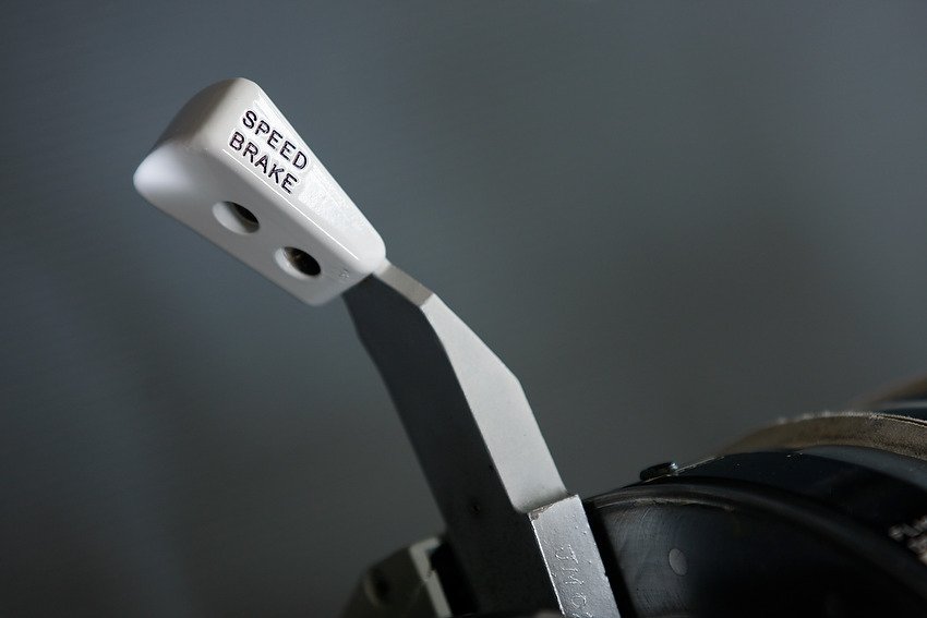
This said, the throttle quadrant in my simulator uses dual potentiometers that connect directly to the Polulu JrK card (to provide feedback) and to a Leo Bodnar BU0836A card (for calibration). The later also being used to register and calibrate the throttle buttons, flaps and speedbrake lever.
Advantage of this methodology, although it does appear slightly convoluted, is three-fold:
The calibration of the thrust levers and feedback can be separated. This can aid in troubleshooting if a problem occurs;
The calibration of the thrust levers can be done outside of ProSim737 using FSUIPC, flight simulator or some other software (if required);
The thrust levers can be used in manual mode without feedback connected. This is because the calibration has been done using a joystick card; and,
By using duel potentiometers and a joystick card you have the option of using other avionics software. In other words you are restricting yourself to only using ProSim737 because of a specific hardware configuration.
Final Call
Evolution is rarely static.
Direct calibration has enabled greater accuracy in calibrating the various control surfaces within ProSim737 and, in concert with using an advanced card such as the Pololu JrK card, has been a evolutionary step forward. This has lead to greater accuracy in the position of the thrust levers on the throttle arc, and almost perfect synchronisation, when automation is selected.
Further Information
This is but a short introduction to calibrating the throttle quadrant (thrust levers) directly within ProSim737 using the Pololu Jrk interface card. For further information concerning the Polulu Jrk card and it’s use with ProSim-TS navigate to the ProSim737 forum and search Polulu. The Polulu website is also worth reading at Pololu.
Acronyms and Glossary
Manufacturing Variance (+/-) – This is where identical items, although appearing exactly the same are very slightly different. Usually the tolerance is so small that it’s indiscernible. However, manufacturing variance in electronics often is the reason why some parts function and some fail soon after first use. An acceptable tolerance will be defined at the point of manufacture. Usually, if an item requires a higher (tighter) tolerance this leads to a higher manufacturing and purchase price. Often, but not always, there is a direct relationship between the price paid for an item and the reliability and longevity of that item.
MCP – Mode Control Panel
PCU – Pololu Configuration Utility
Throttle Arc – The curved piece of aluminium that the thrust levers move within.
Figures 1–5 display the settings for each of the tabs in the Pololu Jrk Configuration Utility (PCU). Note that these settings are generic to all throttles, however, the variables will differ slightly depending upon hardware used.