The backbone of the simulator is the avionics suite, and for the simulator to run effectively this software must be reliable, feature rich, and robust.
There are several avionics suites available to simulate the avionics and functionality of the Boeing 737; Project Magenta, Sim Avionics, and ProSim-AR being the most popular. I have not mentioned Precision Manuals Development Group (PMDG), as PMDG is marketed as a desktop simulation not used widely in a hardwired simulation.
Many virtual flyers assume, that when they purchase an avionics suite, the software will replicate all the aircraft systems, be compatible with their computer and simulator hardware, and probably not need to be updated. Unfortunately, this is rarely the case.
In this article, I will discuss the following (in this order):
The ProSim User Interface;
The ProSim Version Manager;
Various troubleshooting protocols;
Other potential problems (USB Disconnects, Windows Management Settings, etc);
FSUIPC and Sim Connect;
Installing the Terrain Database;
Installing and updating the Navigational Database;
Installing and updating the Visual Flight Model; and,
Connecting ProSim737 with Active Sky 16.
Version 3 (3.00)
This article was primarily written for Version 2.30. ProSim Version 3.00 introduced several new features to the Version Manager which enhance troubleshooting and backing up specific files. Some of the more important changes have been added into this article.
The Reason and Need for Updates
Technology is rarely static, and developers if they are to encapsulate new technology must provide updates to their products. This evolution can be likened to a game of ‘leap frog’; as something new is released, developers ‘tweak’ their software to take into account new technology while (hopefully) still maintaining compatibility with legacy systems.
Another reason for updates is that there is not an avionics suite that completely encapsulates 100% of all systems (and functionality) used in the B737. A possible close exception is PMDG, but as mentioned earlier, this is a desktop simulation (I am not including Level D/Type 7 simulators).
Each company that produces an avionics suite has a specific method to how its software is installed, maintained, and lastly kept up-to-date with improvements, fixes and software upgrades. For example, Sim Avionics beta test changes and improvements themselves (or to a select group of individuals) and then release a version update. This is in contrast to ProSim-AR, who release a beta for client appraisal. Then, after bugs and shortcomings are rectified, release a final release.
ProSim-AR - frequent updates
The avionics suite developed by ProSim-AR for the Boeing 737 Next Generation is feature rich, easy to install and run, and the software is for the most part very robust. The company ‘appears’ to be committed to ensuring that their software operates across a wide range of computer hardware, and interfaces with as many mainstream hardware components as possible (for example, CP Flight, SimWorld, Open Cockpits, Flight Deck Solutions, etc.). In my opinion, the company is very proactive in interfacing with new technology to gain the maximum benefit that new technology brings, which includes increased market share and profitability (for ProSim-AR).
With this in mind, ProSim-AR release updates to their software on a very frequent basis.
Understanding the Basics of the ProSim737 File Structure
It is important to understand the basics to how the ProSim737 file structure is set out, as this will provide guidance to the best way to install an update, and if a problem occurs, troubleshoot.
The ProSim737 suite contains the following components, located in a folder of the same name (Version 3 uses the name ProSimB738, however, for consistency I have used the former name).
ProSim737 (systems module);
ProSim-CDU;
ProSim Audio;
ProSim Display (primary ;
ProSim MCP (Version 2.30 only);
ProSim Panel; and,
ProSim737 Hardware Connector.
NOTE: In Version 3.00, the ProSim MCP display has been removed. The MCP is now part of the ProSim737 systems module and does not need to be opened separately as it did in Version 2.30.
In this article I frequently use three words: displays, instances and modules. For clarity a:
Display refers to anything that is displayed on the monitor. For example, the primary flight display, navigation display, EICAS);
An instance refers to another instance of a display. For example, two instances of the primary flight display need to be opened (opne for the captain and the other for the First Officer); and,
A module refers to a component such as ProSim Audio, CDU, or the ProSim737 systems module).
The folders can be installed to either a server (the computer that has flight simulator installed) or any number of clients (computers networked to the server computer). Duplicate instances of the same ProSim display with the exception of the ProSim737 systems module and MCP display, can also be installed.
When installing duplicate displays (also referred to as instances) of the same name (for example Captain and First Officer CDU or ProSim Display) to the same computer, do not rename the .exe file. Rather, create a shortcut to the .exe file and rename the shortcut to a specific name (for example, CDU Capt and CDU F/O).
The ProSim737 folder and MCP folder (Version 2.30 only) must be installed to the server computer for optimal performance. The other folders can be installed to the server or client computer, either as single or duplicate instances.
The ProSim737 folder contains the ProSim737 systems module. This module interfaces with the other ProSim737 displays and modules.
The folders can be installed anywhere on the computer, however, it’s not recommended to place them in the same folder (ROOT folder) where flight simulator is installed.
Important ProSim737 Files
Each ProSim737 folder contains a configuration (config) file. The configuration file contains information pertaining to screen position, functionality, IP address, etc. The most important configuration file is located in the ProSim737 systems folder. This file, amongst the things, holds the information that relates to specific hardware, functionality and button assignments. All configuration files are named config.xml.
Important file, located in the ProSim737 systems folder are the:
Companyroutes.xml;
Config.xml;
ConfigMCP.xml (Version 2.30 only);
TransitionAltitudes.xml; and the,
Cockpitsetup.xml.
The configuration files are important. These files should be regularly backed up.
Other files that relate to the update process are the updatelog.txt and changelog.txt. The updatelog.txt contains information concerning to the latest update, while the changelog.txt provides a list of changes that has occurred in the various ProSim737 releases.
Important Points:
The most important configuration file is the config.xml file located in the ProSim737 systems folder. This file contains all information that relates to configuration, customization, and hardware. It should be regularly backed up.
Where to Install ProSim737 Files
For ProSim737 to function correctly several folders and their files need to be installed.
ProSim737 systems module: This folder contains the necessary files to run ProSim737. They can be installed anywhere on your computer. A shortcut made to the .exe file (if required).
ProSim737 instances and ProSim737 IOS: These folders include the various displays (PFD, ND, EICAS, etc), the clock, CDU and audio program. The folder can be installed to the server (PC running ProSim737) or to a client computer. A shortcut can be made to the .exe file (if required).
Visual Flight Model (VFM): The VFM (named prosim-B738-v2024) is installed to the community folder in MSFS-2020. Note that the file name for the VFM may change from time to time. The VFM is installed into the community folder (MSFS-2020).
ProSim Module: The module contains information to enable the external surfaces of the flight model to be animated. The module is installed into the community folder (MSFS-2020). Do not to be confuse this file with the ProSim737 systems module.
.lua files: Lua.files are used from time to time to display special effects. Any number of .lua files may be used. These files reside in the FSUIPC 7 folder. The files can also be placed on the client, however, Wide FS will need to be used and set-up correctly.
GSX files: GSX or GSX Pro is a commercial program that operates ground services. For GSX Pro to function correctly with the Visual Flight Model the gsx.cfs file may need to be edited. The gsx.cfs file is located in the documents folder. This folder is found in the Visual Flight Model (prosim-B738-v2024).
ProSim Licence: The license information is manually copied to the ProSim User Interface and the generated license files are stored in the ProSim folder as a .lic file. These files are located: Local Drive (C):\ProgramData\ProSim-AR\ProSimB738.
Ivar modules: Ivar modules (for example, FSUIPC.WASM) are part of FSUIPC and can be found in the FSUIPC 7 folder. The FSUIPC.WASM files should be copied into the community folder (MSFS-2020).
User Interface and Version Manager
The User Interface enables you to customise the avionics suite, configure hardware components, update, and troubleshoot problems.
The interface is straightforward to use and I urge you to become familiar with its tab / page layout and content. I will discuss some of the troubleshooting features of the interface later in this article.
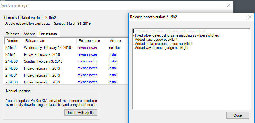
Included in the interface is a Version Manager that can be used to update the avionics suite. When connected to the Internet, the Version Manager compares the release date of the currently installed avionics suite to the latest available release.
The Version Manager enables the avionics suite to be updated from within ProSim737. It's accessible from the User Interface (help/updates).
The Version Manager has three tabs: Releases, Add-ons and Pre-releases.
Releases tab will display a list of final ProSim737 releases (along with release information and the date it was available). To install the latest release, or to roll back to an earlier release, you select the install link in the Actions title. This will cause the selected release to download and be installed to your computer copying over (and updating) a previous release installed.
Add-ons tab displays various add-ons that ProSim-AR have made available. An example being the ProSim737 aircraft flight model.
Pre-release tab will display a list of beta releases. Operation is identical to the releases tab discussed above.
One of the advantages of the Version Manager is that it enables you to quickly update the avionics suite to a beta pre-release, final release, or roll backwards to an earlier release. It also provides information concerning the beta release (Release Notes tab), in addition to enabling you to monitor respective updates to the 737-flight model (Add-ons tab).
Three methods can be used to update the ProSim737 avionics suite:
Download the latest release from the ProSim-AR website (standalone requiring installation);
Download the latest release from the Version Manager (zip file); or
Download and install from the Version Manager a beta pre-release or final release.
There is no preferred method, however, option (iii) is the easiest way.
Version 3.00 Improvements to the Version Manager
In Version 3.00 additional improvements have been made to the Version Manager to aid in troubleshooting and the backing up of important files.
Opening the ProSim737 systems user interface, select Options (located beneath Connected Hardware) will open a Configuration File Manager & Mapping page. This page displays the hardware family, type and mapping and whether the hardware is in use or not by ProSim (denoted by the colour).
Highlighting an item (text will change to red) and clicking the mappings section will open an additional table that displays a description of each function and its output port number for that particular interface card. If you click the mappings table number a page opens displaying what function that card is connected.
Finally, at the bottom of the table are two tabs that enable you to create or restore a backup of the config.xml file (discussed in detail later on).
A backup of the file is saved to C:\Program Data\ProSim-AR\ProSimB738\Backup\. The config.xml backup is date named enabling consecutive backups of this file to be made and saved.
Beta Pre-release or Final Release ?
ProSim-AR regularly adds functionality and improvements to their avionics suite via beta pre-releases. A beta pre-release enables users to test their hardware set-up with a release prior to it being finalised. As such, beta pre-releases often have bugs, shortfalls and other problems associated with them.
ProSim-AR have a dedicated web-based forum, and request that beta users provide feedback on a pre-release. This enables issues to be rectified prior to making available a final release via the Version Manager.
The Updating Process
The ProSim737 Version Manager (if used) is smart enough to replace all files within the ProSim737 folder system, with the exception of configuration files and any file ending in .xml (these files are kept intact).
However, if a release is downloaded from the ProSim-AR website, or the ZIP file option is used, then it will be necessary to manually insert the configuration files to their respective folders.
ProSim737 updates in sequence. This means, that after the updated software has been downloaded and installed, the ProSim737 systems module will open. Then as each ProSim737 display or instance is opened by clicking the .exe file, that display or instance will update.
A pop-up box will display 'updating configuration' as each display or instance updates its content and synchronises with the ProSim737 systems module. When an update to a display or instance has been completed, the software will generate the updatelog.txt file (as discussed earlier).
The time taken to update across a network between server and client computers depends upon your network speed; usually less than 30 seconds.
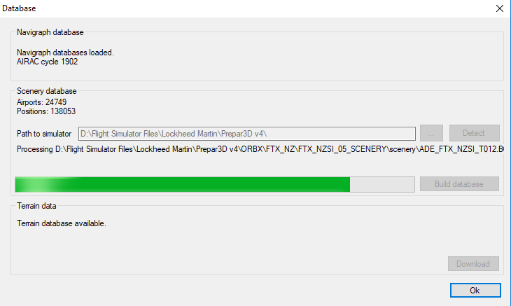
Although theoretically not required, the Scenery Database (config/database) should be checked to ensure it's path is connected to the correct folder in Flight Simulator. It also doesn't hurt to rebuild the database. Rebuilding the Database following an update ensures that the link between the database, ProSim737 and Flight Simulator has not been corrupted.
Important Point:
Customising How ProSim737 Updates
There are three ways that the User Interface can be set-up to update the avionics suite:
Manual updating;
Ask before updating; and,
Automatic updating.
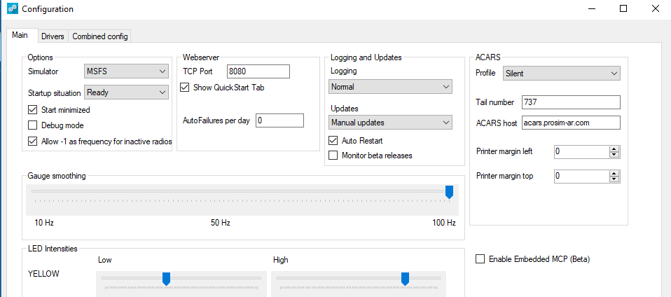
The method is customised in the User Interface, accessible from the drop down box (config/configuration/updates). The interface also has a box that an be checked/ticked if you want the interface to monitor when a beta release becomes available; a screen pop-up will be displayed when you open the avionics suite.
Backups and Install from Backup
I recommend keeping a complete copy of each ProSim737 folder from the server and client computer. By backing up the complete folder, you are also backing up the configuration and other important .xml files.
Theoretically, the Version Manager negates the necessity to maintain a backup of ProSim737 (or the configuration file), as the configuration and other .xml files are maintained intact. However, by keeping a complete copy of the last ‘working’ release, it’s easy to ‘change out’ between releases (roll back or forward).
All you need to do is delete the ProSim737 folders from the computer, and then copy/paste the earlier folders to the same locations. All the files are intact and ProSim737 will load whatever release has been installed.
If you don't want to keep a complete copy of the folders and files, then it's also straightforward to roll back to an earlier release by using the Version Manager. The manager will download the selected release from the ProSim-AR server and install it overwriting the newer release on the computer.
My preference is to keep a complete copy the release and copy/paste if you want to roll back.
Automatic Backup of Config.xml File
The Version Manager has a handy tool automated within the software. It will now examine and compare the config.xml file during the updating process. If the file is different between the two copies, the Version Manager will create a back-up copy called config-old.xml.
The auto backup provides a second level of protection to this important file. it also enables different config files to be saved. Every time a config file is backed up the file is date stamped.
Version 3.00 introduced the ability to easily backup and restore the config file. Open the User Interface and select the small arrow (adjacent to options). This will open a second window that examines what interface cards and hardware ProSim is connected with. At the bottom of the page there is a command that enables you to save the config file or restore a backed up config file. The file is saved within the ProSim file structure or you can select a preferred folder.
Important Points:
Always make a backup up your configuration (config.xml) files. The config.xml file is the most important file in ProSim as it records your configuration and various user selected settings.
If downloading and installing a fresh copy of a release from the ProSim-AR website, then the configuration files will need to be manually added to each folder (from your backed up files).
Updates using the Version Manager replace all files within the ProSim737 folder structure, with the exception of configuration files and any file ending in .xml.
The Version Manager displays the current release of ProSim737 you have installed.
A good idea to backup a copy of all the ProSim737 folders on both server and client computers. Doing so allows you the option to easily replace a ProSim737 release with an earlier release number.
After running any update, the ProSim737 Scenery Database should be rebuilt.
Troubleshooting Updates
This section is not the ‘Holy Grail’ to resolve all problems. Rather, it’s what should be done prior to requesting help from the ProSim-AR Development Group. Some of the methods used to troubleshoot are quite simple, yet effective.
Occasionally there may be a problem with an update. The update may cause one of the displays .exe files to loop (open/close/open/close), or there may be limited functionality, or perhaps the ProSim737 systems module will continually crash.
Recommended Initial Troubleshooting Protocols
Before spending valuable time in advanced troubleshooting, I suggest you check/do the following:
Shutdown all computers and restart;
Ensure that all displays and instances within all folders on the server and client computers have been updated to the new release (check the update file in the folder or check the release version number by right clicking the screen display and selecting configuration);
Close and re-open ProSim737 systems module and all displays on the server and client computers;
Check to ensure that the correct IP address is recorded for each display window opened. To check this, right click the opened screen and select configuration. This will open the screen’s user interface. Check that the correct IP address recorded in the server box;
Check the version of .Net Framework on your client and server computer (discussed later);
Replace the configuration file (config.xml) in the ProSim737 folder with a copy of your backup configuration file;
Delete all ProSim737 folders from your server and client computers and download/install from the ProSim-AR website a fresh copy of ProSim737 (remember to replace the configuration files in the ProSim737 folders to maintain your functionality settings and screen position); and,
Open the User Interface (config/configuration) and confirm that the correct simulator and connection method (FSUIPC, Sim Connect, MSFS) is listed in the options box. Also ensure the enable embedded MCP beta is not selected, all installed I/O modules and software are operational, and the simulator is connected. Furthermore, check that all appropriate drivers have been selected for the add-on components and software you are using (config/configuration/drivers).
Usually problems are resolved by restarting your computer, reinstalling the config.xml file, or reinstalling ProSim737 from a fresh download.
On rare occasions, the configuration file in the ProSim737 systems module may have become corrupted during the update process (jumbled and altered assignments). If you suspect a problem with the config.xml file, delete the current file and copy/paste your backup configuration file to the folder.
Often, the easiest and fastest method to alleviate issues and save considerable time is to DELETE all instances of ProSim737 from the server and client computers and reinstall ProSim737. Before doing this make sure you have a backup of any files you may wish to keep (configuration files, etc.).
Download the latest release of ProSim737 from the ProSim-AR website. Copy the folders to the same location and add a copy of the respective configuration file to each folder. Then, download the beta release (if required).
A quick word when trying to detect where a problem may be occurring. Always test with a minimal or vanilla setup. By this I mean deactivate on-line weather and winds and do not connect any add-ons other than those installed into the flight simulator platform (Prepar3D, etc). Test with a minimal setup; if everything is OK, then add the next program and so forth.
Advanced Troubleshooting, Log Files and the Input Debugger
If the above-mentioned ideas have failed, or the problem relates to a switch, toggle or USB disconnection of hardware, then the next option is to use some of the features available in the User Interface. Namely the: System tabs, Driver tab, Input Debugger, Logging features, and Debug Mode. (config/configuration/main tab/drivers tab). Let's look at each in turn.
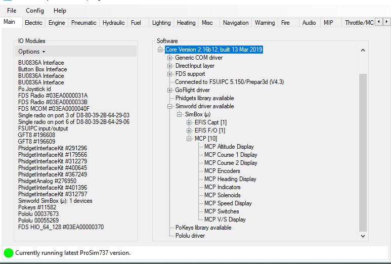
Main Tab
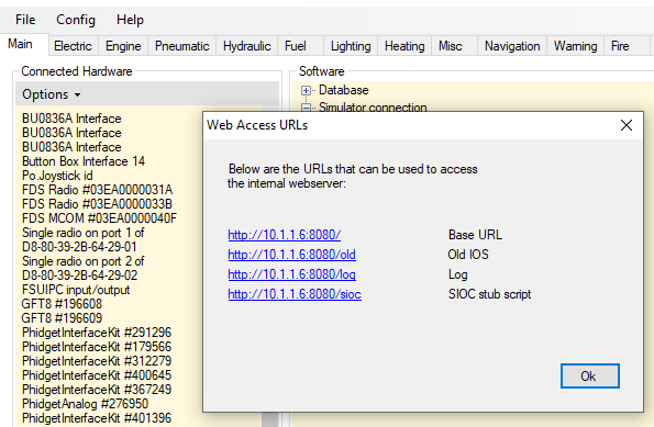
After opening the User Interface, the first tab that is usually seen is the Main tab. The Main tab displays a list of registered and connected interface cards. It also displays the add-on software components that are specific to your simulator configuration. This screen is ‘live’ meaning that as you add or remove a device or interface card from the computer the connection (and list) will be updated.
The main tab is particularly helpful in identifying hardware USB disconnects (Windows USB disconnect ding-dong sound).
In the case of USB disconnects, note any interface cards that you have connected that are either not displayed in the list, or flash on and off simultaneously with the ‘ding-dong’ sound; this will most likely be the offending card/device. Often removing and replacing the USB connection will resolve a problem.
If the problem is a connection or functionality problem that relates to an add-on component (for example SimWorld MCP, CP Flight, Flight Deck Solutions, etc.). Click the + symbol adjacent to the name of the device in the software list. This will expand the selected folder for the item in question. Components not operating correctly, or not connected will be highlighted in red.
Enlarging on the above. if you select option under I/O modules (located in the ProSim737 systems user interface) you are presented with 'store currentlist a srequired'. This is a very handy feature in that it saves, as a profile, the interface cards used. If at anytime the cards connected to ProSim737 do not match this list, the disconnected card/hardware will be displayed in red.
Important Point:
The list displayed in the Main tab includes all legacy components (for example, interface cards that previously may have been used but are now not connected). To reflect the most up-to-date items, the configuration file in ProSim737 systems folder must be edited. This post in the ProSim-AR forum explains how to remove these entries: Removing Old Entries in Config File.
Drivers Tab
One of the advantages in using ProSim-AR, is that the developer has pre-installed and checked the connectivity of drivers for several add-on hardware components. This removes the need to regularly update drivers.
The Drivers tab displays a list of all drivers that can be used with ProSim737. For an add-on component to function, the driver specific to that component must be selected (checked/ticked/turned on). If it isn't then the component will fail.
If you have updated ProSim737 to a newer release, and have not used the Version Manager (manual update from the website), then there is a possibility that the correct drivers for your components have not been selected.
Functionality - Checking Inputs and Outputs (System Tabs and Input Debugger)
There are two ways that the User Interface can be used to check whether the movement of a component (input/output) is being registered by ProSim737 and operating correctly: the System tabs and the Input Debugger.
System Tabs
The System tabs correlate to various aircraft and simulator systems, and when opened will display a list detailing the functionality for that particular aircraft system.
If the switch, toggle or whatever component in question is manipulated, there will be a corresponding indication shown in the Systems tab for that component.
I'm unsure if the System tabs were designed with problem troubleshooting in mind. Nevertheless, the various tabs can provide useful and helpful information and should form part of your troubleshooting system.
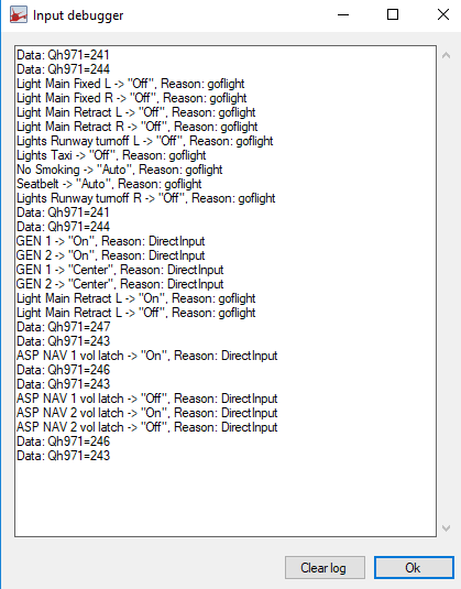
Input Debugger
The Input Debugger (help/input debugger) is very easy to use, and the information it generates in its text box may help determine where a problem may reside.
The first time the Input Debugger is selected, a display window (debugger window) will open showing dozens of entries; the list can be confusing to read. It's recommended to clear the list to make the debugger easier to use (press the clear list tab).
With the Input Debugger open, you physically move the component in question (switch, toggle, lever, etc). As soon as you move the component, you will note that its input, output and other related information is displayed in the debugger window.
The use of the Systems tab and Input Debugger is an ideal way to check that ProSim737 has registered the movement (input/output) of a component.
There is also a MCP debug option located in the config file of the MCP display (Version 2.30). Opening the debug option in the MCP only displays information concerning the MCP.
Debug Mode
The debug mode is an advanced option that should only be used when requested by the Development Group (config\configuration\main-debug mode). Some explanation of the mode is needed.
ProSim737 will only generate a crashlog.txt that relates to problems within its own software; it will not generate a crashlog.txt file if the problem is located outside of its software. In such circumstances, the debug mode can be used to force ProSim737 to generate a crashlog.txt file. This may aid in troubleshooting.
The debug mode will generate a large volume of entries, which to anyone but a software developer will be nonsensical. The generated files should be sent to the Development Group.
A further debug mode is located in the MCP tab (config/configuration/main/MCP). As the name suggests this debugging tool should only be used when there are problems occurring with the MCP.
Important Points:
If the problem you are experiencing does NOT generating a crashlog.txt file (after deleting the file), then the problem is NOT related to the ProSim737 software, but rather to an outside source.
The debug mode should ONLY be used to generate the crashlog.txt file, after which it should be turned off. Furthermore, it should only be used if requested by the Development Group.
Log Files
ProSim737 generates a number of log and crashlog files that can be examined to determine problems.
The two primary files, which are located in the ProSim systems module folder are the log-System.txt and crashlog.txt files.
Further log files (log-Display.txt, crashlog,txt, log-Audio.txt, etc) can be found in the various ProSim displays (for example, display folders, CDU folder and audio folder). Secondary log files can also be generated for LNAV and VNAV using HTP protocols. Scrutinizing these files can often provide incite to the cause of a problem.
The log files, with time can become quite voluminous. This is because additional information is added to the log every time ProSim737 is opened. Often it’s easier to view a file that displays information that relates to the last simulation session.
Therefore, when trying to troubleshoot an issue, it's a good idea to delete the log-System.txt and crashlog.txt files; the software will automatically generate both files from scratch when ProSim737 is re-run, and the resultant entries will only record the data from the last simulator session - this makes for easier reading.
Sometimes more detail is required in a log file. To select more detailed (aka verbose) logging, open the User Interface (config/configuration/main/logging). In the Main tab, beneath Logging and Updates, there is a drop down box - select either normal or verbose logging.
It’s recommended, when using the simulator, to leave logging set to normal (unless testing). The reason for this is because the verbose option will generate a significant increase in the number of entries to the various logs with a subsequent increase in system resources.
If a crash log file is not generated for some reason, navigate to the Windows Event Viewer. The Event Viewer may provide further information (Google Event Viewer if you are unsure what this is).
In addition to the primary log files, secondary log files can be used to harvest information pertinent to a specific system; for example, VNAV and LNAV. These files should only be enlisted when requested from the Development Group.
LNAV log files can be viewed by opening your web browser and selecting 127.0.0.1:8080/lnav or vnav (you replace the address with your own address).
An additional log, that more or less duplicates the information found in the system-log.txt file can be viewed by accessing the web-based URL (help/web access URL's) - http//10.1.1.6 8080/log. A shortcut to this can be found under the help tab in the ProSim 737 User Interface window. Web-based URL's were used in earlier versions of ProSim
Important Points:
ProSim737 will generate a new log-System.txt and crashlog.txt file if either of the files are deleted.
Whenever posting to the ProSim-AR forum a question concerning a problem, its a very good idea to attach the log-System.txt and crashlog.txt files to the thread. These files can then be perused by the Development Group.
Other Potential Causes of Problems
The list could be infinite! However, the following 'potential culprits' seem to regularly cause problems for some users.
Opening Sequence of ProSim737 Displays and Flight Simulator
Sometimes following an update, ProSim737 will crash (drop-out). If this should occur, there may be an issue with the sequence that the various programs are opened (run).
Theoretically, all the ProSim737 displays should connect automatically with the ProSim737 systems module is opened - no matter what the sequence. This said, changing the sequence that the ProSim737 is opened can often resolve problems.
Some users have reported that opening the flight simulator program before ProSim737 resolves drop-out issues, while others suggest the opposite. Similarly, some users recommend opening the ProSim737 systems module before launching the other ProSim737 displays.
Whatever the sequence, changing the sequence that programs are opened should form part of your initial troubleshooting regime.
Recommendation
I recommend opening the programs in the following order:
Run the flight simulator program and allow the aircraft to sit on the runway.
Run weather programs, AI or other ancillary programs.
Run the ProSim737 systems module and allow it to connect.
Run ProSim737 instances such as displays, CDU, audio and clock
Run ProSim IOS (instructor operating station).
An easy way to do this is to create a batch file to run programs sequentially with a pause between run times.
Important Point:
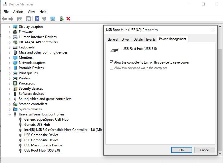
Windows Power Management Settings
If a USB device disconnect occurs after a period of elapsed time, then the computer’s Power Management Settings should be checked.
The Power Management Settings enable the computer to turn off a device to save power; this is done following a period of elapsed time, or after a device has not been used for some time (for example, USB devices and display monitors).
Earlier operating systems maintained the settings established in Power Management, however, Windows 10 has a nasty habit of changing the Power Management settings without warning. Therefore, the first check should be the device manager to check that the settings are as they should be.
In the Device Manager dialog box, expand the Universal Serial Bus controllers tab, right-click each USB Root Hub, and click Properties. In the USB Root Hub Properties dialog box, click the Power Management tab. The setting that allows the computer to turn off the device must be turned OFF (do not tick/check).
Additionally, check the Power and Sleep options. Depending on the operating system used, there may also be other tabs associated with power options. Search Advanced Power Settings/USB/ and suspend/disable power management or sleep function.
USB Disconnects and Other Hardware Issues
The list is almost infinite. However, for those using a number of interface cards and relays, a potential problem can be located with the USB cable, cleanliness and tightness of USB connections (including any USB hub), and loose wiring (especially if connectors have been used).
Clean the USB connections with a quality cleaner to ensure cleanliness and make sure the USB connectors are tight. If the connectors need tightening, this can easily be done by pushing the small tabs inward on the female USB connection.
Surprisingly, wires that have been connected to relays by connectors can also work their way loose either from the connector blade on the relay or from the connector themselves. This is caused by the continually opening and closing of the connected relays (movement and vibration), and by the continual heating and cooling of the wires (which can loosen wires from the connector).
FSUIPC and Sim Connect
ProSim737 can be connected with flight simulator either by FSUIPC or Sim Connect. However, it should be noted that from Version 3.24, FSUIPC is no longer supported. It is recommended that Sim Connect is used. Prior to release 3.24, FSUIPC can be used, however, ProSim-AR offer little support for FSUIPC problems.
Important Point:
Terrain Database (DEM) Installation
The Terrain Database is a separate folder downloaded from the ProSim-AR website. The data when downloaded is in a zip file which when uncompressed should install the terrain data to a folder called DEM located at: C:/Program Data/ProSim-AR/.
Sometimes the installer doesn't function correctly. If this happens, uncompress the files to your computer's desktop (or wherever) and copy the folder called DEM (and its files) to the location above. When done correctly you should have folder called DEM in C:/Program Data/Prosim-AR/DEM.
Once the files are installed, run the ProSim737 systems module (.exe file) and enter the menu at the top of the User Interface. Select CONFIG and rebuild the database. The User Interface should have displayed 'Terrain Database Available'.
The information from the terrain database is recorded in the logdbbuild.txt file located in the ProSim737 systems module folder.
Navigraph Data Installation
Navigraph is the navigation database used by ProSim737. It is purchased separately to ProSim.
The correct navigation database (at time of writing) to download from the Navigraph website is ProSim737 2.24b1 (and above). This number will chnage with time; ensure you download the latest release.
Navigraph have an installer (FMS Data Manager) which a standalone program that is free to use. When setup correctly, the installer will download, un-compress, and install the Navigraph files to the correct folder structure on yuor computer.
Once the database is installed or updated, the ProSim737 systems module (.exe file) must be run, and the database rebuilt (User Interface - select CONFIG and rebuild the database). The database AIRAC cycle number will be displayed in the User Interface.
If the database does not update, there is a possibility that either that downloaded file is corrupt, or more than likely the database has been installed to the incorrect folder structure.
In this case, un-compress the downloaded files to your computer desktop (or anywhere) and copy the database to C:/Program Data/Prosim-AR/Navdata.
Important Point:
.Net Framework
Without going into detail, .Net Framework (pronounced Dot Net) is a language that is designed to bridge other computer languages so that they can be understood. .Net Framework is designed and written by Micro$oft, and ProSim-AR have used it in newer releases of ProSim737.
.Net Framework must be installed to all client and server computers.
Windows 10 Updates
Windows 10 has a feature that automatically updates essential files (as determined by Micro$oft) when the computer is connected to the Internet. Often, the user is unaware that the files have been updated, as the update occurs in the background.
Sometimes a problem will occur when a Windows update deselects features in ProSim737 that are required. For example drivers.
The Windows 10 updating feature can be deactivated if you use Windows 10 Professional, however, it cannot be deactivated in the Home edition (without registry hacking and other work-arounds).
Batch Files and Shortcuts
It’s common for individuals to use a batch file to open ProSim737, or at the very least to use a shortcut to the original .exe file within a specific folder. It’s also commonplace to rename the .exe file to something meaningful other than ProSim Display (of which there are several instances).
DO NOT rename the original .exe file. Rather make a shortcut to the file (right click and make shortcut) and rename this file. If you do rename the original .exe file, the Version Manager will not replace the renamed .exe file and the release update will fail.
Hardware/Mapping
The config.xml file contains the information needed for ProSim to connect with whatever hardware you are using. Often this hardware changes as items become obsolete and are replaced - for example, interface cards may be updated. The Hardware/Mappings section of the config file will not these changes. Rather, it will add new hardware mappings to the list.
To clean up the mappings section, it is necessary to open the config.xml file in a text editor and delete all entries between the <Hardware> section headers. When the ProSim737 systems menu is opened, a new hardware/mappings section will be generated that includes only the current hardware connected.
ProSim737 Visual Flight Model
ProSim737 uses a dedicated flight model.
The flight model has a built in installer which makes the process of installing straightforward - providing you follow the instructions as written by the developer in the opening screen. The flight model is installed either to the Prepar3D folder or to the community folder if using MSFS-2020. If using the later, the flight model can be installed to a generic folder outside of the community folder and then linked to the community folder.
Prior to installing a new flight model, it is recommended to uninstall the earlier flight model. This can be done by using the add/remove program options in Windows or by opening the uninstaller program that comes with the flight model. Whichever option is selected, you must understand that the installation of the newer flight model will replace any existing files that relate to the model.
The files that are affected are those that reside in the aircraft folder. The below folder is the location of the folder in my computer running MSFS-2020. Your location will be different, however, the bolded entry is generic for all users.
D:\\Flight Simulator\MSFS2020Community Folder\Aircraft\prosim-B738-v2023\SimObjects\Airplanes\prosim-b738-2024.
Installation of a new flight model will replace any altered files, additional sound files, and added aircraft liveries with default files. I strongly recommend that you backup the aircraft folder prior to updating the flight model. After the new flight model is installed, you can then change-out any files that you want from the previous model.
Important Point:
Active Sky FS
The weather radar used by ProSim-AR will only function with Active Sky. It will not display a weather radar for any other third party weather or from MSFS-2020, MSFS-2024 or P3d. Installing Active Sky is very straightforward, however, for the Active Sky software to communicate with ProSim requires additional configuration.
Open the ProSim User Interface and select Config/Configuration. The fourth box on the right enables you to enter Active Sky settings so that Active Sky can communicate with ProSim. The following settings are used:
Host or IP - localhost (note lower case and one word).
Port - 19285.
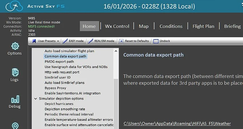
App Data Path - C:/Program Files/user/Roaming/Hi-Fi/AS-FS/Weather.
The box must be ticked (checked) to set Active Sky as the active weather service.
The App Data Path can be checked (and copied to enter into ProSim-AR) by selecting in Active Sky: Options/General Options/Common Data Export Path. Copying this data string will ensure ytou do not make a mistake in syntax (see image in gallery).
Afrer setting the above parameters the ProSim User Interface will be updated with an addition line indicating whether Active Sky is connected or disconnected.
Configuring ProSim Without the Simulator Running
In earlier versions of ProSim737, it was possible to configure switches, audio, and other settings without running the flight simulator. In more recent releases, this is no longer supported, and the simulator must be running for configuration to work correctly.
A practical workaround is to start ProSim737 in FSUIPC mode instead of SimConnect mode. Using FSUIPC mode allows you to perform configuration tasks without launching the flight simulator. Just be sure to switch back to SimConnect mode before starting the simulator.
Dedicated Forum and Requesting Help
ProSim-AR has a dedicated forum that is actively monitored by the Development Group.
If unable to resolve your issue, the log.txt and crashlog.txt files can be posted to the forum along with a detailed subject line and description of the problem. In most cases, the Development Group rectify problems quickly. Failing this, you can submit a support ticket via the ProSim-AR website.
Important Points:
I cannot emphasis the importance of a detailed subject line. It's counter intuitive to think that someone will open a thread that says "Help Me" or "Problem PS Doesn't Work" as opposed to "Marker Sound Not Working With PS Audio", or "MCP Disconnects when Opening ProSim".
When your issue has been resolved, open the thread and write RESOLVED in the title line. This will stop forum members from opening your post to offer help, when in fact the problem is solved.
Disclaimer
The above mentioned information is valid as at the time of writing with release version 2.28b3. The article has been subsequently updated to take into account many of the changes incorporated into Version 3.00. However, ProSim-AR frequently update their software, and a future update may change what I have documented.
Final Call
The procedure to update the ProSim737 avionics suite is relatively straightforward, and the updating process streamlined and effective. Nevertheless, the avionics suite is a complex piece of software and problems can occur following an update.
The User Interface and Version Manager are powerful tools that can be used to customize the way that ProSim737 is updated and configured, and be used to troubleshoot problems. Additionally, highly detailed logs can be generated which can be used by the Development Group to aid in rectifying problems. This said, often the easiest solution to resolve a problem is to reinstall ProSim737 to its virgin state (from the ProSim-AR website), and reinstall your backed up configuration files.
This article has dealt primarily with updating and some of the potential problems that may develop; troubleshooting has only been briefly addressed. Despite this, the above-mentioned recommendations should rectify most of the problems that may present when updating the avionics suite.
Acronyms and Glossary
Development Group - ProSim737 Development Group (software developer).
Level D/Type 7 Simulation - Full flight simulator (FFS) is a term used by national (civil) aviation authorities (NAA) for a high technical level of flight simulator. ... A Level D/Type 7 simulator simulates all aircraft systems that are accessible from the flight deck and are critical to training.
Manipulate - A term to mean move. It could be a switch, toggle, button, lever or anything else that can be physically moved.
Run - Term meaning to run or open a program.
User Interface - The User Interface used to access the customizable features of ProSim737. The User Interface is accessible by clicking the ProSim737 icon.
Version Manager – ProSim737 user interface used to configure and customise the ProSim737 avionics suite.
Updates