Avoiding Confusion: Acceleration Height, Thrust Reduction Height, Derates, Noise Abatement and the Boeing Quiet Climb System

Thompson B738NG transitioning to Thrust Reduction Height, Immediately following this will be acceleration height when the aircraft’s nose is lowered, flaps are retracted and climb thrust commences, acceleration will be reached, Manchester, UK (Craig Sunter from Manchester, UK, Boeing 737-800 (Thomson Airways) (5895152176), CC BY 2.0)

The takeoff phase of a flight is one of the busiest and most critical periods, and during this time, several distinct functions occur in rapid succession. While each function serves a unique purpose, they are intricately linked by the changing altitude of the aircraft.

Because they unfold so quickly, these functions often cause confusion for those unfamiliar with the process.

In this article, we will explore the following:

  • Acceleration Height;

  • Thrust Reduction Height;

  • Derated Takeoff Thrust (fixed derate);

  • Assumed Temperature Method (ATM);

  • Derated Climb Thrust (CLB-1 & CLB-2); and,

  • The Quiet Climb System (often called cutback).

Acceleration Height (AH)

Acceleration height is the altitude AGL that the aircraft transitions from the takeoff speed (V2 +15/20) to climb speed.  This altitude is typically between 1000 and 1500 feet, but may be as low as 800 feet; however, can differ due to noise abatement, airline policy, or airport specifics such as obstacles, etc.

The three main reasons for acceleration height are:

  1. It provides a safe height (AGL) at which the aircraft’s airspeed can be increased (transition to climb speed) and the flaps retracted;

  2. It enables a safety envelope below this altitude should there be an engine failure; engines are set to maximum thrust, and the aircraft’s attitude is set to maintain V2 safety speed (V2+15/20); and,

  3. It provides a noise buffer concerning noise abatement. Below acceleration height the engines will be targeting V2 safety speed (V2 +15/20) and will be generating less engine noise.

Acceleration height can be changed in the CDU (Init/Ref Index/Takeoff Ref Page (LSK-4—L) ACCEL HT ---- AGL).

Practical Application

Takeoff Ref page showing acceleration height OF 1500 FEET agL and thrust reduction height (thr reduction) OF 800 FEET AGL. BOTH CAN BE CHANGED AS REQUIRED

Once acceleration height has been reached, the pilot flying will reduce the aircraft’s attitude by pushing the yoke forward; thereby, increasing the aircraft’s airspeed.  As the airspeed increases to climb speed, the flaps can be retracted as per the flaps retraction schedule. It is important not to retract the flaps until the aircraft is accelerating at the airspeed indicated by the flaps retraction schedule (flaps manoeuvring speed indicator) displayed on the speed tape in the Primary Flight Display).

Assuming an automated takeoff with VNAV and LNAV selected, and once acceleration height is reached, the autothrottle will be commanded by the autoflight system to increase the aircraft’s airspeed to climb speed. If manually flying the aircraft, the flight crew will need to increase the speed from V2 +15/20 to climb speed (by dialling a new speed into the MCP speed window).

Although crews use slightly varying techniques; I find the following holds true for a non-automation climb to 10,000 feet AGL:

  1. Set the MCP to V2;

  2. Fly the flight director cues to acceleration height (this will be at V2 +15/+20);

  3. At acceleration height, push yoke forward reducing the aircraft’s attitude (pitch);

  4. Dial into the MCP speed window the appropriate 'clean up' speed (reference the top white-coloured carrot on the speed tape of the PFD, typically 210-220 kias);

  5. As the forward airspeed increases, you will quickly pass through the schedule for initial flap retraction (as indicated by the green-coloured flaps manoeuvring speed indicator – retract flaps 5;

  6. Continue to retract the flaps as per the schedule; and,

  7. After the flaps are retracted, engage automation (if wanted) and increase airspeed to 250 kias or as indicated by Air Traffic Control.

Note:  If the acceleration height has been entered into the CDU, the flight director bars will command the decrease in pitch when the selected altitude has been reached - all you do is follow the flight director bars.

Thrust Reduction Height (TRH)

upper display unit (in eicas) showing Thrust reduction. the green-coloured N1 reference bug reads 89.8 N1 and takeoff thrust is being reduced to this figure from 97.8 N1

The main wear on engines, especially turbine engines, is heat. If you reduce heat, the engine will have greater longevity. This is why takeoff power is often time limited and the thrust reduced at and a height AGL. The difference between takeoff thrust and climb thrust may vary only be a few percent, but the lowering of EGT reduces heat and extends engine life significantly. 

The thrust reduction height is the height AGL where the transition from takeoff thrust to climb thrust takes place.  Acceleration height comes soon after.

The height used for thrust reduction, not taking into account noise abatement, can vary and be dependent on airline policy. Typically it falls between 800-1500 feet AGL. 

Possible reasons for selecting a higher height AGL at which thrust reduction occurs may be obstacle clearance (such as buildings, towers, etc) or environmental factors.

When the aircraft reaches the thrust reduction height, the resultant loss of N1 is displayed on the N1 RPM indication in the Upper Display Unit of the EICAS. The N1 is displayed in large white numerals (87.7) and is also indicated by the green-coloured N1 reference bug.

Confusion between Acceleration Height and Thrust Reduction Height

Newcomers are often confused between the two similarly-sounding terms, possibly because they both occur at the interface between takeoff and climb-out.  Simply written:

  • Thrust Reduction Height is the height AGL at which the takeoff thrust will be reduced by a few percent N1. This is done to increase engine life and lower maintenance. It is alos when the autothrottle will be commanded to decrease the takeoff thrust to climb thrust; and.

  • Acceleration Height is when the nose of the aircraft is lowered to increase airspeed. The flaps are then retracted as per the flaps retraction schedule.

    Both may occur simultaneously or at differing heights above ground level.  Both can be configured in the CDU.

To change the acceleration height: Init/Ref Index/Takeoff Ref Page 2/2 (LSL-4L)

To change the thrust reduction height: Init/Ref Index/Takeoff Ref Page 2/2 (LSL-5R)


Takeoff (derate 24K CLB-1). Note drop in N1 thrust as aircraft reaches 800 feet AGL (throttle reduction height). At acceleration height (1500 feet AGL) the flight director commands a pitch down. As airspeed increases flaps are retracted as per the schedule (ProSim737).


Reduced Thrust Derates (General Information)

Derates are not complicated; however, when they are discussed together, the subject matter can quickly become confusing; mainly because the names for the differing derates are similar. I have attempted to try and keep things as simple as possible.

Engine derates on a Boeing 737 refer to the intentional reduction in engine thrust during certain flight conditions to optimise engine performance, and increase the longevity of the engines. A derate involves limiting the maximum available thrust that an engine can produce under specific conditions.

Typically, the takeoff performance available from an aircraft is in excess of that required, even when accounting for an engine failure. As a result, airline management encourage flight crews to use a derate, when possible.

Purpose of Engine Derates:

  1. Safety and Engine Longevity: Derating can help prevent engine overstress and prolong the life of the engine, especially during takeoff and climb phases.

  2. Performance Optimisation: It can help maintain more efficient fuel burn, manage high temperatures, and reduce engine wear.

  3. Environmental Conditions: In cases of high ambient temperature or high altitude airports, derating helps reduce the engine's demand on performance.

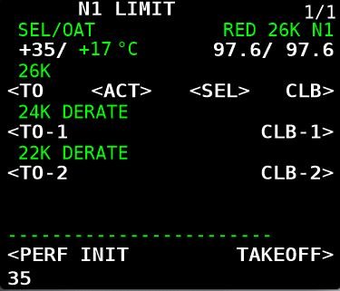
Derates can be assessed on the N1 Limit Page in the CDU. The following derates, applied singly or in combination, are possible:

  • Derated Takeoff Thrust (fixed derate).

  • Assumed Temperature Method (ATM) ; and,

  • Derated Climb Thrust (CLB-1 & CLB-2).

When To Use a Derate

Possible reasons for using or not using a derate are:

  • Environmental considerations (runway condition, weather, wind, etc);

  • Ambient temperature;

  • Airport’s height above sea level;

  • The weight of the aircraft’s load including fuel;

  • Consideration to airline management;

  • The length of the runway; and,

  • Noise abatement.

Electronic Flight Bag (EFB) or Takeoff Performance Tables

A derate is not selected idly by the flight crew. Most airlines use an Electronic Flight Bag (EFB) or another approved source to calculate a suitable derate. If an EFB is unavailable, the aircraft performance data tables in the Flight Crew Operating Manual (FCOM) must be consulted, and the calculations done manually.

Using a derate is not always an option in all situations. For example, in high-performance scenarios, such as heavy takeoffs, high density altitudes, or congested airspace, full thrust may be required. Similarly, a derate may not be suitable if the weather is extremely hot, or if the aircraft is heavy and the runway is short. The final decision on whether to use a derate rests with the Captain of the aircraft.

Thrust Mode Annunciations and Displays

When a derate is used, the thrust mode annunciation (the annunciation is displayed in green-coloured capitals) will be displayed in the Upper Display Unit on the EICAS. The display will differ depending on the airline option.

Possible displays are as follows:

  • TO – takeoff (displayed if no derate is used) - option without derate.

  • TO 1 – derated takeoff 1 - option without double derate.

  • TO 2 – derated takeoff 2 - option without double derate.

  • D-TO – assumed temperature reduced thrust takeoff (ATM) - option with double derate.

  • D-TO 1 – derate one and assumed temperature reduced thrust takeoff (ATM) - option with double derate.

  • D-TO 2 – derate two and assumed temperature reduced thrust takeoff (ATM) - option with double derate.

  • CLB-1 – climb derate.

  • CLB-2 – climb derate.

We will now examine the derates available in the Boeing 737 aircraft.

1 - Derated Takeoff Thrust (Fixed Derate)

A fixed derate is a certified takeoff rating lower than a full rated takeoff thrust. In order to use a fixed derate, takeoff performance data for a specified fixed derate is required (Boeing FCTM 2023). This information is available either from the EFB or from the aircraft performance data tables in the FCOM.

The N1 Limit page in the CDU displays three fixed-rate engine derates: 26000, 24000 and 22000 (26K, 24K and 22K). Selection of a derate will command the software to limit the maximum thrust of the engines to whatever has been selected; nothing is altered on the actual engine. Selecting a derated engine thrust can only occur when the aircraft is on the ground.

Once a fixed derate is selected, it will remain in force until the aircraft reaches acceleration height or a pitch mode is engaged, at which point the fixed derate will be removed.

The N1 for the selected derate is displayed on the NI Limit page, the TAKEOFF REF page (LSK-2L) and in the N1 RPM indication in the Upper Display Unit (%N1 RPM readout and N1 reference bug) on the EICAS.

Thrust Limitation (Fixed Derate)

When using a fixed derate, the takeoff thrust setting is considered a takeoff operating limit. This is because the minimum control speeds (Vmcg and Vmca) and stabiliser trim settings are based on the derated takeoff thrust.

The thrust levers should not be advanced beyond the N1 RPM indication unless takeoff conditions require additional thrust on both engines (e.g., during windshear). If the thrust levers are advanced beyond the N1 RPM indication—such as in the event of an engine failure during takeoff—any increase in thrust could lead to a loss of directional control.

Important Point:

  • A fixed derate can be used on a runway that is either wet, has standing water, or has slush, ice or snow ( provided the performance data supports use of such a derate).

2 - Assumed Temperature Method (ATM)

The assumed temperature method is not exactly a derate; however, it has been discussed because the use of ATM can reduce takeoff thrust.

This method calculates thrust based on a assumed higher than actual air temperature and requires the crew to input into the CDU a higher than actual outside temperature.  This will cause the on-board computer to believe that the temperature is warmer than what it actually is; thereby, reducing N1 thrust. This reduces the need for full thrust, achieving a quieter and more fuel-efficient takeoff.

Using ATM, the desired thrust can be be incrementally adjusted by changing the temperature to a higher or lower value. This can be an advantage to a flight crew as they can fine tune the thrust setting to exactly what is required, rather than using a fixed derate.

ATM is effective only above a certain standard temperature. The 737 Next Generation engines are flat-rated to a specific temperature. In the case of the CFM-56, this is ISA +15°C or 30°C on a standard day. This means the engine can provide full thrust up to that temperature. However, if the temperature exceeds this limit, the engine will produce less thrust. When ATM is used, the temperature must always be set higher than the engine’s flat-rated temperature. Otherwise, the engine will continue to provide full thrust.

Once ATM is selected, it will remain in force until the aircraft reaches acceleration height or a pitch mode is engaged, at which point ATM will be removed.

The desired thrust level is obtained through entry of a SEL TEMP value on the N1 Limit Page (LSK-1L) or from the Takeoff Ref Page 2/2 (LSK-4L).

To delete an assumed temperate the delete key in the CDU should be used.

Thrust Limitation (ATM)

An ATM is not the same as a true derate, even though the takeoff thrust is reduced. This is because when using ATM, the takeoff thrust setting is not considered a takeoff operating limit, since minimum control speeds (Vmcg and Vmca) are based on a full rated takeoff thrust.

At any time during takeoff using ATM, the thrust levers may be advanced to the full rated takeoff thrust (Boeing, 2023 FCTM; 3.17).

Important Points:

  • ATM may be used for takeoff on a wet runway, provided the takeoff performance data (for a wet runway) is used. However, ATM is not permitted for takeoff on a runway contaminated with standing water, slush, snow, or ice.

  • During an ATM takeoff, the yoke may require additional back pressure during rotation and climb.

  • If another derate is selected in combination with ATM, the calculation for takeoff thrust is accumulative. Selecting more than one derate can affect the power that is available for takeoff and significantly increase roll out distance for takeoff.

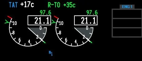
ATM Annunciations and Displays

When ATM is used, the temperature used to calculate the required thrust and the calculated N1 will be displayed:

  • In the Thrust Mode Display in the Upper Display Unit on the EICAS (e.g., R-TO +35); and

  • On the N1 Limit page and the TAKEOFF REF page (LSK-1L & LSK-1R) in the CDU.

3. Combined Derate (Fixed Derate & ATM)

A fixed derate can be further reduced by combining it with the ATM. However, the combined derate must not exceed a 25% reduction from the takeoff thrust.

Thrust Limitation (Fixed Derate & ATM Combined)

When conducting a combined fixed derate and ATM takeoff, takeoff speeds consider Vmcg and Vmca only at the fixed derate thrust level.

The thrust levers should not be advanced beyond the fixed derate limit unless conditions during takeoff require additional thrust on both engines, such as in the case of windshear (Boeing, 2023 FCTM; 3.18).

If the assumed temperature method is applied to a fixed derate, additional thrust should not exceed the fixed derate N1 limit. Otherwise, there may be a loss of directional control while on the ground.

4 - Climb Derate (Derated Climb Thrust - CLB-1 & CLB-2) 

There are two climb mode derate annunciations: CLB-1 and CLB-2. CLB refers to normal climb thrust. To enter a climb derate, the N1 Limit page is opened in the CDU. The possible annunciations are as follows:

  • CLB: Normal climb thrust (no derate);

  • CLB-1: Approximately a 10% derate of climb thrust (climb limit reduced by approximately 3% N1; and,

  • CLB-2: Approximately a 20% derate of climb thrust (climb limit reduced by approximately 6% N1).

The use of a climb derate commands the autothrottle to reduce N1 to the setting calculated by the computer for either CLB-1 or CLB-2. The climb derate begins when the aircraft reaches the thrust reduction height (TRH) or during any climb phase up to FL150.

A climb derate can be selected either on the ground or while the aircraft is airborne; however, if during the climb, the vertical speed falls to below 500 feet per minute, the flight crew should manually select the next higher climb rating (for example, change from CLB-2 to CLB-1). As the aircraft climbs, the climb thrust is gradually reduced until full thrust is restored.

It is a common misconception that using a climb derate will minimise the volume of fuel used; however, this is incorrect.

The use of climb thrust does not save fuel; in fact, it consumes more fuel than full-rated takeoff thrust. However, using a lower climb thrust extends engine life and minimises maintenance. Ultimately, the extended engine life and reduced maintenance costs outweigh the additional fuel expense.

To remove a climb derate, either select CLB on the N1 Limit page or use the delete key on the CDU. The latter method is preferred because it deletes the selected climb derate rather than simply unselecting it.

upper display unit.  THE thrust mode display INDICATES THAT A REDUCED TAKEOFF ATM HAS BEEN SELECTED. IF A DERATE IS SELECTED THE GREEN COLOURED N1 REFERENCE BUG WILL INDICATE THE DERATED THRUST AS WILL THE N1 REFERENCE READOUTS (NUMERALS COLOURED GREEN)

Climb Derate Annunciations and Displays

When a climb derate is used, the derate selected and the corresponding N1 will be displayed:

  1. In the Thrust Mode Display on the Upper Display Unit on the EICAS (the annunciation is displayed in green-coloured capitals);

  2. On the NI Limit page and on the TAKEOFF REF page (LSK-2L) in the CDU;

  3. On the N1 RPM indicator; and,

  4. By the N1 reference bug.

After takeoff, the climb derate will also be displayed on the Climb page in the CDU.

The possible annunciations that can be displayed in the the thrust mode display are:

  1. TO (takeoff without a derate); and,

  2. R-TO (reduced takeoff thrust CLB-1 or CLB-2).

After takeoff, and when the thrust reduction height has been reached, the display will change to whatever climb derate was selected (CLB, CLB-1 or CLB-2).

Important Caveat (all derates):

It is important to note in relation to any derate that the FMC will automatically calculate a corresponding climb speed that is less than or equal to the takeoff thrust. Therefore, a flight crew should ensure that the climb thrust does not exceed the takeoff thrust.

This may occur if a derate or combination thereof is selected, and after takeoff, the flight crew select CLB. Selecting CLB will apply full climb thrust; however, this does not account for any adjustments made by the computer to the initially selected derate. As a result, the climb thrust may be greater than the takeoff thrust.

Boeing Quiet Climb System (QCS) - Abiding with Noise Abatement Protocols

The Boeing Quiet Climb System (often called cutback and referred to by line pilots as ‘hush mode’), is an automated avionics feature for quiet procedures that causes thrust cutback after takeoff.  By reducing and restoring thrust automatically, the system lessens crew workload and results in a consistently less noisy engine footprint, which helps airlines comply with noise abatement restrictions. There are two variables to enter: Altitude reduction and altitude restoration.

During the takeoff checklist procedure, the pilot selects the QCS and enters the height AGL at which thrust should be reduced.  This height should not be less than the thrust reduction height. The thrust restored height is typically 3000 feet AGL, however, the height selected may alter depending on obstacle clearance and the noise abatement required. 

With the autothrottle system engaged, the QCS reduces engine thrust when the cutback height is reached to maintain the optimal climb angle and airspeed. When the airplane reaches the chosen thrust restoration height (typically 3,000 ft AGL or as indicated by noise abatement procedures), the QCS restores full climb thrust.  Note that the minimum height that the QCS can be set is 800 feet AGL. 

The two heights referenced by the Quiet Climb System can be modified in the CDU (TAKEOFF REF 2/2 page (LSK-5R)). The system can be selected or unselected at LSK-6L (on/off).

Multiple Safety Features for Disconnect

The Quiet Climb System (QCS) incorporates multiple safety features and will continue to operate even in the event of system failures. If a failure occurs, the QCS can be exited by either:

  1. Selecting the takeoff/go-around (TOGA) switches on the throttle control levers, or

  2. Disconnecting the autothrottle and controlling thrust manually.

ProSim737

The Quiet Climb System was previously a component of the ProSim737 avionics suite; however, it was removed with the release of version 3.33. It is now available only in the professional version of ProSim737, not in the domestic version.

As a result, if a takeoff requires noise abatement, the necessary calculations and settings must be performed manually. This process is not difficult, as a fixed derate, ATM, or a combination thereof, along with the acceleration height, can be entered or adjusted based on the requirements of either an NADP 1 or NADP 2 procedure.

Figure 2: For completeness, and to provide an example of the altitude above ground level (AGL) that a noise abatement procedure uses.

Figure 2: Noise Abatement Departure Procedures (NADP). (click image for larger view).

Similarity of Terms

When you look at the intricacies of the above mentioned functions there is a degree of similarity. This is because all the functions center around the height above ground level, in what is a time critical phase of flight (the takeoff and initial climb)

The way I remember them is as follows:

Thrust Reduction Height is the height above ground level (AGL) at which the takeoff thrust will be reduced by a few percent N1. This is done to preserve engine life and reduce overall maintenance. Thrust reduction height is also when the takeoff thrust changes to climb thrust; and

Acceleration Height is the height above ground level (AGL) at which the aircraft’s nose is lowered to increase airspeed. Flap retraction typically begins at acceleration height;

Derated Takeoff Thrust is when the N1 of the engines is reduced (26K, 24K or 22K). This is done prior to takeoff;

Assumed Temperature Method (ATM) is when the N1 is lowered by changing the ambient temperature to a higher value in the CDU. This is done prior to takeoff;

Climb Derate (Derated Climb Thrust - CLB-1 & CLB-2) is when the N1 used during the climb phase is set to a lower power setting. Selecting a climb derate can be done either prior to takeoff or when the aircraft is airborne; and,

The Quiet Climb System enables a minimum and maximum height to be set in the CDU; thereby, reducing engine power and engine noise.  The restoration height is the height AGL that full climb power is restored.  The QCS is used only for noise abatement.

Final Call

Acceleration height, thrust reduction height, and derates are critical elements in optimising the takeoff performance of the Boeing 737.

Acceleration height is the altitude at which the aircraft’s nose is lowered to gain speed and the flaps are retracted, while the thrust reduction height determines at what height above ground level (AGL) to reduce engine power, from takeoff thrust to a lower setting. By adjusting the engine thrust settings and applying derates, operators can enhance engine longevity, improve fuel efficiency, and reduce noise during takeoff.

Understanding and properly applying these settings not only ensures compliance with performance regulations, but also contributes to operational efficiency. Ultimately, these parameters enable operators to maximise safety, minimise fuel consumption, and optimise aircraft performance during takeoff.

  • Acronyms Used

  • AH – Acceleration Height

  • AGL – Above Ground Level

  • CDU – Control Display Unit

  • CLB-1 & CLB-2 – Climb 1 and Climb 2

  • DERATE – Derated Thrust

  • FL – Flight Level

  • FMC – Flight Management Computer

  • LSK-1R – Line Select 1 Right (CDU)

  • ‘On The Fly’ – ‘On the fly’ is an idiomatic expression often used in casual or conversational contexts to mean something done quickly, without preparation, or while in motion.

  • PFD - Primary Flight Display

  • QCS – Quiet Climb System

  • TMD – Thrust Mode Display

  • Vmca – Defined as the minimum speed, whilst in the air, that directional control can be maintained with one engine inoperative.

  • Vmcg – Defined as the minimum airspeed, during the takeoff at which, if an engine failure occurs, it is possible to maintain directional control using only aerodynamic controls. Vmcg must not be greater than V1.

Updates

07 March 2025

Gallery: Various screen grabs from the CDU showing the effect on %N1 for various fixed derates and Assumed temperate (ATM).

Simulator Construction Update - June 2013

Building has been rather slow the last couple of months, although design wise quite a bit has been accomplished.  My main hurdle has been waiting for the replacement throttle quadrant and pedestal to arrive from the United States. 

The throttle has taken considerable time to correctly interface to allow full automation, and the initial brief has been changed to enable the interface cards that the throttle uses to be housed in a dedicated interface module.  The interface module is a trial to determine the feasibility of a modular design.

it's unfortunate, that building cannot continue in earnest until the throttle, pedestal and master module is installed.

I’ve been reliably informed that the new unit is expected to arrive sometime in late August.  There are some surprises in store which I’m sure you will find interesting.

In the meantime, I’ve been busy searching for and purchasing second-hand Boeing parts for some panel additions to the center pedestal and acquiring OEM 737 toggles, switches and bits and pieces for the forward and aft overhead panels.

Construction posts will continue shortly, however, until then I’ll continue to publish posts pertaining to operational procedures for the 737-800.

As with all my posts, if you find a glaringly obvious mistake, please tell me so I can rectify the discrepancy.

Searching for Definitive Answers - Flight Training

First Officer conducts pre-flight check list & compares notes.  Whilst check lists are essential in ensuring that all crews operate similarly, there is considerable variance in how flight crews actually fly the 737

Learning to fly the 737 is not a matter of 1, 2, 3 and away you fly; there’s a lot of technical information that requires mastering for successful and correct flight technique.  Searching for a definitive answer to a flight-related question can become frustrating.  Whilst respondents are helpful and want to impart their knowledge, I’ve learnt through experience that often there isn’t a definitive answer to how or why something is done a certain way.  

Typical Pilot-type Personalities

Typical pilot personalities nearly always gravitate towards one answer and one correct method; black or white, right or wrong – virtual pilots or “simmers” behave in a similar fashion.  They want to know with certainty that what they are doing replicates the correct method used in the real-world. 

In reality, the Boeing 737 is flown by different crews in different ways all over the globe every minute of the day.   Often the methods used are not at the discretion of the crew flying, but are decided by airline company policy and procedures, although the ultimate decision rests with the Captain of the aircraft.  

For example, climb out procedures vary between different airlines and flight crews.  Some crews verify a valid roll mode at 500’ (LNAV, HDG SEL, etc) then at 1000’ AGL lower pitch attitude to begin accelerating and flap retraction followed by automation.  Others fly to 1500' or 3000’ AGL, then lower pitch and begin to "clean up" the aircraft; others fly manually to 10,000’ AGL before engaging CMD A. 

Another example is flying an approach.  Qantas request crews to disengage automation at 2500’ AGL and many Qantas crews fly the approach without automation from transition altitude (10,000’ AGL).  This is in contrast to many European and Asian carriers which request crews to use full automation whenever possible.  In contrast, American carriers appear to have more latitude in choosing whether to use automation.

Considerable Variance Allowed

The below quote is from a Qantas pilot.

  • There is considerable tolerance to how something is done, to how the aircraft is flown, and what level of automation , if any, is used. Certainly whatever method is chosen, it must be safe and fall within the regulatory framework. There are are certainly wrong ways to do things; but, there is often no single right way to do something.

Therefore; when your hunting for a definite answer to a question, remember there are often several ways to do the same thing, and often the method chosen is not at the crew’s discretion but that of the airline.

Genuine B737 Forward & Aft Overhead Panels Purchased

For some time I’ve been debating whether to use a reproduction or OEM forward and aft overhead panel.  I have been favouring an OEM panel as this is in line with using genuine parts in the simulator, however, the overhead is a complicated piece of kit and ensuring complete functionality would be a challenge.

RIGHT:  Forward Overhead Panel.  The centre panels will be replaced to conform to a 737 Next Generation.  Panel was removed from a United Airlines 737-300 aircraft.

Certainly, using an overhead panel made by Flight Deck Solutions (FDS) is an easier option, however, despite their reproduction panels being high quality, there are discernible differences between reproduction and OEM panels.  

OEM 737 Overhead Panel Purchased

My decision was made for me when I was told a forward and aft overhead had become available from a recent 737 pull down.  Rather than remain indecisive, I thought I’d jump in “boots and all” and purchase it.  The two overhead panels have come from B737-300 and include the frames, DZUS rails, center panels, Cole engine starter switches, landing gear toggles and various other knobs and toggles.

I’m impressed at the condition of the panels; usually when panels are removed from an aircraft in a tear down yard there is little care given, and the frames become scratched, dented, or damaged in some way.  The frames I have purchased appear to be in relatively good condition.  

Cole Switches

I was fortunate that the two engine starter switches (Cole switches) were included.  These switches are made to exacting requirements and use a solenoid mechanism. 

LEFT:  Difficult to find operating Cole switches are used on all Boeing airframes from the 727 through to the Next Generation.

Purchasing Cole switches individually is quite expensive, so I'm pleased they were not striped from the overhead.

Panels and Backlighting

When I began to construct the simulator in mid 2011, I was adamant that backlighting should match that of the MIP, throttle quadrant and center pedestal.  I believe it was around 2006 that Boeing began to replace bulbs in favour of LEDS.  Certainly, the latest made Boeing uses LEDS. Therefore, my opinion has changed and I am happy to mix bulbs and LEDS (within reason)

The use of bulbs in the overhead uses a lot of power and generates considerable heat; using LEDS minimises power consumption and produces less heat.  If the LEDS are installed correctly, their resultant light is very similar to that of bulbs, and the brightness observed in the real aircraft.

Ultimately the back lighting will be dependent on whether I decide to use older style genuine Boeing panels or reproduction panels.

Realism & Authenticity - How Far Do You Go

Some flight deck builders go to extremes to ensure their flight decks replicate exactly what is seen in the real aircraf,t and while this is admirable, this is not the route I am 'religiously' going to travel.  There has to be compromise between replicating something exactly and having a functional flight simulator.

The end product will  be a combination of genuine (OEM) and reproduction parts - mostly OEM.

Furthermore, serious thought must also be given to how the overhead is going to be installed to the simulator; whether it be to a shell, such as produced by FDS or to a custom-made roll cage assembly.

I'll keep the Blog updated as parts are found and the overhead is developed.

  • Unfortunately I do not have any high quality pictures. These images were supplied by the vendor. Currently the overhead is still located in the US.  In time better quality images will be uploaded.

B737-800 Cabin Phone System Panel - Center Pedestal

oem 737-800 cabin phone panel: Panel has three push buttons with backlighting and legends, and one toggle button

I recently acquired an avionics panel that is a little different to the norm.  The panel was acquired from a company that was responsible for altering the on-board communication system for 50 Boeing 737-800 jetliners; the aircraft were being refitted with global communication equipment.  The upside for me was that the panels were being decommissioned and were not required by the supplier.

Late model 737 Next Generation panels are uncommon to find; therefore, it is interesting to observe the differences between the older style classic panels regularly seen on e-bay, and a newer style panel. 

The first thing that comes to mind, other than condition, is the lack of a rear box assembly on this panel.  Instead of an aluminum box, the wiring is protected by a stainless bracket assembly.  The wiring harness is also more refined and neater looking, while the backlighting, rather than using 5 Volt bulbs uses LED technology.

oem 737-800 cabin phone panel. note the crispness of the legend

LED Technology

Most people are familiar with the 5 volt incandescent bulbs used to illuminate the light panels in Boeing aircraft - the bulbs produce a soft yellow-orange hue.  The colour temperature is in stark contrast to the white hue produced by LED technology. 

I believe that airframes post 2006 utilise LED technology.  Notwithstanding this, until older airframes are phased out, panel lighting will be a mixture of incandescent and LED lighting, or a combination thereof. 

Matching Colour Hue

Attempting to match the backlighting colour hue, especially in the center pedestal and overhead panels has always been a challenge for flight deck builders, especially when using an assortment of older style OEM panels and panels made by differing companies (FDS, CP Flight, Open Cockpits, SimWorld, etc).  

Wiring is very neat and the panel does not utilise the more commonly found aluminum box structure

What many virtual pilots forget, is that the only purpose for an airlines’ existence is to generate income and a profit for the company. Pilots on the other hand are more concerned with flying the aircraft. 

There is very little thought as to whether a panel's backlighting is the same colour hue throughout all the panels.  If and when a panel needs to be replaced, a technician’s only concern is getting a workable and certified instrument fitted into the aircraft as quickly as possible. 

it is not unrealistic to have a few LED panels scattered amongst older bulb illuminated panels

Cabin Phone System Panel - What Works

Although there is no obvious use for this panel in the simulator, it is a good-looking panel that improves the overall aesthetics - it fills a 'gap' in the three-bay center pedestal.  The buttons do function and when depressed change colour and provide different cautionss.  Lifting the red cover and pushing the toggle to test causes the third button to illuminate 'smoke' in orange.

Although the panel has not been connected to an interface card, it is an easy process to connect a PoKeys or Leo Bodnar interface card to the Canon plug. ProSim737, nor Sim Avionics include functionality with this panel.

Purchase Guidelines - Avoid Being Disappointed

737-800 flightdeck (simulator)

Based on feedback from my previous journal post, I decided to write a few lines dealing with what we, as simmers and virtual pilots, should expect from manufacturers and sellers.  This post is more directed to those entering the hobby rather than experienced builders; those that have been in the 'game' long enough already know the 'do's and don'ts'.

In comparison to other more main-stream hobbies, flight simulation is relatively uncommon and specialized, and as with fishing, hiking, dog grooming and gardening, a plethora of companies have sprouted to supply the enthusiast with an assortment of “essential” add ons from panels and quadrants to books and magazines.  Some manufacturers are large companies and others small “one man bands”.

'Caveat Emptor'

It is unfortunate, that even in our small community; all potential buyers must be conversant with the term 'Caveat Emptor' meaning in Latin 'Let the buyer beware'.  Nobody is immune from the unscrupulous seller whose only want is to remove the hard-earned cash from your wallet or pocket book.

Since beginning the development of the B737 simulation two years ago, I have come into contact with many companies and individuals; some respectable, reliable and very honest, and others that live in the silt, that swirls around in the bottom of the barrel.

The small number of 'bottom crawlers' (without being offensive towards trilobites and other invertebrates) include not only those that sell reproduction parts, but also those that sell real secondhand aviation parts.  One seller of real aviation parts lists and shows a picture of one item on his website, however, dispatches a different lower quality item. 

Do you have recourse - NO!   Once you have parted company with your money it is is gone forever...... 

Supply, Demand & Payment

One theme common to many suppliers is the time it takes to supply a customer with their product.  This is especially evident when commissioning manufacturers to produce and supply hardware associated items such as yokes, panels and the like. 

Suppliers always want their money up front and nearly always promise supply forthwith.  Unfortunately, this rarely happens.  Any number of excuses are promulgated: I’m busy, too many orders, lack of staff, waiting on parts, postal service delays, sickness – and the worst of all - no contact despite e-mails being received..

This is not to say that all companies and individuals selling flight simulation products have a poor reputation; this would be incorrect.  There are many sellers that provide first rate service that cannot be bettered.  It is unfortunate that all businesses do not subscribe to this philosophy.

Forums

It is an easy task to “troll” through one of several flight simulation forums and read the common threads evident in many of the posts published by disgruntled customers.  If a common theme is duplicated in several threads, such as: delay, problems, glitches, bad communication or minimal contact, then why expect your experience to be different.

"past experience is a prime indicator to future performance".

Do Not Accept the Risk

I think anyone who has been involved with the industry for any length of time, has a horror story to tell.  

It ceases to amaze me that many potential buyers that have read the threads on the forum and asked the correct questions, still proceed with an order and send full payment to an unscrupulous company or individual.  It is almost as if they want the product so badly that they are happy to accept the risk!  Then, after they have been let-down they post their story to a forum.  

Unfortunately, this behavior only goes to strengthen the resolve of the suppliers that continue to behave in this manner.  If you look at the supplier’s point of view, why should they improve their performance if there is any number of purchasers willing to order and pay for something in advance. 

There is no incentive to change!

The only way the supplier will alter their behavior is if you, the customer, alter your behavior.

I'm not suggesting that a vendor will "run" with your money, but there have been instances of vendors suffering financial problems which culminated in them liquidating their business.  If you have paid in full before production occurs, and a financial problem develops, then retrieving your money will probably be difficult. 

Purchase Guidelines

Before any purchase:

  • Do your research.  Know your product and know what you want for your set-up.

  • Ask others regarding their experiences with a company or individual.

  • Read the forums, learn to use the search functionality on each forum and contact members who use the same item you wish to purchase.

  • Ask on a forum whether a manufacturer is reliable, prompt and does good work.  Building a flight deck is a detail thing; it’s not hammer and nails mentality.  Why employ someone who is not into detail...

  • Try to only pay a deposit, despite being told otherwise. 

  • You are the customer and you have a right (obligation) to ask anything you want of a manufacturer.

  • Secure an accurate time-line in writing to when an item will be supplied.

  • Ask about a return policy should you not be happy with the items purchased.

  • Finally, if the information you are told by several people is identical – then BELIEVE this information and don’t make the purchase. 

Instead, contact the supplier and tell them your concerns and reasons why you will not be buying from them.  Often when you do this, the supplier will alter their behavior to accommodate you.  After all, they want your money!

Guidelines for purchasing real aviation parts

  • If an item looks a bargain it generally is not…..

  • Always check on return policy.

  • Only purchase from E-Bay from sellers with a solid positive feedback rating.

  • Pay via PayPal if possible as PayPal will provide buyer protection.

  • If the advert states "not checked, unsure if working or similar", then expect the item will be broken.

  • Assume nothing.  Assumption is the "Mother" of all ClusterFucks".  A "CluserFuck" is a military word meaning multiple problems (see definition a bottom of page).

  • Pay a little more and purchase ONLY from reputable, reliable and honest dealers.

Have I been caught before – of course!  Will I get caught again – not likely, hopefully not....

Definitions

'CluserFuck' - Military term (mainly American) for an operation in which multiple things have gone wrong. Related to 'SNAFU' (Situation Normal, All Fucked Up") and 'FUBAR' (Fucked Up Beyond All Repair).

In radio communication or polite 'conversation (i.e. with a very senior officer with whom you have no prior experience) the term 'clusterfuck" will often be replaced by the NATO phonetic acronym 'Charlie Foxtrot'.

SISMO Soluciones - Avionics Review: My Negative Experience

I initially wasn't going to document my negative experience with Sismo Soluciones as many simmers use SISMO products and are fiercely loyal to this company.  This post has sat unpublished for close to 10 months until a friend convinced me otherwise, saying that bad reviews can be beneficial, especially to new simmers who are undecided on what and whom to purchase from.

This is the first negative review I have written and in doing so realise that I will no doubt annoy some people, especially loyal SISMO customers.  My aim is not to annoy, intimidate or create malicious rumours.  Rather, it is to share with others my factual experience with this company. Due to the negative nature of this review, it WILL NOT be posted to any forum.

I purchased the following units from SISMO:

  • ADF radios (2)

  • Transponder / ATC radio

  • Audio Control Panel 

  • rudder trim module

At the time, I was using Sim Avionics as my avionics suite.

I had issues with: aesthetics, quality assurance and the use of the SC Pascal script.  

When you initially look at the modules offered by SISMO, they do look attractive; however, it's often the small things that count and the panels made by SISMO lack the attention to detail and quality expected.

  • This article is a little different from previous articles.  I've made a basic review of the modules, then discussed the issues I had in respect to with the panels/modules.  Finally I've discussed company.

Please note that I use the word panels/modules interchangeably.

Overall Module Construction and Appearance

The modules are constructed from acrylic and painted in Boeing grey.  The use of CNC machining produces a crisp finish resulting in cut-out lettering that is well defined.  This enables the lettering to appear very crisp when the panels are back it.  The buttons and switches used in the panels are machine injection moulded and secured to rotary stems via two small grub screws. The electronics are not sealed pr boxed (such as in CP Flight) but are visible.  DZUS fasteners are not included although holes have been drilled in the appropriate position (although these holes are too small to fit genuine DZUS fasteners).  The backing plate is made from plastic.

Paint Work

The paint work used by SISMO is not of a high quality.  The paint, eith minimal use of the panel, wears thin on the panel beneath the knobs and switches.  The paint also chips very easily and is not evenly applied to include the side of the unit.  Although I don’t know how many layers of paint have been used, I’d suggest it’s minimal.  Minimal paint saves time and expense and does not lend itself to high quality or longevity.

Integrated Backlighting (IBL)

SISMO ADF unit & FDS NAV1 unit.  Note the difference in backlighting (not seven-segmented displays) and module colour between the two units.  FDS use real aircraft bulbs

SISMO does not utilise real aircraft bulbs for backlighting.  Rather they use a number of strategically placed LED lights.

There are several arguments for and against the use of bulbs and LEDs.  The former provide a realistic throw of light at the correct colour temperature, while LED’s are usually more pin point, require less power to run, and usually appear colder in colour temperature.

The Backlighting on the SISMO modules is reasonable; however there is not an even throw of light across the rear of the panel to allow complete illumination of all cut out lettering.  The panel also does use a light skirt to inhibit stray light from illuminating the outer edge of the modules  The backlighting is powered by 12 volts.  The colour of the LEDS is amber yellow or warm orange.

I had an issue with two LED lights; The LED lights stopped working.  SISMO informed me I would have to repair this myself.  Shortly thereafter, a third LED light failed. This suggests that SISMO may have a quality issue in relation to the LEDS they use (at least in the batch I received).  I have little doubt that the LEDS are inexpensively sourced from China (ROC).

Electronics

The upper panel of the module is attached to the electronic circuitry within the lower section by a backing plate made from plastic.  It should be constructed from metal to aid in strength.  The electronics appear substantial and to be well built (appearance only as I did not bench test the electronics). 

System and I/O Cards

The modules are not standalone devices.  Depending upon your requirements, the modules require connection to various system and sim cards for complete operation.  As an example, to operate the ADF units and rudder trim module requires three GIC connection cards, an Ethernet motherboard card, and three servo-daughter cards – seven cards in total!  


figure 1: sismo card setup. there are lot of cards


Although there is nothing wrong with this method of operation, it does pose a challenge to find a suitable location to mount the cards.  The cards appear to be constructed to a high standard and are very solid; they do not feel or look like cheap Chinese-made cards.

I’ve included, for interest, a schematic wiring and card diagram of the module set-up for the Captain-side ADF radio. (click the image to enlarge the picture). 

The main Ethernet mother board requires a 5 volt power supply.

Wiring

SISMO provides you the opportunity to either use their prefabricated flat cabling or to wire everything yourself.  I choose the former and this saved a lot of time and frustration (wiring and soldering).  The flat cable packs are each fitted with heavy duty plastic clips for attachment to the cards.  Connection is straightforward and SISMO provide large A3 colour wiring sheets so you know exactly what wire plugs into what card.

If you decide to use the flat cabling, it’s necessary to include in your system a number of additional cards.  These cards, called  Generic Interface Cards (GIC) act as joiners between the different system cards used by the panels. The size of each GIC card is little larger than a credit card. 

SISMO panels with flat cabling.  There is a lot of cables that need to connect with several interface and GIC cards

Too Many Cards

The amount of wiring and number of cards needed to use SISMO products is ridiculous! 

Using four panels, the interior of the center pedestal is a mass of wires leading to and from various interface cards.  There are far better and easier alternatives available from other manufacturers.  

The Power of Ethernet

SISMO’s product range utilises Ethernet technology rather than USB; this has many advantages over the use of USB. 

According to SISMO literature: 'USB was not designed to carry the volume of information necessary for flight simulation. Although USB is practicable and does work very well, it can on occasion malfunction (drop out), or slow the operation of the intended device by creating a bottleneck for information flow.  Ethernet, on the other hand, has been designed at the onset to allow for high information flows ensuring fast and consistent transfer of information'.

An Ethernet cable is required to link the main Ethernet mother board, either directly to the computer or to a switch (if using two or more networked computers).

The two tabs overlap the OEM DZUS rails.  You must cut the DZUS rails to allow the module to fit the pedestal

Real B737 Center Pedestal - Not Drop & Fly

An important point to note is that the ADF and ATC radios will not drop directly onto the DZUS rails fitted within a real B737 center pedestal. 

SISMO modules have been designed so that the electronic boards, mounted directly beneath the panel, are flush to the edge of the panel.  What this means is that the panel cannot be placed directly onto a rail, as the electronics board abuts the edge of the rails. 

To allow correct placement in a genuine center pedestal requires that the DZUS rails be cut in the appropriate position.

All the other SISMO modules, other than the ATC and ADF modules drop onto the rails without an issue.  I'm unsure why this manufacturing inconsistency has occurred.

Misleading Information

During my initial research, I asked SISMO if their panels fitted a genuine center pedestal.  I also queried if OEM DZUS fasteners could be used.  Juan Ma (sales) stated that all SISMO panels were DZUS compliant and did fit genuine DZUS fasteners; however, when I told SISMO they didn't fit the rails, Juan Ma claimed he had misunderstood my question due to his poor understanding of the English language - he meant to say no rather than yes.

To utilise OEM DZUS fasteners, you will need to enlarge the attachment holes in each of the panels to enable the fastener to fit into the hole.  A word of caution here – SISMO use plastic backing boards which will crack easily if you are overzealous with a power drill (this is why I suggested, earlier in this article,  that metal be used.

Communication and Support

Support for SISMO is either directly via e-mail or by their dedicated forum.  All e-mails are answered quickly (in English or Spanish). JuanMa and Cristina answered all my e-mails in a professional level.  They are courteous, exceptionally patient, and very helpful; both strive to help you as much as they can.  

SISMO Modules - A Closer Inspection

ADF Radio Module

Initially, you’re impressed when you look at the ADF panels.  The seven segment displays, illuminated in either amber yellow or warm orange are easy to read, well lit, and appear similar to the displays you would see in a real aircraft. 

As you turn the rotary knobs to change the frequencies there is no catching as the knobs are turned, and the push-to-activate buttons move freely.  They do not stick in the down position when depressed. 

Problems

One small issue I immediately noticed, was that the tinted window plate which sits over the frequency display is not secured; as opposed to other manufacturer’s modules that incorporate the plate into the actual construction of the panel.  If you invert the modules the cover plate will fall out of the recess.  I decided this wasn’t a problem; how often are simulators inverted, and securing the plate is an easy exercise.  A small piece of double-side tape is all that is needed to secure the plate in place.

My problems began after roughly four hours of use.  The frequency push-to-activate button was temperamental and would not allow the stand-by and active frequency to be changed with one push; several pushes were required.   The problem was intermittent, but investigation suggested an issue with the clicking mechanism or the button itself.

The next issue to develop was with the rotary knob; turning the knob caused the frequencies to jump digits.  As with the push-to-activate button, the problem was intermittent but, the problem was rectified when you closed and reopened the SC Pascal script.  Perhaps the script needed tweaking.

Knobs and Switches - Poor Quality

I was disappointed with quality of the switches and knobs used on the panel.  The two ADF-ANT switches are made from hand injected low quality plastic; several small injection holes in the plastic are easily seen.   For the minor cost involved, high quality machine-injected knobs could have been manufactured.  

Each of the ADF-ANT switches slides onto and over the plastic circular shaft of the rotary mechanism.  The knob is then secured to the shaft by two grub screws each side of the knob.  It doesn’t take too long for the grub screws to begin to loose their grip on the shaft with resultant slippage of the knob.

Other companies have solved this potential problem by using D-shaped shafts or higher quality rotary switches incorporating metal shafts instead of plastic.  Knobs manufactured by high-end companies use stainless steel shafts and stainless grub screws that screw into stainless sleeves.

  • My rating 4/10

Audio Control Panel (ACP/ASP)

SISMO ACP unit does not look realistic with inexpensive poorly moulded buttons and very stark backlighting.  Note that some of the rectangular buttons are not in alignment.  This unit has been constructed with very poor attention to detail.  Note, the black knob is not a SISMO knob but comes from a 737CL (OEM)

The Audio Control Panel (ACP/ASP) replicates the audio system of the B737 (navigation radios, etc).  The ACP occupies a large piece of real estate in the center pedestal and the ability to turn on and off navigation audio sounds should not be dismissed.

The main ACP switch is of similar construction to the ADF-ANT switches on the ADF module; it is poor quality with injection holes readily observed.  The clear push buttons used to turn on and off the various audio sounds are of low quality.  The buttons are fashioned from clear acrylic and lack detail and definition.  

I was disappointed, that when the ACP unit was fitted onto the pedestal, light from the backlighting seeps along the edge of the panel (to stop this I applied masking tape to the side of the panel to create a light skirt.  I also noted that some of the buttons are not accurately aligned with one another. 

Often it’s the small things that count and push a product to the next level. Clearly this is not a mantra that SISMO adhere to.

I was not impressed with the quality and attention to detail on the SISMO ACP unit; therefore, have decided to convert two real B737-500 ACP panels to simulator use.

  • My rating 2-10

Rudder Trim Module

The rudder module incorporates a large knob that is center-spring loaded.  The knob allows the rudder to be deflected in either direction and be recorded in degrees of offset on the scale.  The movement of the defection needle is made possible with the use of small servo motor fitted beneath the module and powered by 12 volts.

SISMO rudder trim module.  Note the very poor moulding on the knob and colour shift with lighting

The rudder trim knob is poorly moulded and clearly portrays hollow holes left over from the injection process.  For those searching for aesthetics, replacement using a real B737 knob is very easy (if you can find a real knob).

The trim needle, at least on my module, is a little lop-sided.  As with the ACP module, stray light from the LED backlighting is readily seen around the edge of the panel.  Like other SISMO panels, there is no inclusion of a light skirt to stop stray light.

The remainder of the module is aesthetically pleasing.

The rudder trim is one of the modules that is necessary to complete a center pedestal, but unless one is regularly flying with one engine, the module is seldom used.  Therefore; this module from SISMO, even with the irregularities, is a reasonably priced alliterative to some of the more expensive counterparts available (provided a replacement knob is used and light skirt is fabricated).

  • My rating 5-10

ATC (Transponder) Module

This is one of the better produced modules from SISMO. 

The switches and knobs are manufactured to a quality at least equal to what other companies produce.  There are no injection holes in the knobs, and turning the frequency knob is very smooth when altering frequencies. The digital read out is crisp, yellow amber in colour, and the tinted window, which falls out easily on the ADF panel, seems to be more secure (although it is the same drop in type).   As with the ADF panel, this panel will require you to cut the DZUS rails if you are using an OEM 737 center pedestal.

As a script was never supplied with this module (SISMO did not send it), I cannot provide information to how well it operated.  

  • My rating based solely on appearance is 7/8-10

Reliability and Performance - Software and Modules

Software - SC Pascal Scripts

The modules require SC-Pascal scripts to be installed on the simulator computer. 

The basic script is downloaded from the SISMO website.  A further customised script is needed to configure the modules to the avionics software package you are using (Sim Avionics, Project magenta, ProSim737, Orion, etc) and FSX.  SISMO write the script dedicated to the panels you are using.  To activate the panels you run the executable file when you open a flight session.

SC-Pascal scripts are completely new to me, but a little research indicates that the script is used as a software interface between the actual functionality of the various panels, FSUIPC and simulator software.

Once the scripts are installed and configured correctly, a folder is created in which is stored the config.ini file and the executable script.  The folder and files can be named and stored anywhere on your computer system.   The panels are turned on by activating the executable script (.exe).  

As an option, direct access to the script can be made by adding the executable command to the auto start folder of your computer.  This option automatically starts the modules when the computer is turned on.  The script then runs in stand-by mode until flight simulator is turned on.  This option saves time and repetition by not having to turn on the executable file.

As SISMO utilises Ethernet technology, the various IP addresses of the computer (s) you are using need to be correctly configured to allow communication between the computer and the panels.  This is basic networking knowledge and is relatively easy to learn.

Once the software is configured, the software and modules should function flawlessly.  

Script Problems

I did have some issues with the SC Pascal script freezing when it was initiated.  The script also caused some issues which appeared to cause the ADF radios to incorrectly display frequencies.  To Juan Ma's credit, he did tweak the script, however, the problems remained.

As I know nothing about SC Pascal scripts, I don't know with certainty whether the problems experienced were caused by a script issue, hardware issue, or something particular to my system.  If push comes to shove, my guess is that the problem lay with the SC Pascal script.

I try to keep things simple in my simulator, and running multiple scripts for various panels through several interface cards doesn't exactly fit into this ethos. 

It would be inaccurate to state that SC Pascal scripts don't work, because there are many enthusiasts who have them operating perfectly.  But, I am not one of these individuals.

Note that I was using Sim Avionics.  If using ProSim737 there is an option to use a script or direct drivers within ProSim737.

Quick List - Pros and Cons

PROS

  • Fairly accurate 1:1 ratio (or close to)

  • Easy to install and use software (knowledge of SC Pascal required if altering software)

  • Laser cut and stenciled lettering

  • Ethernet technology

CONS

  • Plastic shafts on ADF-ANT knobs (should be metal/stainless)

  • Poor quality knobs and switches on ADF, ACP and Rudder Trim module

  • Average light coverage for LED backlighting

  • ADF and ATC modules don't drop directly onto DZUS rails; the rails must be cut.

  • Large number of cards needed for operation

  • Not DZUS complaint (requires existing holes to be enlarged)

  • Plastic backing plate on panels (easily damaged when enlarging holes for DZUS fasteners)

  • Light seepage around edge of some panels from backlighting (no light skirt)

  • SC Pascal script troublesome and works intermittently.

  • Poor quality paint work

Considering the above, the panels are expensive.

Final Call

The modules are ideal for the budget-conscious flight simmer.  This said, a potential user must have knowledge to troubleshoot problems.

The lack of quality knobs, switches and poor attention to detail detract aesthetically, while the large number of cards that need to be installed can make installation challenging.  Three failing LEDS and problems with the frequency selector switch on the ADF radio panel may point to quality assurance issues.  The use of Ethernet over USB is highly commended and may reduce information bottlenecks.

My rating for the software is 4/10 (The supplied scripts didn't work with my system, which at that time was Sim Avionics and not ProSim737).

My overall rating for the modules is 3/4/5-10 (based on fitting issues, quality of knobs, poor attention to detail, poor painting, no light skirts and temperamental frequency selection switches on ADF).

Please note that this review is my opinion only and is not endorsed.

POST SCRIPT: - July 15, 2012 - RETURNED MODULES TO SISMO REQUESTING REFUND

I have returned all the panelss, cards and wiring  o SISMO for a full refund (minus freight).

Initially, SISMO offered me 10% of the value of the products purchased (this included the interface cards that had never been used).  

SISMO stated that the return period had been exceeded, and any products returned would be treated as second hand units.  It didn’t matter that SISMO had not, at that time, sent all the appropriate SC Pascal scripts to ensure correct operation of the modules.  

The writing of the SC Pascal scripts was delayed close on 2 months after I received the modules, and when received, the scripts didn't funcyion as intended.  Excuses were; staff holidays, workloads, Easter break, and awaiting confirmation from another company to facilitate operation.  

Upon receipt of the returned items, SISMO claimed that many of my issues were incorrect or not relevant.

  • They claimed that the modules had been damaged.

  • They stated that I had broken the LEDS (I told them the LEDS were not working when I received the parcel).

  • They claimed I had disassembled the units and damaged the paint and screws.

  • They claimed I had re-painted portions of the units.

  • They claimed sticky plaster was attached to one of the units. (this is correct as I used tape to secure the wiring & also to create a trial light skirt)

  • They deducted from my refund, Spanish import duty and inspection fees (returned the goods to Spain).

  • They claimed I did not include paperwork (which I did). 

  • They stated that as the ATC RADIO module was discontinued, a refund was not possible.  At the time of purchase they did not inform me this panel was discontinued.

I'm not going to go into a long account to what has transgressed.  But, I will say that this company cannot be trusted…..They promise the world to you, but if you aren't happy with the products, they provide every excuse possible to NOT provide an adequate and reasonable refund.

For example, when I reported the failure of the LEDS to SISMO, their response was 'they worked when they left the shop'.  They did offer to replace the LEDS but, at my shipping expense (which was expensive).  They also offered, because of the inconvenience caused, a discount on further purchases.

It should also be noted, that in my initial correspondence with SISMO, I asked whether their panels would drop directly into an OEM B737 center pedestal.  Juan Ma stated 'YES'.  However, on receipt it was discovered that the modules were too large to fit directly onto the pedestal DZUS rails.  I queried Juan Ma from SISMO on this; he stated that it was a language misunderstanding.

Juan Ma understood perfect English when it came to avoiding a refund of purchase money.

Legislation, PayPal and Delays

Spanish legislation states that every purchase has a 7 day cooling off period, in which a return and refund can be made.  PayPal policy states you have 45 days in which to make a claim.  EU legislation states that refunds are possible if items do not function correctly - within a set time frame.

Without a working script for Sim Avionics (which took two months to receiveve), how can testing of panels occur.  Because of the approximate two month delay on sending operating scripts to me, all options available to me had expired.

I cannot help but think that SISMO delayed the sending of the scripts so as to provide a reason for NOT refunding 100% of the purchase price.

SISMO Solicones appears to be a company that will ONLY support and stand by their products if you continue to use their products and not complain, or attempt to return them.

If you ask for a refund due to faulty components, components that don't function, or scripts that don't function correctly, then expect NOTHING, or at the very least, a minimal refund (and you will have to fight to get this refund). 

What you can expect from SISMO, is e-mail after e-mail informing you that you have no right to a refund, that you have damaged the items, and that you did not follow SISMO policies, etc, etc.

After many e-mails, I succeeded in gaining a E400 Euro refund for an initial E1400 Euro outlay.

I'm sure there are many happy customers using SISMO products; however, I am not one. I do not recommend SISMO Solicones. 

Their products are of poor quality.  The attention to detail that is required (and expected) when replicating an aircraft panel is very poor.  And finally, their customer service is dismal if you are seeking to return an item.

In my opinion, it's VITAL that a company standby and support their product-line, and this includes refunds if the product (for whatever reason) is not suitable with your simulator set-up.

If you search the Internet, you will find very few comments regarding SISMO, other than company endorsed reviews on forums that are supported by manufacturers and resellers.

If you are searching for quality avionics panels, look no further than Flight Deck Solutions or CP Flight

These two companies are reliable, produce quality products and provide exceptional after sales service.  They also offer a refund if not 100% satisfied with their product.  Whatever you do, don’t spend your money on inferior products from SISMO! (my opinion only).

  • This review is rather negative towards SISMO Soluciones.  I have 'toned down' my anger to this company considerably in an attempt to produce a balanced and accurate review.  Please understand that this is my experience with this company.  Your experience may well differ. 

Feel welcome to make comments, either good or bad in the comments section.

Updated and Amended 15 April 2020

Update

on 2015-08-27 00:15 by FLAPS 2 APPROACH

I wasn't expecting such a response to this post.  Nor was I expecting SISMO Soluciones to link this negative review to their website, face book account, and on several other prominent forums.

Whether an individual likes or dislikes a product based on aesthetics and functionality is subjective; what I dislike, another simmer may like very much.  I know several simmers that use SISMO and are very happy with the product. 

My main 'gripe' with SISMO, apart from poorly produced products, is their no questions non-return option should you be in the former (dislike) category.

Whatever transpired between myself and SISMO is water under the bridge.  If a company stands by their products they offer a no questions return policy.

I have since heard, based upon this review that SISMO may be taking legal action against me for what I have written.  I have told the story as it unfolded and refuse to retract what has been written on an independent and non-industry supported website. 

  • This is one of the purposes for this site - unbiased and honest appraisal of products I have used.

Thanks for your lively comments.   Cheers

Replacement OEM 737-500 Throttle & Center Pedestal - Conversion to NG Style

737-300 throttle quadrant with old style paddle-style stab trim levers

The last few months have seen quite a bit of activity regarding the throttle quadrant and center pedestal, which has culminated in me selling my former 737-300 series throttle quadrant and pedestal and replacing it with an another unit from a late series 737-500 aircraft.

Brief Recap

In late 2012, I decided to convert the 737-300 throttle to full automation.  A dilemma I faced was whether to keep the throttle unit as a 300 series throttle with the attached two-bay pedestal, or do a full conversion to make it similar to the Next Generation. 

After careful consideration, it was decided convert the throttle quadrant.so it appeared as close as possible to the Next Generation.

Stab Trim Switches

One of the biggest differences, apart from thrust lever handles, between early model throttle units and the Next Generation units is the stab trim cut out switches.  On the earlier 300 series units, the switches are paddle / lever style switches while the Next Generation uses toggles and T-Locks.  T-Locks are a safety feature and sit beneath the toggle switches and are spring loaded; the pilot must push down the T-Lock to activate the toggle.  

To convert the trim switches requires cutting out the old switches and fitting new reproduction Next Generation switches.  This is a major task requiring precision work.  Although reproduction switches can be made, the reproduction T-Locks don't operate as the real T-Locks should.  I did search for some genuine T-Locks and toggles, however, my search was fruitless as these parts appear to be reused by airlines (or recycled).

Replacement 500 Series Throttle Quadrant & Three-Bay Center Pedestal

A friend of mine informed me that a late model 737-500 throttle quadrant was for sale.  This unit was in better shape than my existing throttle, included the genuine Next Generation style stab trim switches complete with T-Locks, and also had a three-bay center pedestal.  It appears provenance was shining on me as the new throttle appeared for sale a day before the stab trim switches were about to be removed (with a metal cutter...)

The throttle and center pedestal were purchased (you only live once!) and the 300 series throttle sold to an enthusiast in Sweden.

Next Generation Conversion

To bring an earlier style throttle and center pedestal to appear similar to a Next Generation throttle quadrant requires, at a minimum:

  • Attachment of a Next Generation style throttle lever shroud to existing aluminium levers;

  • Removal of TOGA buttons and relocation to bring design in-line with a Next Generation (the buttons are identical, but the housing is different);

  • Possible replacement of the stab trim switches;

  • Painting of throttle housing and center pedestal from Boeing grey to Boeing white; and,

  • Painting of all throttle knobs from Boeing grey to Boeing white.

The biggest hurdle is usually replacing the trim stab switches, however, as these are already present on the new throttle, and are the Next Generation, considerable time and expense was saved in not having to replace them.

Main Differences - Next Generation & Classic

The Boeing airframe that most people associate with today begins with the 737-200 and ends with the 737 Next Generation.  In between we have the classics which refer to the 737-300, 400 & 500 series airframes. The 737 Next Generation series includes the 737-600, 700, 800 & 900 series airframes.

The main differences between a classic and Next Generation throttle quadrant are:

  • The stab trim switches are slightly different; the classics having two flat levers while the Next Generation has toggle-style buttons with T-locks;

  • The throttle thrust lever handles; the classics are bare aluminium and the Next Generation is white aluminium that is ergonomically-shaped.  The TO/GA buttons are also positioned in a different place on the Next Generation.  The knobs (handles) on the levers are also coloured white rather than off-grey;

  • The method that the throttle thrust levers move during automation.  The classics move both thrust levers together when auto throttle is engaged.  The Next Generation moves each lever individually in what often is termed the throttle dance (this is due to the computerised fuel saving measures incorporated in the Next Generation);

  • The spacing (increments) between each flap lever position is identical in the Next Generation, but is different in the earlier series throttles;

  • The center pedestal in the classics is either a two-bay pedestal (early 300 series and before), but more likely a three-bay pedestal.  The Next Generation always has a three-bay pedestal.  Base materials for the center pedestal are also different - aluminium verses a plastic composite material;

  • The speedbrake knob is very slightly more elongated on the Next Generation unit; and,

  • The telephone, circuit breakers and mike assembly differ in type and location

Next Generation Skirt - Thrust Levers

Boeing when they designed the Next Generation style throttle didn’t design everything from new; they added to existing technology.  All Next Generation throttles utilise thrust levers which are identical to those of earlier units.  

Boeing designed a shroud or skirt that attaches over the existing thrust levers encapsulating the older thrust levers and sandwiching them between two Next Generation pieces.  The assembly is made from aluminium and is painted white.

The TO/GA buttons are located in a different position on the Next Generation units, although the buttons used are identical.

To alter the position of the TO/GA buttons you must detach  the small aluminium box from the 300 series thrust levers, remove the TO/GA buttons, and then re-solder the buttons in the appropriate location on the new unit.

I did not make the Next Generation skirt for the thrust levers, but rather had fabricated, from design specifications, a reproduction skirt.  The skirt is produced from aluminium and replicates the dimensions of the Boeing part.

Time-line, Functionality and Conversion

The throttle is initially being converted in the United States.  The advanced work (automation) will be done by a good friend in California, and then I will follow on with more mundane tasks.

The replacement unit will feature several improvements which will allow: full motorized functionality, full speed brake capability, accurate trim tab movement, alternate trim wheel spin speeds, correct park brake release, trim wheel braking and several other features. 

I want the functionality of the throttle to be as close as possible to that found in the real aircraft; therefore, the methods used to ensure this functionality will be slightly different from the norm.

When the throttle is fully functional and tested, I'll publish a post providing further information and detailed photographs of the various functions.

It is hoped everything will be completed, and the throttle and pedestal installed by late May 2013.  The next month or so will be quite exciting.

Two-bay Pedestal Will Be Missed

I know I will miss the narrower two-bay center pedestal.  A major advantage that will be lost is the ease in climbing into and out of the flight deck; the two-bay provided more room between the pedestal and the seats.  At some stage, I probably will need to install J-Rails because the seats I'm using are fixed-claw feet Weber pilot seats; J-Rails will be needed to allow lateral seat movement.

BELOW:  Montage of several images showing main visual differences between 737-300 classic series throttle quadrants and the 737 Next Generation. The 737-300 throttle is my old throttle but, the Next Generation throttle quadrant belongs to a mate of mine.

Montage of several images showing main visual differences between 737-300 classic series throttles and the 737 NG style throttle units. The 300 series TQ is my old throttle unit but, the NG Throttle quadrant belongs to a mate of mine

Batch Files & Flight-1 Program Launcher - Time Savers

Using Flight Simulator from a flight deck is not as straightforward as many may believe.  Before a flight can commence several programs must be started on two or more computers.  These programs include, but are not limited to; Flight Simulator, ProSim737 (main module, MCP, audio, instructor station, CDU & display modules), FSRAAS, Electronic Flight Bag, WideFS, PM Sounds and so on... 

Although it's not exceptionally time consuming, it does become tiresome using the mouse to activate each program, even if you have shortcuts established on the Microsoft shortcut bar. 

There are numerous methods that can be used to open programs: FSUIPC, WideFS, add on programs such as Flight-1, or a batch file.  However, many virtual pilots lack the necessary skills or confidence to successfully interpret FSUIPC or write a batch file that works the way it's supposed to.

Flight-1 Program Launcher user interface

Flight-1 Program Launcher

Flight-1 Program Launcher is a very easy program that makes starting a flight session exceptionally easy.  In two mouse clicks you can have ALL the required programs opened and ready to use.

Simplicity

The program is standalone, meaning it can reside anywhere on your computer system and does not install into the flight simulator folder directory.  The program interface is very easy to use.

After installation you need to create a list of programs you want the launcher to open.  To do this you click the browse button on the launcher's interface and search for the executable file (.exe) of the target program, and add it to the list and save. 

The Flight-1 Launcher only opens programs, it does not close them

You can select which program starts first, second and so forth....  When you save your preferences a small autostart.cfg file is created in the Flight-1 program folder; this is your preference list (example at left).

Flight-1 launcher - works out of the box

I've been using this nifty program for a few weeks now and have had no issues what-so-ever with it.  It works "out of the box" as designed, and best of all it's shareware!

Flight-1 Program launcher is a free add on available at Flight-1 website.

Writing Your Own Batch File

It's a simple process to bypass the above-mentioned program and write your own batch file.  If you write your own batch file you can also include a batch that closes the programs in addition to opening them.  I've outlined how to make a batch file to close programs.  The same can be done for opening programs but, with different syntax.

  1. Open Notepad ad the editor. Go to "Start" and click on "Accessories." Select "Notepad" from the menu.

  2. Find the file names of the programs you want to close. With the programs running that you want to close, right-click on the task bar and click the "Task Manager" option. Select the "Processes" tab to view a list of file names that are currently running.

  3. Use the "taskkill" command (or whatever command you wish) along with the file names you got from Task Manager. Write a separate command for each file you want to close. Each command line should look like the following example: taskkill /im filename.exe. If one of the programs you are closing is Firefox, the command line would read: taskkill /im firefox.exe.

  4. Save your new application as a .BAT file. Select "Save As" and manually type ".BAT" at the end of the file name you gave to the batch file you just created.

  5. Run the batch file. Double-click on the new application to run it. All the programs you included in the batch file should shut down properly.

A shortcut can then be made to the created file and placed into your shortcut folder.  To edit the batch file, right click the file and select edit.

The syntax required to ensure a batch file works correctly can vary between computer operating systems and your requirements.  I'd recommend a quick search on the Internet to determine the best syntax to use (Google "how to write a opening batch file").

A benefit of using a batch file is that you have to only click one button with your mouse to open or close all the programs required to operate Flight Simulator.

A typical batch file used to open programs is outlined below.  This batch file refers to the main flight simulator computer.

  • @Echo off

  • Echo. Loading software.  ALPHA MAIN COMPUTER (alpha is the name of the computer)

  • start /d "C:\pmSounds" pmSounds.exe

  • TIMEOUT 2

  • start /d "C:\Pro Sim\ProSim737" Prosim737.exe

  • TIMEOUT 9

  • start /d "C:\Pro Sim\ProSimMCP" ProsimMCP.exe

  • TIMEOUT 7

  • start /d "C:\Pro Sim\ProSimAudio" ProsimAudio.exe

  • TIMEOUT 3

  • start /d "C:\FsRaas20" FsRaas20.exe

  • TIMEOUT 2

  • start /d "C:\LOLA" LoLa17.exe

  • TIMEOUT 3

  • start /d "C:\FS10" fsx.exe

Another method of writing the above batch file is outlined below - although the syntax between the batch files is different the outcome is identical.

  • @Echo off

  • Echo. Loading software.  ALPHA MAIN COMPUTER

  • ping -n 2 127.0.0.1 >nul

  • start /d "C:\pmSounds" pmSounds.exe

  • ping -n 2 127.0.0.1 >nul

  • start /d "C:\Pro Sim\ProSim737" Prosim737.exe

  • ping -n 4 127.0.0.1 >nul

  • start /d "C:\Pro Sim\ProSimMCP" ProsimMCP.exe

  • ping -n 2 127.0.0.1 >nul

  • start /d "C:\Pro Sim\ProSimAudio" ProsimAudio.exe

  • ping -n 2 127.0.0.1 >nul

  • start /d "C:\FsRaas20" FsRaas20.exe

  • ping -n 2 127.0.0.1 >nul

  • start /d "C:\LOLA" LoLa17.exe

  • ping -n 2 127.0.0.1 >nul

  • start /d "C:\FS10" fsx.exe

The numeral after TIMEOUT and png -n relates to the number of seconds that must pass before the next program opens. 

For those that are curious, @Echooff triggers a command to prevent the command text from being visible on the screen when the batch file is executed.

Closing Programs - Batch Closure File

The best method to close your simulation dependent programs is to create a closure batch file that closes each program sequentially.

Although it's a simple task to closes programs simultaneously (end processes in Windows Task Manager), there is debate in the computer community to whether killing a program straight-out is a good idea; one school of thought suggests that killing several programs simultaneous may cause problems, if a program is writing files to its file structure and not enough time is allowed for this to be completed.

For this reason, I'm hesitant to close Flight Simulator (or other programs) using a closure batch file without a timeout or delay sequence.  Needless to say, it's an easy process to configure a time delay into a batch file to create a delay before closing each program.

Time-outs

Depending upon your computer specifications some programs may open and close at differing speeds.  If you want to ensure that a program is opened or closed before the next program, then a delay sequence will need to be timed into your batch file.  There are several ways to do this and the syntax varies. 

Below is a typical batch file used to close programs on the main flight simulator computer or server.

  • @Echo off

  • Echo. Closing software.  ALPHA MAIN COMPUTER

  • taskkill /im PMSounds.exe

  • TIMEOUT 3

  • taskkill /im wideclient.exe

  • TIMEOUT 5

  • taskkill /im ProSimAudio.exe

  • TIMEOUT 3

  • taskkill /im ProsimMCP.exe

  • TIMEOUT 5

  • taskkill /im Prosim737.exe

  • TIMEOUT 10

  • taskkill /im FsRaas20.exe

  • TIMEOUT 5

  • taskkill /im LoLa17.exe

  • TIMEOUT 5

  • taskkill /im FSRealTime.exe

  • TIMEOUT 2

  • taskkill /im fsx.exe

The timeout command is used to trigger a delay between the closure of the programs, ensuring that any read/write requirements are able to occur before the next program closes.  The numeral denotes seconds.  The timeout settings on this file are a little long and probably should be shortened.

IM specifies the image name of the process to be terminated.  For example, PMSounds.exe

You will note I've used Taskkill to close the programs.  Taskkill will cause the program to terminate gracefully (1), asking for confirmation if there are unsaved changes. To forcefully kill the same process, add the /F option to the command line. Be careful with the /F option as it will terminate all processes without confirmation or saving of data.

(1)  Information regarding Taskkill obtained from several Internet resources.

I am NOT a computer technician.  The batch files I created for my simulator set-up have worked flawlessly and I am confident, with the correct syntax for your system, they will also work for you. 

If you are like me and tire of opening and closing several programs with a mouse, then try a batch file, or at the very least download and trial the Flight-1 Program Launcher.

Reference Nav Data - CDU Functionality Explained

In past posts, I’ve documented some of the functionality of the Flight Management Computer (FMC) as displayed by the Central Control Unit (CDU).  Following on with this theme, let’s look at four navigation data functions the FMC is capable of: Reference Nav Data, Nav Options, Nav Status and Nav Frequency Changes.

Before continuing, the FMC/CDU is controlled by the avionics suite you are using; whether it is ProSim737, Sim Avionics or whatever.  Each avionics suite provides differing functionality; therefore, if something does not operate as indicated, it maybe a limiting factor of the avionics suite in use.

Note:  This post follows standard terminology.  lsk3R means line select key 3 right.

------------------------------

A:  REFERENCE NAV DATA

Occasionally, you will need to cross check information and the frequency of a specific navaid.  

The Reference Nav Data display is part of the Nav Data page and can be assessed by the INDEX page:

INIT REF / INDEX / NAV DATA (lsk1R)

The screen will show three available options: Enter WPT Ident, Navaid Ident and Airport Ident.

Example:  Type HB into the navaid Ident.  Two pages will be displayed showing all the HB Idents from the navigation database.  Selection of the appropriate navaid (HB) will present a further page displaying the following information:  Navaid WPT, Airport and Ident code, Latitude, Longitude, Frequency, Elevation and magnetic variance.

NOTE:  If you cannot identify the ident by name use the Longitude and Latitude coordinates.

------------------------------

B:  NAV OPTIONS & NAV STATUS

Following on from the Reference Nav Data page are:  Nav Options and Nav Status.

Nav Options and Nav Status can be assessed two ways:

1:  INIT REF/ INDEX / NAVDATA (lsk1R) / NAV OPTIONS (lsl6R)  

2:  PROG (progress) / NAV STATUS (lsk6R)  (use when in flight)

Two consecutive pages are available: Nav Options and Nav Status.  By default, Nav Status (page 2/2) is displayed.  Use the PREV and NEXT PAGE keys to cycle between the two pages.

Nav Status - page 1/2

This page provides you with a list of the closest navaids including frequencies.  It also indicates the currently set identifier and frequency for NAV 1 and NAV 2 (as set on the NAV 1/2 radio).

Nav Options - page 2/2

This page can be used to inhibit a particular waypoint or station.  By inhibiting a navaid, it will not be able to be used by the CDU to calculate a navigation solution.  By default all navaid types are activated.  At crew discretion, two VOR and two DME stations can be inhibited.  When you inhibit a navaid it will be removed from page 1/2 and not be visible in the Nav Status page list.  The inhibited navaid will be reset when you reset the CDU.  

------------------------------

C: FREQUENCY CHANGE - ALTERING THE THE CDU

In usual practice, crew will alter the navigation, communication, ADF and transponder frequency on the actual panel located in the central pedestal.  However, often you may need to cross check frequencies, dial in a third frequency for positional awareness, or use a frequency from an avionics module not present in the pedestal or that is malfunctioning.

The alter Nav Data screen can be assessed by:

MENU / MAINT (lsk6R) / COM/NAV (lsk3L)

This will display a page showing all idents and frequencies currently being used.

COM 1, COM 2, NAV 1, NAV 2, ADF 1, ADF 2 AND EXPR

To alter a frequency, type into the scratch pad the frequency of the navaid and upload to the appropriate line.  To upload, select and press the key to the left or right of the nominated radio.  Changing a frequency in the CDU will also cause a corresponding change in the frequency of the selected radio (in the center pedestal).

Flow Route

When you work through the above four functions of the CDU, you will note that the INDEX function is always available.  This allows you to easily develop a flow route as you move between the various pages.  Once you know how the flow route operates, you will discover that the CDU is very much like a book with several hundred pages of information that is easily accessible via a few select menu keys.

As with all my posts, if you discover a discrepancy please contact me so it can be rectified.

BELOW:  Montage of images from the CDU showing various pages displayed within the Reference Nav Data.  CDU is manufactured by Flight Deck Solutions (FDS).  Click image to see larger.

Montage of images from the CDU showing various pages displayed within the Reference Nav Data.  CDU is manufactured by Flight Deck Solutions (FDS)

B737 Auto Brakes - Converting & Using a Genuine Auto Brake

oem 737-500 auto brake rotary and squib

Enthusiasts don’t normally give a second thought to the rotary type auto brake mechanism on the Main Instrument Panel (MIP); it works and that’s all that matters.  However, several reproduction rotarys do not entirely replicate the correct operation of the auto brake in the Boeing 737 aircraft.

In the real aircraft, a pilot has the ability to select between auto brake OFF, 1, 2, 3, and MAX.  The first three brake indications and off are achieved by turning the knob in a clockwise or anticlockwise direction, however, the knob stops at MAX.  To engage MAX, the pilot must pull the knob out from a retainer and then move it a further click to the right. 

The reason for this is quite simple; engaging auto brake MAX results in severe deceleration which can be stressful and uncomfortable for passengers, as well as creating undue wear and tear on the braking mechanism of the aircraft.  The function of pulling the knob is not replicated in reproduction auto brake switches.

Aviation Scrap Yard to Me

To my knowledge, the auto brakes operate and use the identical rotary mechanism throughout the Boeing aircraft series, the exception being the size and style of the actual knob mounted on the rotary.  The early model auto brake assemblies have a slightly larger knob, while those used in the 737-500 have a smaller knob that is identical to that used in the Next Generation aircraft (with the exception of the parallel black strips which is distinctly Next Generation) 

rear of own autobrake squib

Larger and Robust

If you have inspected any genuine aviation part, you will have noted that the size of the item is usually quite large in contrast to reproduction simulator part.  This is because a real part must be manufactured to take into account the nuances of pressure, fatigue, vibration, water and dust proofing, and be made as sturdy as possible to ensure operational longevity.  Genuine parts regularly are designed to military specifications and can withstand considerable abuse.   

Canon Plugs

The wiring used with an OEM part can appear complex with several wiring harnesses and a multitude of connections.  In a real aircraft, these wires connect to circuit breakers and a magnitude of interconnecting electrical components and power sources. All Boeing 737 aircraft use Canon plugs. Canon plugs make removing a panel straightforward for a technician and also provide a fail safe mechanism to ensure that specific wires are connected to their correct mate. Each Canon plug is different and can contain up to 32 differently arranged pin-outs. It is almost impossible to miss-mate two Canon plugs.  

With so many variables, it can be frustrating slow process determining which is the correct pin-out to use. 

Autobrake Mechanism -  Simpler than Most Conversions

The auto brake assembly is a lot simpler to convert than a more sophisticated avionics panel. 

If you already have an auto brake rotary and installed to your MIP, all you are doing is replacing the reproduction plastic rotary with a real OEM rotary.  The wires then connect to your interface card.  The only tricky part is determining which connection outlet on the real rotary to connect the wires to.  Determining this is either by trial and error or finding a schematic diagram for the rotary.  I was fortunate that I had access to the later…

using a dremel bit to carefully enlarge the hole in the panel so that the rotary shaft will fit correctly

Conversion and Retrofit

Remove from the MIP the reproduction auto brake rotary and front light plate.  Check to determine if the shaft of the genuine rotary will fit through the panel and MIP wall; the circumference of the hole may need to be widened.   If this is necessary, it’s important that you do not damage any IBL back lighting that maybe used in the light plate.  IBL is usually sandwiched between the back and front of the panel.

I used a dremel tool to gently and very carefully remove part of the light plate to allow the rotary to fit through the hole in the plate.  Do NOT use a drill as this may fracture the light plate.  

Fitting the Rotary Nut - Enlarging the Plate Recess

The rotary is securely connected to the MIP via a hexagonal-shaped nut.  Depending on your MIP manufacture, you may need to enlarge the hole on the rear of the plate to enable this hex nut to be recessed in the plate.  If you are using a MIP made by Flight Deck Solutions you will not need to do this as FDS have designed their MIP to fit genuine parts.  Use the dremel to gently enlarge the recess on the rear of the plate.  Be VERY careful not to damage the light plate; use the dremel tool very lightly.  

owm 737-500 auto brake squib showing multiple connectors and pin out codes

Wiring

The genuine rotary appears to look like a squid (the sea animal) with an assortment of wires emanating from screw connectors.

Remove all the wires and screws and thoroughly clean the unit with a suitable cleaner.  Do not discard the wires and connectors as you can probably reuse the high grade aviation wire; remember recycling is good and helps the environment.  You will note that each connector is marked by a printed number.  

The numbered keys for the autobrake squib keys and function are outlined below:

  • 31 - common or earth

  • 32 - RTO

  • 33 - OFF

  • 34 - autobrake 1             1

  • 35 - autobrake 2

  • 36 - autobrake 3

  • 37 - autobrake MAX

Replace the screws in the appropriate connectors you will need to use.  Then add a section of wire (use the old wire first) to the connectors.  If you cannot reuse the sturdy clips, then use automobile electrical tabs.

If you have not done so already, before you cut the wires from the (to be replaced) “plastic” rotary, mark with tape and pen which wires connect to what function – RTO, OFF, 1, 2, 3 & MAX.  This will make it an easier task when reconnecting or soldering the wires.

Aligning Rotary on MIP

Aligning the autobrake rotary is important if you want the selector knob to align correctly with the engravings on the MIP.  If you look carefully at a reproduction rotary you will notice a circular lug that often is mated with a hole in the receiving metal - this stops the rotary from spinning on its own axis.  OEM parts do not have such a lug.  Rather, they have a circular washer that has a lug attached to it.  This washer slides over the shaft of the rotary along a defined groove.  The lug on the washer then meets with an appropriately positioned hole in the MIP to stop the rotary from swivelling.

Interface Card

If you are replacing a reproduction unit with an OEM unit, then an interface card is not necessary - connect the wires from the new rotary to those cut from the removed from the plastic reproduction rotary either by solder or using a terminal block.

However, if this is a new installation a Phidget 0/16/16 interface card will be required to assign the appropriate locations of the knob to their respective functions.

Is There a Difference?

Can I notice and feel the difference between the older reproduction rotary and the genuine rotary?  In a nutshell - a resounding yes. 

The genuine rotary is firmer to turn, engages with a distinctive audible click, and feels more robust.  The knob also feels different to the reproduction knob; probably because the reproduction knob is made totally from acrylic and a genuine knob, although made from similar material, has a stainless shroud around the inside of the knob.  This causes the knob to feel more secure on the rotary.

Annunciators

The autobrake has two annunciators - the Anti Skid INOP and the Autobrake Disarm korrys.   The simulator uses OEM annunciators and although these korrys have been wired separately, their connection with the autobrake is done through the avionics software in use.

Below is a short video showing the use of the auto brake assembly.  Ignore the speed reference knobs and fuel reset switch that need to be replaced with OEM knobs.


Auto Brake Usage

The auto brake is designed as a deceleration aid to slow an aircraft on landing or in rejected take off.  The rotary switch has four settings: RTO (rejected take off), 1, 2, 3 and MAX (maximum).  The brake can be disengaged by turning it to OFF, by activating the toe brakes, or by advancing the throttles; which deactivation method used depends upon the circumstances and pilot discretion.  

RTO and MAX provide similar braking power (3000 PSI).  1, 2, 3 and MAX provide an indication to the severity of braking that will be applied when the aircraft lands.   Often, but not always the airline will have a policy to what level of braking can or cannot be used; this is to either minimize aircraft wear and tear or to facilitate passenger comfort.  

In general, setting 1 and 2 are the norm with 3 being used for wet runways or very short runways.  MAX is very rarely used and when activated the braking potential is similar to that of a rejected take off; passenger comfort is jeopardized and it’s common for passenger items sitting on the cabin floor to move forward during a MAX braking operation.  This 'safety feature' is the reason why Boeing airframes have been designed so that the pilot must pull the auto brake knob before selecting MAX.

If a runway is very long and environmental conditions good, then a pilot may decide to not use auto brakes favoring manual braking.

The pressure in PSI applied to the auto brake and the applicable deceleration is a follows:

  • Auto brake setting 1 - 1250 PSI / 4 ft per second.

  • Auto brake setting 2 - 1500 PSI / 5 ft per second.

  • Auto brake setting 3 - 2000 PSI / 7.2 ft per second.

  • Auto brake setting MAX and RTO - 3000 PSI / 14 ft per second (above 80 knots) and 12 ft per second (below 80 knots).

To activate the auto brake it must be armed by selecting the appropriate setting using the auto brake selector knob (1, 2, 3 or MAX).  Furthermore, for the auto brake to engage the throttle thrust levers MUST BE in the idle position at touchdown.  If the auto brake has not been selected before landing, it can still be engaged providing the aircraft is travelling no slower than 60 knots.

The auto brakes can be disengaged by either pilot by applying manual braking or selection the auto brake selector knob to OFF.  Either action will cause the auto brake disarm annunciator to illuminate for 2 seconds before extinguishing.

Important Facet

It’s important to grasp that the 737 NG does not use the maximum braking power for a particular setting (maximum pressure), but rather the maximum programmed deceleration rate (predetermined deceleration rate).  You can only obtain maximum braking pressure using either RTO or when depressing the brake pedals.  Therefore, each setting (other than RTO) will produce a predetermined deceleration rate, independent of aircraft weight, runway length, type, slope and environmental conditions.

Auto Brake Disarm Annunciator

The auto brake disarm annunciator is coloured amber and illuminates when the following conditions are met:

  • Self test when RTO is selected on the ground.

  • A malfunction of the system (annunciator stays illuminated - takeoff prohibited)

  • Disarming the system by manual braking during an RTO or landing

  • Disarming the system by moving the speed brake lever from the UP position to the DOWN detente position.

  • If a landing is made with the selector knob set to RTO (not cycled through off).  If this occurs the auto brakes are not armed and will not engage.  The annunciator will remain illuminated

The annunciator will extinguish in the following conditions;

  • Auto brake logic is satisfied and auto brakes are in armed mode.

  • If the thrust levers are advanced during an RTO or landing ( 3 seciond delay is allowed after the aircraft has landed).

Personal Preference and Anti-skid

My preference for using auto brakes is, that when conditions are not ideal (shorter and wet runways, crosswinds) - I devote my attention to the use of rudder (for directional control) without concern for braking... the machine does the braking, and I take care of keeping the aircraft on the center-line...

Anti-skid automatically activates during all auto braking operations and is designed to give maximum efficiency to the brakes, preventing brakes from stopping the rotation of the wheel, thereby insuring maximum braking efficiency.

To read more on this subject navigate to: Rejected Takeoff (RTO) - Review and Procedures.

BELOW:  Photo montage of auto brake assembly.  Final conversion lower right picture - ready to install to MIP.

Photo montage of oem 737-500 auto brake.  Final conversion lower right picture - ready to install to MIP

B737 Blanking Plates - Cover That Unsightly Gap

OEM blanking plates complete with DZUS fasteners recently removed from a scrapped 737 - the dirt and dust is still on them!  Note three differing sizes - 1" 2" and 4"

No matter what style of simulator you are using or have constructed, you will most likely have a center pedestal installed.  The pedestal will be either a two-bay or three-bay type and be a genuine aviation part incorporating DZUS fastener rails, or a reproduction unit manufactured from wood, metal or plastic.

The two-bay pedestals, once allotted the standard Boeing avionics suite, usually have no  space remaining for additional avionics; however, the three-bay pedestals have substantially more 'real estate' and often gaps are remaining that are not filled with avionics.  Most enthusiasts either leave this space open which looks very unsightly, or manufacture their own plate to cover the gap.

OEM Blanking Plates

Why not use the real part….  

Boeing produces several blanking plates in varying sizes to be used to cover any 'gaps' not used in the center pedestal, forward and aft overhead panel, or Main Instrument Panel (MIP).  These plates are machine-grade light weight steel (or aluminum), are painted Boeing grey, and incorporate the required number of DZUS fasteners for attachment to DZUS rails.  The plates come in a variety of sizes with 1 inch, 2 inch, and 4 inch being the norm.

These plates are inexpensive and usually retail between $5.00 - $20.00 USD, and not only fulfill the task of covering an unsightly gap, but are easy to install, come pre-cut, are painted the right colour, and usually have DZUS fasteners attached to them. 

If not using real DZUS rails and your pedestal in made from wood or plastic, then it’s relatively easy to remove the fasteners and replace them with reproduction screw-type DZUS available from GLB Products.

Most aircraft wrecking yards carry these plates, as airlines regularly purchase them.  Failing this E-Bay often has blanking plates for sale. 

737 Classic Flight Deck - Scrap to Home Flight Deck

oem 737 cl scraped flightdeck ©

I thought I'd post an image of how a flight deck appears after removal from the aircraft. This is a flight deck belonging to a Boeing 737 classic series which is the model previous to the 737 Next Generation.  Anything of value is slowly being removed for either scrap metal, repair and reuse, or for possible inclusion in a home flight deck. 

One aspect of flight deck building I enjoy is finding and using recycled parts.  Who said recycling cannot be enjoyable  :)

I've made this image full size, so if you want to see it in more detail click the image (image use courtesy of Tim ©).