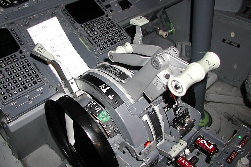
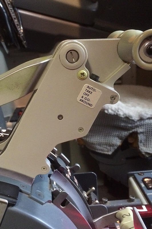
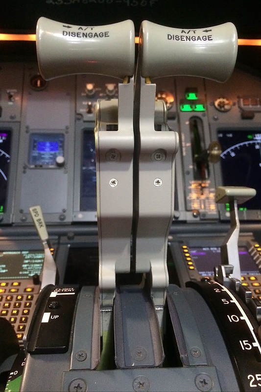
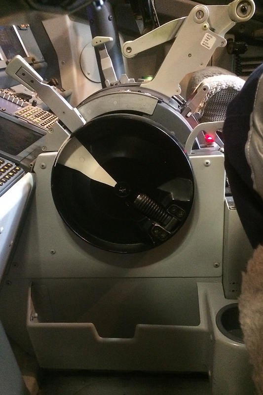
Reverse Thrust Procedure
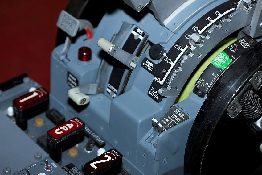
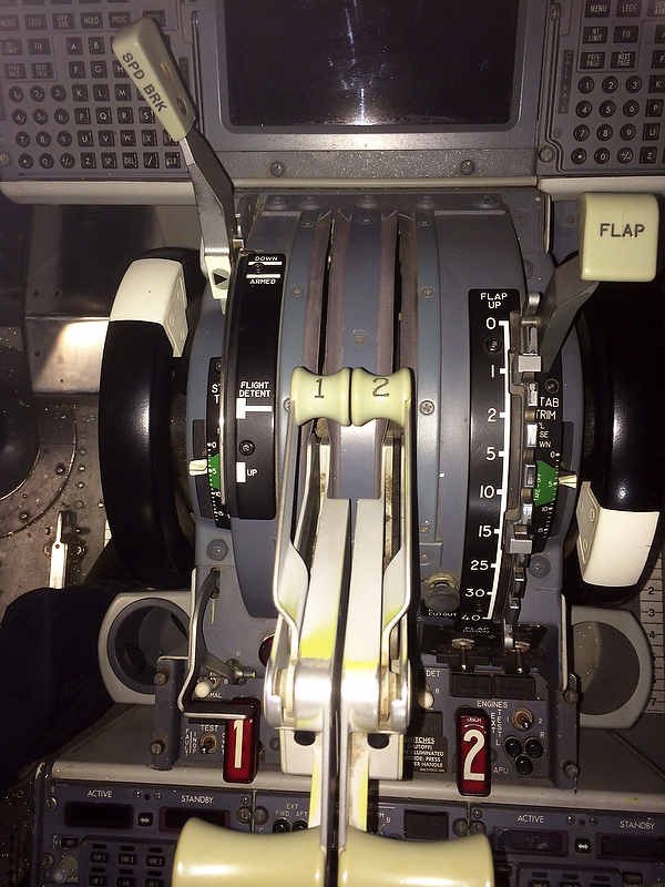
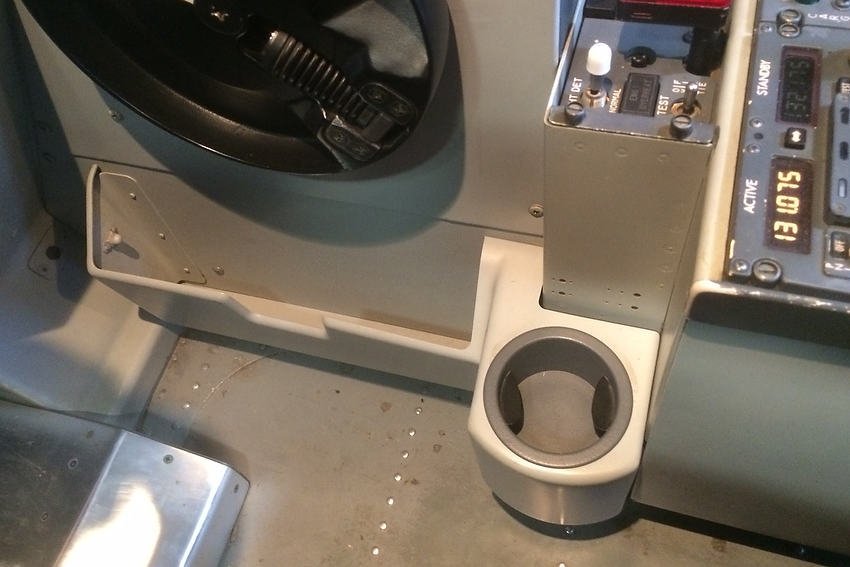
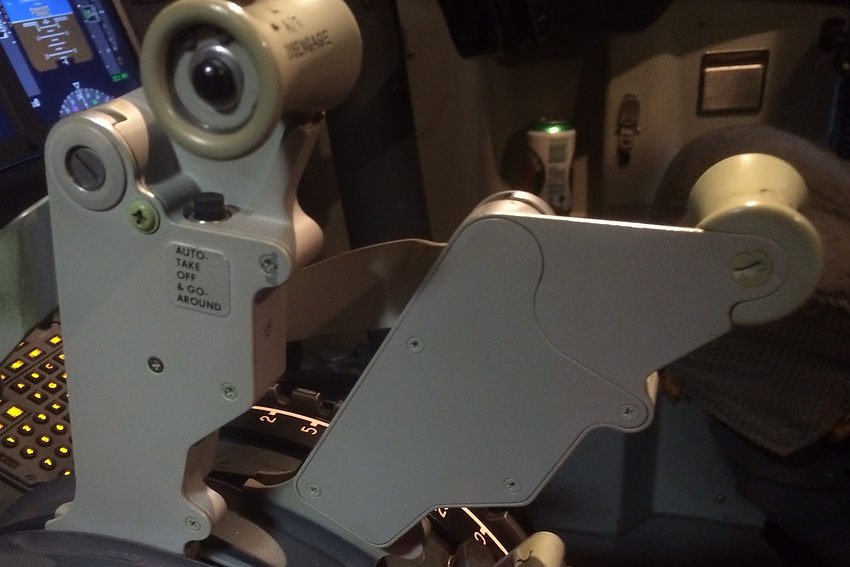
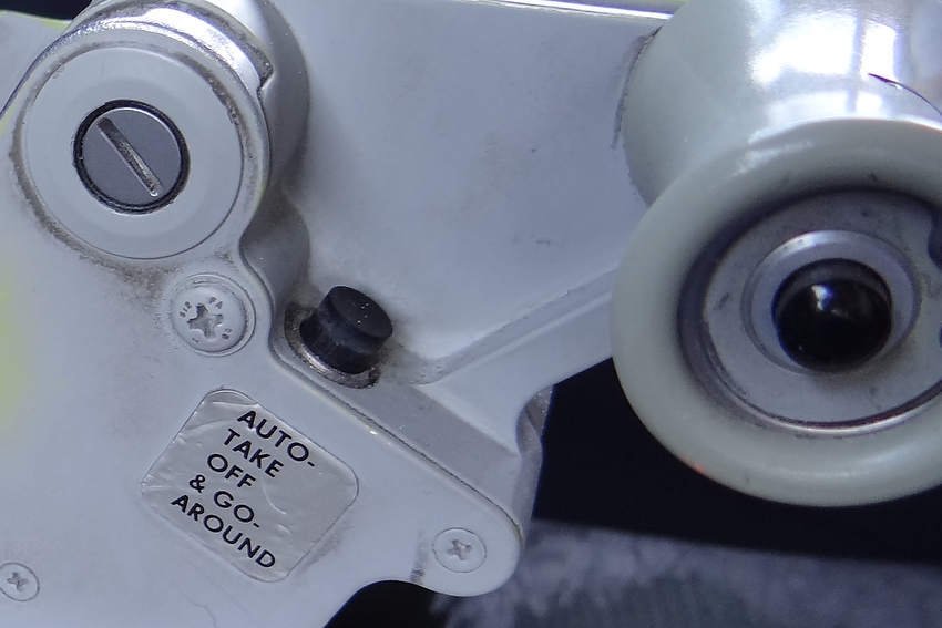
The reverse thrust levers are clearly visible in the stowed position.  OEM throttle quadrant converted for flight simulator use

Pilots tend to be numbers-orientated individuals.  They like concise instructions and do not like ambiguity.  Nor do they like being presented with something that is in ‘shades of grey’ rather than ‘black and white’

When, how, and for how long to deploy the reverse thrust (reversers) falls into the 'grey area'.

In this article, I will endeavour to unravel some of the uncertainties as to when and how to use reverse thrust.  I will also briefly discuss the relationship between the use of the autobrake and reverse thrust.

I am not going to delve deeply into every environmental consideration that needs to be analysed prior to the use of reverse thrust; this information is more than readily available from the Flight Crew Operations Manual (FCOM), Flight Crew Training Manual (FCTM) and other specific airline policy documentation.

Reverse Thrust Basics

Reverse thrust (reversers) is used only for ground operations and is used after touchdown to slow the aircraft;  it is used to reduce the stopping distance, minimise brake temperatures and decrease wear and tear.

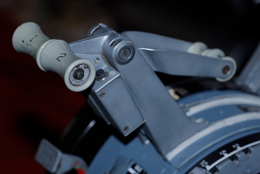
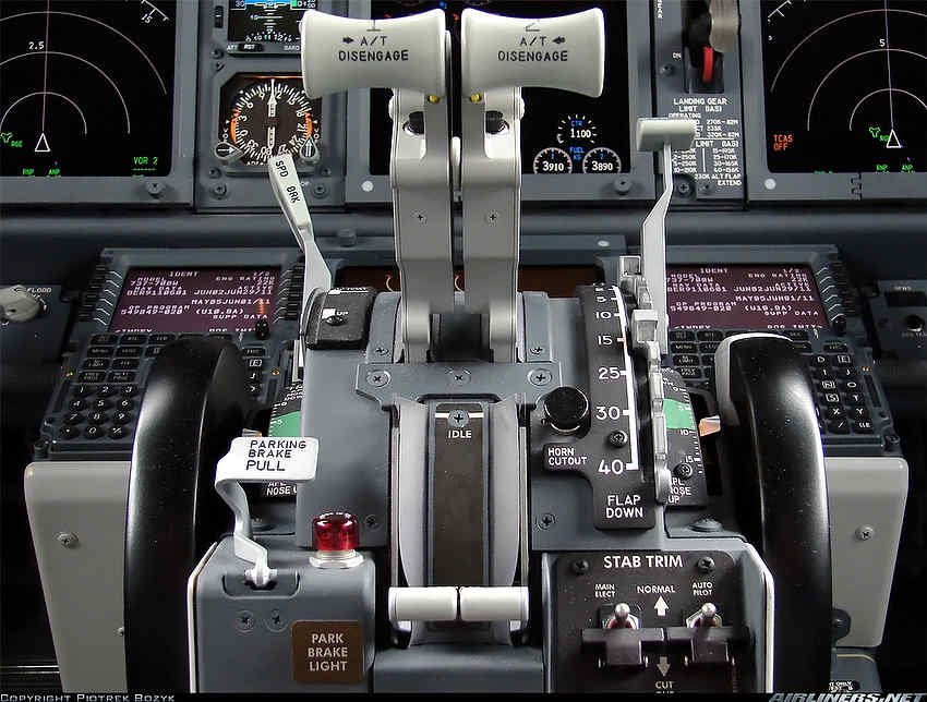
Reverse thrust comprises four détentes and an interlock position, that are engaged by moving the thrust levers from the stowed down position through to the fully up position.  

  1. No reverse thrust (thrust levers are closed / stowed position).

  2. Detent 1 (idle reverse / thrust levers are at first position).

  3. Detent 2 (thrust levers are at second position).

  4. Full maximum reverse thrust (thrust levers are at fully upward position).

Between detent 1 and full maximum reverse thrust there is scope for the thrust levers to be positioned part way; thereby, altering the amount of thrust generated.

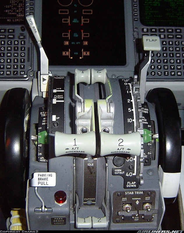
Schematic showing various positions for the thrust reverser levers

The interlock mechanism is felt when the reverse thrust levers are advanced to detent 1. The purpose of the interlock is to restrict movement of the reverse thrust lever until the reverser sleeves have approached the deployed position.

The procedure to use reverse thrust is very straightforward, however, questions arise as to whether to use detent 2 or full maximum reverse thrust, and when to begin reducing thrust and for how long.

Procedure

Following touchdown, without delay, move the reverse thrust levers to the interlock position and hold light pressure until the interlocks release (as the sleeves move rearwards).

For most landings, detent 1 and detent 2 will usually provide adequate reverse thrust (for normal operations).  If additional reverse thrust is needed (wet, slippery or short field landing), full maximum reverse thrust can be selected by raising the thrust levers past detent 2 to full maximum reverse thrust.  

To come out of reverse, the reverse thrust levers are returned to the detent 1 position, the engine allowed to spool down, and the levers then returned to the stow position.

Practically speaking, after touchdown maintain reverse thrust as required up to maximum thrust until the airspeed approaches 60 knots. Reverse thrust is then slowly reduced to detent 1 and then to reverse idle by taxi speed. Wait until the generated reverse thrust has bleed off, then slowly close the reversers and place them in the stow position.

Bringing the reverse thrust levers to detent 1 is important because it prevents engine exhaust re-ingestion and minimises the risk of foreign object debris (FOD) ingestion.  Idle thrust also bleeds off forward thrust from the engines.

The autobrake is disarmed when a safe stop of the aircraft is assured, or when the aircraft reaches taxi speed.

Important Point:

  • If transitioning from using the autobrake to manual braking, use reverse thrust as required until reaching taxi speed and then disarm the autobrake.  

Disarming the autobrake before closing reverse thrust provides a relativity seamless transition which increases passenger comfort (there is no aircraft jolt).

Conditions Required To Engage Reverse Thrust

The reversers can be deployed when either of the following conditions occur:

  1. The radio altimeter senses less than 10 feet altitude;

  2. When the air/ground sensor is in ground mode; and,

  3. When the forward thrust levers are in the idle position.

Until these conditions occur, the movement of the reverse thrust levers is mechanically restricted and the levers cannot be moved into the aft position.

It is important to always deploy reverse thrust as soon as possible following touchdown.  Do not wait for the nose wheel to touch down, but engage reverse thrust when the main wheels are on the runway.  Timely deployment will increase stopping power; thereby, increasing safety and reducing heat build-up in the brake system.  

A study determined that there was roughly a 17 second difference in stopping time when reverse thrust was deployed immediately the landing gear was on the runway as opposed to waiting several seconds for the nose gear to also be on the runway - reverse thrust is most effectual at high airspeeds and its effect decays on a linear scale as forward airspeed decreases.

Important Points:

  • Reverse thrust should always be used with the autobrake, unless the runway is exceptionally long without a possibility of runway overrun (the reason for this will be explained shortly).

  • When closing the reversers, always pause at detent 1.  Monitor the REV thrust output on the Primary Engine Display (center panel) and stow the reversers only after reverse thrust has dissipated.

Call-outs

The pilot monitoring usually makes the following call-outs:

  • ‘60 knots’;

  • ‘Reversers normal’ -  when both REV indications are green;

  • ‘No reverser engine No: 1’ - if no REV indication or colour is amber; or,

  • ‘No reverser engine No: 2’ -  if no REV indication or colour is amber; or,

  • ‘No reversers’ -  if no REV indications or colour is amber.

NOTE:  Annunciators and displays are discussed later in the article.

During landing, the pilot monitoring (PM) should call out 60 knots to advise the pilot flying (PF) in scheduling the reduction of reverse thrust.  

When landings are in conditions that are suboptimal (heavy rain, snow, slush, etc), some operators stipulate that the PM operate and control the reverse thrust .  This enables the PF to concentrate solely on the landing roll out rather than having the extra responsibility of also controlling the reverse thrust.  

This said, although this procedure may lower pilot workload, it can cause problems when the PF is landing on a slippery runway or in marginal crosswind conditions.   At these times, the PF may wish to use the reverse thrust in conjunction with the brakes and there is little time to call out instructions to the PM.

Technical Aspects (basic operation)

Each engine on the Boeing 737 Next Generation is equipped with an hydraulically operated thrust reverser, consisting of left and right translating (moving) sleeves.  Aft movement of the reverser sleeves cause blocker doors to deflect fan discharge air forward, through fixed cascade vanes, producing reverse thrust.  

Hydraulic pressure for the operation of the thrust reversers comes from hydraulic systems A and B, respectively.  If hydraulic system A and/or B fails, alternate operation for the affected thrust reverser is available through the standby hydraulic system.  When the standby hydraulic system is used, the affected thrust reverser deploys and retracts at a slower rate and some thrust symmetry can be anticipated.

When reverse thrust is selected an electro-mechanical lock is released.  This causes the  isolation valve to open which results in the thrust reverser control valve moving to the deploy position, allowing hydraulic pressure to unlock and deploy the reverser system.

The system is designed in such a way that an interlock mechanism restricts movement of the reverse thrust lever until the reverser sleeves are in the deployed position.

Closing the thrust levers past detent 1 to the stow position initiates the command to stow the reverser.  When the lever reaches the full down position, the control valve moves to the stow position allowing hydraulic pressure to stow and lock the reverser sleeves.  After the thrust reverser is stowed, the isolation valve closes and the electro-mechanical lock engages.

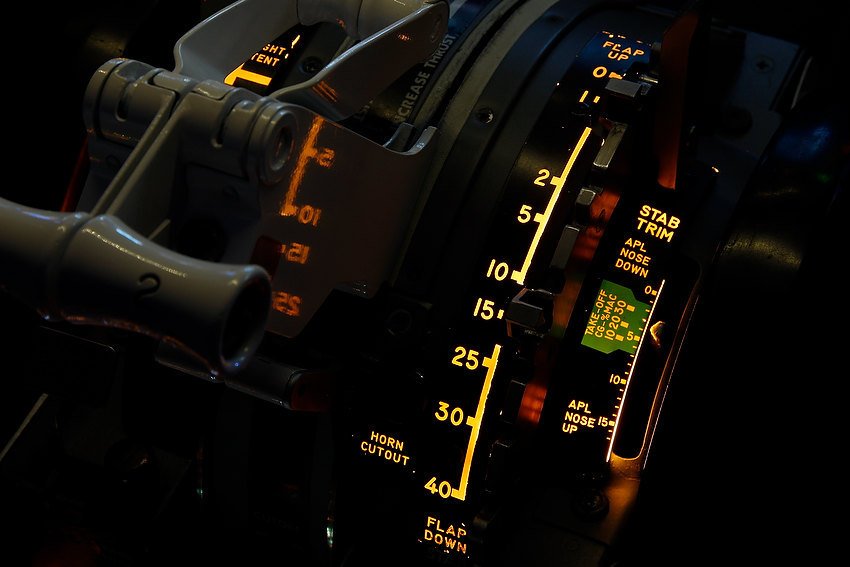
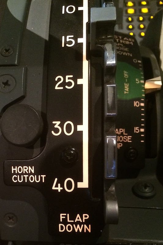
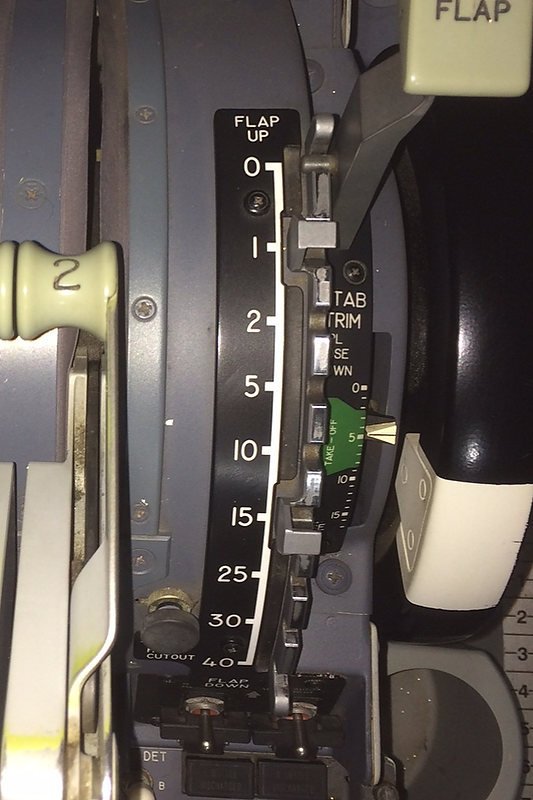
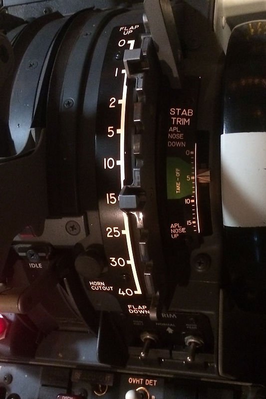
Relationship with Flaps

There is an interesting relationship between the use of reverse thrust and flaps 40.

When the aircraft has flaps 40 extended, the drag is greater requiring a higher %N1 to maintain airspeed. This higher N1 takes longer to spool down when the thrust levers are brought to idle during the flare; this enables more energy to be initially transferred to reverse thrust.

Therefore, during a flaps 40 landing more energy is available to be directed to reverse thrust, as opposed to a flaps 30 landing.

Annunciators and Displays

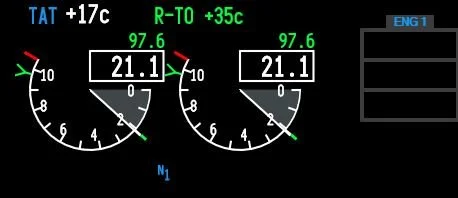
Thrust reverse indicators are displayed in the Primary Engine Display located in the center panel slightly above the No: 1 and No: 2 %N1 indicators.  When reverse thrust is commanded, REV will be displayed initially in amber followed by green dependent upon the position of the thrust reverse levers.

  • Amber:  Thrust reverser has been deployed from the stowed position and both sleeves have travelled ~10-90% to the deployed position.

  • Green:  Thrust reverser has been deployed from the stowed position and both sleeves have travelled greater than 90% to the deployed position.

When either reverser sleeve moves from the stowed position, the amber REV indication annunciator, located on the upper display will illuminate.  As the thrust reverser reaches the deployed position, the REV indication illuminates green and the reverse thrust lever can be raised to detent 2.  

Electronic Engine Control (EEC) panel (AFT overhead). ProSim737 avionics suite virtual display

Additional reverse thrust annunciators are located on the aft overhead panel in the Electronic Engine Control (ECC) panel.  These annunciators are triggered by the retraction of the reverse thrust levers to the stow position.   

The annunciators will illuminate during a normal reverse thrust / stow operation for 10 seconds and then extinguish 10 seconds later when the isolation valve closes.  

A system malfunction has occurred if the reverser (REV) annunciator illuminates at any other time, or illuminates for more than approximately 12 seconds (in the later instance, the master caution and ENG system annunciator will also illuminate).

Possible reasons for a system malfunction are that the isolation valve, thrust reverser control valve, or one or both of the thrust reverser sleeves are not in their correct position.

Autobrake and Reverse Thrust Use (the grey area)

Both the autobrake and timely application of reverse thrust can be used to slow the aircraft, however, both come at a cost.  

Using the autobrake generates considerable heat in the braking system, translating to increased expenditure in maintenance and possible delays in turn around times (waiting for brakes to cool to operational temperature).  Conversely, reverse thrust consumes excess fuel.  Clearly there is a middle point where each will cancel out the other.

The immediate initiation of reverse thrust at main gear touchdown, and use of maximum reverse thrust, enable the autobrake system to reduce brake pressure to the minimum level – this is because the autobrake system senses deceleration and modulates brake pressure accordingly.  Therefore, the proper application of reverse thrust results in reduced braking and less heat generation for a large portion of the landing roll.

Based on this premise, it stands to reason that this is why Boeing recommend to use the autobrake in conjunction with reverse thrust.

Boeing states in the FCTM that: ‘After touchdown, with the thrust levers at idle, rapidly raise the reverse thrust levers up and aft to the interlock position, then to reverse thrust detent 2.  Conditions permitting, limit reverse thrust to detent 2’.

It appears to be Boeing’s intention to use reverse thrust as the major force to stop the aircraft, and as the use of maximum reverse thrust further minimises brake system heating, it would appear to be a preferred choice, despite the FCTM stating detent 2 is the preferred position for normal operations.

The official literature does not satisfactorily address this ‘grey area’   The result being that many 737 pilots use differing techniques when deploying and stowing the reversers.

Various Methods

If you observe how other pilots use the reversers, you will discover that there are several variations that follow the same theme.

1.    A pilot will, when the aircraft passes through 60 knots, close reverse thrust by lowering the reverse thrust levers through detent 1 to the stow position without stopping at detent 1;

2.    Try to locate detent 1 by ‘feel’ resulting in pushing the levers too far towards the stow position, causing forward thrust to unexpectedly occur momentarily;

3.    Deliberately close maximum reverse thrust at the 60 knots by placing the reverse thrust levers into the stow position.

In the above three scenarios, the reverse thrust levers have not been allowed to pause at  the detent 1 position.  Pausing at detent 1 is important as %N1 requires several seconds to reduce to idle thrust after maximum reverse thrust has been used, and it is during this ‘wind down’ period, as the reverse sleeves fully close, that %N1 will transition through 55-60%N1, which is forward thrust.  

By not allowing the reversers to pause momentarily at detent 1, to enable thrust to disparate below 55-60%N1, may cause the aircraft to momentarily accelerate.  This can be rather disconcerting, especially on a short field landing or landing in marginal conditions.

So What Do I do (normal procedure)

  1. At touchdown I engage reverse thrust – either detent 2 or maximum reverse thrust (or part thereof).

  2. Approaching 60 knots I slowly and smoothly retard the reverse thrust levers to detent 1.

  3. I always allow a few seconds at detent 1 to enable %N1 to dissipate.

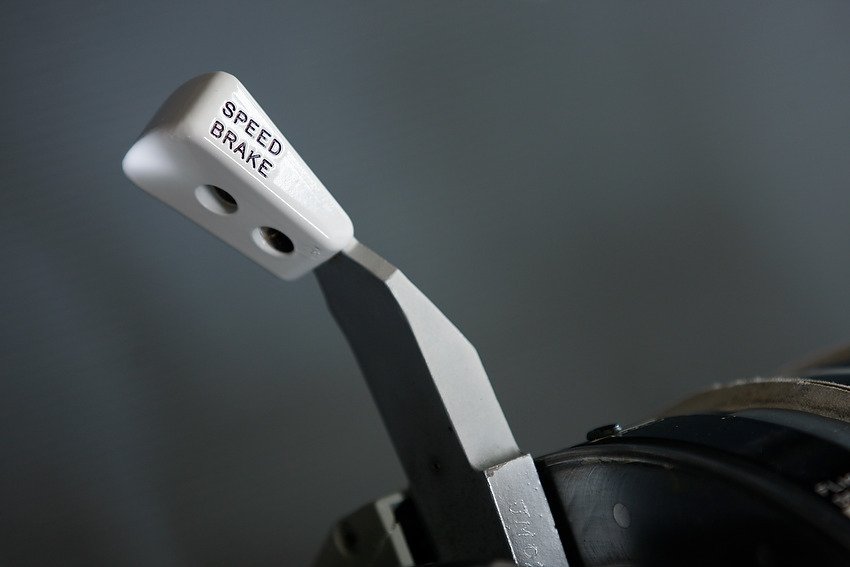
  4.  Approaching taxi speed I disarm the speedbrake and close the reversers.

  • At no time do, unless in an emergency, do I close the reversers suddenly; I always close the reversers smoothly and slowly. This enables %N1 to dissipate gradually.

Final Call

The procedure to deploy reverse thrust is straightforward and very easy to accomplish, and there is little argument that reverse thrust should be used on all, but the longest runways in optimal environmental conditions.   However, there is confusion and often disagreement to when the reversers are deployed, whether maximum reverse thrust should be used, and for how long the reversers should be left in the open position before retraction and stowing.

It is unfortunate that the information written in the Flight Crew Training Manual (FCTM) and Flight Crew Operations Manual (FCOM) does not provide a more objective ‘black and white’ answer to this procedural dilemma.

Video

The below video shows the REV indicators on the Primary Engine Display (when reverse thrust is commanded) and the REVERSE annunciators on the ECC panel (AFT overhead).  Video taken directly from ProSim-AR 737 avionics suite (virtual software).  Video upload to U-Tube rather than VIMEO).


Major Differences Between Classic and Next Generation Throttle Quadrants

There is little mistaking the tell-tale white-coloured handles and skirts of the Next Generation Throttle

The advent of high quality reproduction parts that marry with advanced avionics suites, such as ProSim-AR and Sim Avionics, has led many flight simulator enthusiasts to strive closer to Microsoft’s claim ‘as real as it gets’.

The availability of OEM parts formally used in classic airframes has never been greater, and many enthusiasts are purchasing various parts and converting them to flight simulator use.

The ‘holy grail’ of conversion has always been the Boeing throttle unit, and depending upon individual requirements, many older style throttle units have been retrofitted to appear very similar, if not near-identical, to their Next Generation counterparts.

This article will compare and contrast the major differences between the Boeing 737 classic throttle and the Next Generation throttle.  The word classic is usually used to refer to airframes belonging to the 200, 300, 400 and 500 series.  The Next Generation (NG) refers to the Boeing 600, 700, 800 and 900 series.

Boeing 727-100 throttle quadrant.  Although there are obvious differences in that the 727 has three engines, the overall design and appearance of the quadrant is very similar to its modern counterpart.  Image copyright to Keven Walchle

Historical Context

The throttle quadrant observed in a modern airliner has relatively old roots. 

The fore bearer of the Next Generation throttle was designed in the late 50's and early 60's and was initially used in the Boeing 707 airframe.  As aircraft types evolved, throttle design remained relatively static with similar-designed throttles being used in the Boeing 727, 717 and 737 series aircraft.

The B737-100 made its debut in April 1968, to be followed shortly by the 200 series with a slightly longer fuselage.  During the 1980’s Boeing released the classic series of airframes (300 through to 500 series). 

During this time, the technology altered little and the design of the throttle quadrant reflected the ability of Boeing to reuse existing technology with minimal alterations.  This principle of reuse can save a company millions of dollars in redesign and development costs.

This Goes With That (Compare and Contrast)

The Boeing 737-800 Next Generation is the airframe that many enthusiasts strive to duplicate in a flight simulator.  The reason for this two-fold.  First, the Next Generation is the most umbilicus aircraft flown today, and second, the availability of software that mimics the avionics suite in this aircraft.

However, Next Generation parts are difficult to find, and when found are expensive to procure.  Fortunately for the simulation community, a throttle will function correctly in flight simulator no matter what airframe the throttle originated.

Many of the nuances between a classic and Next Generation throttle quadrant are subtle, and for the most part only the more knowledgeable will notice.  

The more obvious highlights of the Next Generation are the white-coloured thrust lever shrouds, TOGA button assembly, détentes flaps arc, speedbrake lever knob, and the moulded white-coloured side panels and panniers of the lower part of the throttle unit.  Whilst it's possible to alter many of the attributes of a classic throttle to conform with those of an Next Generation, not every part can be easily transformed.  For example, the flaps détentes arc between the classic and Next Generation is very different in design and appearance, and cannot be altered.

TABLE 1: Overview to the main visual differences between the classic and Next Generation throttle quadrants (courtesy Karl Penrose who kindly allowed the use of photographs taken of his 600 series throttle).  Note that there may be other subtle differences, some visual and others in design/operation. 

The table doesn't address the center pedestal as pedestals vary greatly between airframes. 

Retrofit refers to the level of difficulty it is to make the classic throttle appear similar to the Next Generation. Yes meaning it is possible and no, for the most part, meaning it is not possible.


TABLE 1: an overview to the main visual differences between the classic and Next Generation throttle quadrants


1Erratum:  The trim wheels on the Next Generation are slightly smaller in circumference to those of the Classic series.

2  The words 'level of difficulty' is subjective; it depends on numerous factors such as experience and knowledge – neither of which is identical between individuals.

Important Point:

  • By far the most challenging hurdle during a Next Generation refit is the the alteration of the throttle lever shrouds and the TOGA button assembly.

Final Call

The differences between a classic and Next Generation throttles are largely cosmetic with some subtle design and operational differences.  Retrofitting a classic throttle to appear similar to a Next Generation throttle is possible.  However, there will be some things that probably won't be altered, such as the speedbrake lever handle, stab trim indicator tabs, side mouldings, panniers and flap détentes arc.  

This said, the ability to use an OEM throttle, no matter from which airframe, far supersedes any reproduction unit on the market.  OEM throttles are sturdy, robust and well-built.  Unless you do something particularly foolish, you won't damage an OEM throttle.

BELOW:  Two image galleries showing the various differences between the classic and Next Generation throttle quadrants.  Thanks to Karl Penrose who kindly allowed the use of photographs taken of his 600 series throttle.  To stop the slideshow, click the image and navigate by the numbered squares beneath the image.

Boeing 737 Classic Series Throttle Quadrant


Boeing 737 Next Generation Series Throttle Quadrant


  • Updated 21 June 2020.

B737 Center Pedestal Completed and Installed - Flight Testing Begins

oem 737-500 center pedestal and custom panels.  The center pedestal from the 500 series is very similar to that of the next generation

After spending the best part of two weeks wiring the various panels into the center pedestal I am now pleased with the result. 

The center pedestal is from a Boeing 737-500 and is made from fibreglass.  The earlier series two-bay pedestals were made from aluminium.  The three bay pedestal allows much more room inside the pedestal to mount interface cards and house the wiring for the various panels (modules). 

However, as with every positive there often is a drawback.  In this case there are two drawbacks.  The first is a few spare holes must be covered with OEM blanking plates, and the second is the three bay pedestal is considerably wider than a two bay pedestal.  Whilst climbing into the flight deck is easy at the moment, once a shell is fitted, J-Rails will need to be fitted to the seats to allow easy access. 

Space

Taking advantage of the extra internal space of a three bay, I have constructed a small shelf that fits inside the lower section.  The shelf is nothing fancy - a piece of wood that fits securely between the two sides of the pedestal.  Attached to this shelf are bus bars, a Leo Bodnar interface card and a FDS interface card.  A Belkin powered hub also sits on the shelf.  The power supply for the hub resides beneath the platform to the rear ( for easy access).

The bus bars provide power for the various OEM panels and backlighting, while the Leo Bodnar card provides the interface functionality for the two ACP units.  The FDS card is required for operation of the three FDS navigation and communication radios I am currently using.

My aim was to minimise cabling from the pedestal forward to the throttle unit.  The reason for this is the throttle is motorized and moving parts and USB cables do not work well together.  I have two cables that go forward of the pedestal to the computer; one USB cable from the powered Belkin hub and the other the cable required to connect the CP Flight panels.  Both cables have been carefully routed along the inner side of the throttle quadrant so as to not snag on moving internal parts.

Pedestal Colour

The original pedestal was painted Boeing grey which is the correct colour for a B737-500.  The unit was repainted Boeing white to bring it into line with the colour of the B737-800 NG pedestal.

oem 737-500 center pedestal illuminated by 5 volt incandescent bulbs

Backlighting

The backlighting for the throttle quadrant and center pedestal is turned on or off by the panel knob located on the center pedestal.  Power is from a dedicated S-150 5 Volt power supply rated to 30 amps. 

On the Seventh day, GOD created backlighting and the backlighting was said to be good”.

The light plates are mostly aircraft bulbs; however, a few of the panels, such as the phone and EVAC panel, are LEDS and operate on 28 Volts rather than the standard 5 Volts.

Size Does Matter...

It's important when you install the wiring for backlighting that you use the correct gauge (thickness) wire.  Failure to do this will result in a voltage drop (leakage), the wire becoming warm to touch, and the bulbs not glowing at their full intensity.  Further, if you use a very long wire from the power supply you will also notice voltage drop; a larger than normal wire (thickness) will solve this problem.  There is no need to go overboard and for average distances (+-5 meters) standard automotive or a tad thicker wiring is more than suitable to cater to the amp draw from incandescent bulbs.

To determine the amperage draw, you will need to determine how many amps the bulbs are using.  This can be problematic if you're unsure of exactly how many light plates you have.  There are several online calculators that can be googled to help you figure out the amperage draw.  Google "calculation to determine wire thickness for amps".

At the moment, I am not using a dimmer to control the backlighting, although a dimmer maybe installed at a later date.

Minor Problem - Earth Issue

A small problem which took considerable time to solve was an earth issue.  The problem manifested by arcing occurring and the backlighting dimming.  I attempted to solve the problem by adding an earth wire from the pedestal to the aluminium flooring; however, the issue persisted.  The issue eventually was tracked down to an OEM radar panel which was "earthing" out on the aluminum DZUS rails via the DZUS fasteners.  To solve the problem, I sealed the two metal surfaces with tape.

Panels

The panels I am currently using are a mixture of Flight Deck Solutions (FDS), CP Flight, 500 and Next Generation:

  • NAV 1/2 (FDS)

  • M-COM (FDS)

  • ADF 1/2 (CP Flight) - replaced with FDS

  • Light Panel (OEM)

  • Radar Panel (OEM)

  • EVAC Panel (OEM)

  • Phone Panel (OEM)

  • Rudder Trim Panel (CP Flight) - replacd with OEM

  • ATC Transducer Radio (OEM)

  • ACP Panel x 2 (OEM)

  • Fire Suppression Panel (OEM)

In time a ACARS printer will be added and some of the non NG style panels (namely the ACP panels) will be replaced with OEM NG style ACP panels.  The OEM panels installed are fully operational and have been converted to be used with Flight Simulator and ProSim737.  I will discuss the conversion of the panels, in particular the Fire Suppression Panel, in separate journal posts.

The more observant readers will note that I am missing a few of the "obvious" panels, namely the cargo fire door panel and stab trim panel.  Whilst reproduction units are readily available, I'm loathe to purchase them preferring to wait; eventually I'll source OEM panels.  Rome was not built in a day.

Panel Types

If you inspect any number of photographs, it will become apparent that not all aircraft have exactly the same type or number of panels installed to the pedestal.  Obviously, there are the minimum requirements as established by the relevant safety board; however, after this has been satisfied it's at the discretion of the airline to what they order and install (and are willing to pay for...).  It's not uncommon to find pedestals with new and old style panels, incandescent and LED backlighting, colour differences and panels located in different positions.

oem 737-500 center pedestal telephone. although not next generation it completes the pedestal

Telephone Assembly

Purists will note that the telephone is not an NG style telephone and microphone.  I have keep the original B737-500 series telephone and microphone as the pedestal looks a little bare without them attached. 

If at some stage I find a NG communications assembly I'll switch them, but for the time being it will stay as it is.

Flight Testing - Replication

The throttle quadrant and center pedestal are more or less finished.  The next few weeks will be spent testing the unit, it's functionality, and how well it meshes with ProSim737 in various scenarios.  This process always takes an inordinate amount of time as there are many scenarios to examine, test and then replicate. 

Replication is very important as, oddly, sometimes a function will work most times; however, will not work in certain circumstances.  It's important to find these gremlins and fix them before moving onto the next level. 

KIS - Keep It Simple

Although everything is relatively simple in design (OEM part connects to interface card then to ProSim737 software), once you begin to layer functions that are dependent on other functions working correctly, complexity can develop.   It's important to note that the simulator is using over a dozen interface and relay cards, most mounted within the Interface Master Module (IMM) and wired to an assortment of OEM parts configured to operate with ProSim737's avionics suite. 

Wiring the Simulator - Aviation Wire

aircraft wire by the roll

When I first began to work on my simulator, I used whatever wire was available; usually this was automotive electrical wire.  The wire was inexpensive and seemed to do the job; however, there were several shortcomings.  

To carry the appropriate amperage the wire selected was quite large in thickness; therefore, quite inflexible.  This inflexibility resulted in the wire coming loose at connections quite easily.  The thickness also made routing numerous wires quite challenging and at one stage, my simulator looked like a rat’s nest of snaking coloured wires.

After a few connection issues, I began to rethink my approach.  

I have since replaced the automotive wiring with a wire grade more suitable for the purpose.  The wire I use is aviation wire which is available in various gauges (thicknesses) and colour options.  The benefits in using this wire are it:

  • Withstands physical abuse during and after installation 

  • Has a good high and low temperature properties  

  • Is very flexible and small enough to be run in tight places

  • Can be obtained in varying gauges and colours

  • Has a high flex life  

  • Has good out-gassing characteristics

  • Has a fair cold flow property (probably not that important as the simulator is not going to altitude)

The wire can easily be obtained in rolls from supply chain stores or from e-bay.  Enter the following wire reference code into either e-bay or google:  Part Number: 22759-16-22-9; 22 AWG WHITE TEFZEL WIRE.

Please note, this is the wire I use (and many other builders).  There is a wide variety of wire available in the market that is suitable for building, so don't become overly concerned if you've already used a different type of wire.  The main point to remember is that wire is rated to the application and voltages your intending to use.  The wire mentioned is ideal for all wiring requirements of the simulator with the exception of very high voltage requirements.  High voltage requires a wire of lower gauge (thicker wire) to ensure minimal voltage drop over distance. 

The same type of wire as mentioned above can be purchased in differing gauges (thicknesses).  I find 22 gauge is a good overall gauge to use.  Remember that voltage (amps) is rarely being applied to the wire continuously (exception is from power supplies).

jr servo wire security clips

Easy Connect/Disconnect Connectors

Often there is a need to connect a piece of wire to another piece of wire or part and have the ability to be able to disconnect the wires easily and quickly.  For example, often panels must be removed from the center pedestal; having the ability to disconnect wires easily allows complete removal of the item without destroying the attachment wires!

There are dozens of connectors available for joining or extending wires – some are better than others.

I use (where possible and when voltage/amp requirements dictate) JR servo wire security clips.  These little clips allow three wires to enter to either side of the connection, are made from heavy duty plastic, and have a guaranteed clipping mechanism that will not unplug itself.  Search the Internet for JR extension servo clips. 

For applications requiring more than three wires, or higher voltage/amps, I use a high quality terminal block, Canon style plug or a D-Sub plug.  The later two requiring each wire to be very carefully soldered into the appropriate wire reciprocal in the plug.  I also use Mylar quick release plugs for some applications.

All other wires that require a permanent connection are usually soldered together with wire shrink wrap.  Soldering always provides the best connection.

Avoiding Confusion: Acceleration Height, Thrust Reduction Height, Derates, Noise Abatement and the Boeing Quiet Climb System

Thompson B738NG transitioning to Acceleration Height, Manchester, UK

During preparation for takeoff, three similar functions that deal with how the autothrottle calculates N1 thrust can be altered in the CDU: Acceleration Height (AH), Thrust Reduction Height (TRH) and the Quiet Climb System (QCS).  Although there are similarities, each function is used independently of each other. 

Confusion can also occur deciphering the different methods used to alter N1 thrust, such as: Derated Thrust, Assumed Temperature and Derated Thrust Climb.

Acceleration Height (AH)

Acceleration Height is the altitude above ground level (AGL) that a pilot accelerates the aircraft by reducing the aircraft’s pitch, to allow acceleration to a speed safe enough to raise flaps and slats, and then reach the desired climb speed.

Part 23 of Federal Aviation Regulations (USA) dictates that the airplane is able to climb at a certain rate in this configuration up to a safe altitude.

The acceleration height is the altitude that the aircraft transitions from takeoff speed (V2+15/20) to climb out speed.  This altitude is usually between 1000 and 1500 feet, but may be as low as 800 feet; however, can differ due to noise abatement, airline policy, or airport specifics such as obstacles, etc.

The reason for acceleration height is to allow a safety envelope below this altitude should an engine problem develop after rotation; engines are set to maximum thrust, and the plane is pitched for V2 safety speed (V2+15/20).

Acceleration Height is altered in the CDU 'Init/Ref Index/Takeoff Ref Page (lsk4R) Accel HT ---- AGL'

Practical Application

Once the Acceleration Height has been reached, the pilot flying will reduce attitude pitch by pushing the yoke forward to increase speed.  As the speed increases Flaps 5 is retracted.  At this time the speed will need to be increased in the MCP speed window from V2 to climb speed, followed by further flap retraction on schedule. 

Although crews use slightly varying techniques; I find the following holds true for a non-automation climb to 10,000 feet AGL.

  • Set the MCP to V2

  • Fly the Flight Director cues to Acceleration Height (which will be at V2+15/+20).

  • At Acceleration Height, push yoke forward reducing pitch.

  • As forward speed increases you will quickly pass through the schedule for initial flap retraction – retract flaps 5.

  • Dial into the MCP speed window the appropriate 'clean up' speed (reference the top bug on the speed tape of the PFD, usually 210-220 kias).

  • Continue to retract flaps as per schedule.

  • After flaps are retracted, engage automation (if wanted) and increase speed to 250 kias or as indicated by Air Traffic Control.

NOTE:  If the acceleration height has been entered into the CDU, then the Flight Director bars will command the decrease in pitch when the inputted altitude (RA) has been reached - all you do is follow the FD bars.

Thrust Reduction Height (TRH)

The main wear on engines, especially turbine engines, is heat. If you reduce heat, the engine will have greater longevity. This is why takeoff power is often time limited and a height established that thrust is reduced. The difference between takeoff thrust and climb thrust may only be a few percent, but the lowering of EGT reduces heat and extends engine life significantly. 

Thrust Reduction Height (TRH):  The thrust reduction height is where the transition from takeoff to climb thrust takes place.  TRH can be altered in the CDU 'Init/Ref Index/Takeoff Ref Page (lsk1R) Reduction AGL-- AGL'

Figure 1: Thrust Mode Display (TMD).  In this example it is displaying CRZ (cruise). Figure copyright FCOM

The height usually used for thrust reduction, not taking into account noise abatement, can vary; but, 400 feet AGL is the minimum allowed. 

LEFT:  Figure showing Thrust Mode Display (TMD).  In this example it is displaying CRZ (cruise). Figure copyright FCOM.

Once takeoff has occurred, examination of the Thrust Mode Display (TMD) will alert the flight crew to the type of climb that has been choosen.  The TMD will display the acronym TO (takeoff) or R-TO (reduced takeoff thrust) and will alter to CLB (climb) once the Thrust Reduction Height has been reached.

Confusion between Acceleration Height and Thrust Reduction Height

Newcomers are often confused between the two similarly-sounding terms, possibly because they both occur at the interface between takeoff and climb-out.  Simply written:

Acceleration Height is when the nose is to be lowered to allow the aircraft to accelerate. When the aircraft starts accelerating is when the flight crew will retract flaps as per the schedule.  Thrust Reduction Height is when the autothrottle will decrease the engine power to the pre-selected climb thrust; thereby reducing engine wear and tear.  Both may occur simultaneously or at differing heights above ground level.  Both can be configured in the CDU.

Differing Methods to Alter Thrust:  Derated Thrust (CLB-1, CLB-2), Assumed Temperature & Derated Thrust

There are several methods available to flight crews to alter N1 thrust controlled by the autothrottle system, and with the exception of the N1 speed reference knobs on the Main Instrument Panel (MIP), all are accessed via the CDU interface.

Derated Thrust (Derates):  Derate is a term used for derated thrust (or reduced thrust). 

The CDU displays a list of fixed-rate derates which may differ between aircraft, the reason being that each airframe may have a different powered engine.

Derates can be accessed from the N1 Limit Page.

Assumed Temperature:  This method calculates thrust based on a higher than actual air temperature and requires the crew to input into the CDU a higher than normal outside temperature.  This will cause the on-board computer to believe that the temperature is warmer than what it actually is; thereby, reducing N1 thrust.

The outside air temperature can be altered in the N1 Limit Page (lsk1L) or from the Takeoff Ref Page 2/2 (lsk4L).

Derated Thrust Climb (CLB-1 & CLB-2):  Selecting CLB-1 or CLB-2 commands the autothrottle to reduce N1 thrust during any climb phase to a higher altitude.  

Rather than use maximum climb or rate, crews often select CLB-1 which is approximately a 10% derate of climb thrust (climb limit reduced by 3% N1), while  CLB-2 is approximately a 20% derate of climb thrust (climb limit reduced by 6% N1).   Flight crews routinely pre-select a lower than maximum climb thrust before departure.

CLB-1 and CLB-2 can be accessed from the N1 Limit Page. 

The reduced climb thrust setting, no matter which method used, gradually increases to full rated climb thrust by 15,000 feet.

Quiet Climb System (QCS) - Abiding with Noise Abatement Protocols

Boeing has developed the Quiet Climb System, an automated avionics feature for quiet procedures that causes thrust cutback after takeoff.  By reducing and restoring thrust automatically, the system lessens crew workload and results in a consistently less noisy engine footprint, which helps airlines comply with noise abatement restrictions. There are two variables to enter: Altitude reduction and altitude restoration.

During the take-off checklist procedure, the pilot selects the QCS and enters the altitude at which thrust should be reduced.  The thrust reduction altitude is greater or equal to 800 ft AGL and the thrust restored altitude is typically 3000 feet AGL, however the altitudes may alter depending on obstacle clearance and the noise abatement required. 

With the autothrottle system engaged, the QCS reduces engine thrust when the cutback altitude is reached to maintain the optimal climb angle and airspeed. When the airplane reaches the chosen thrust restoration altitude (typically 3,000 ft AGL or as indicated by noise abatement procedures), the QCS restores full climb thrust automatically.  Note that the minimum altitude that the QCS can be set is 800 feet AGL.  This allows the safety envelope dictated by Acceleration Height to remain active.

Multiple Safety Features for Disconnect

The Quiet Climb System incorporates multiple safety features and will continue to operate even with system failures. If a system failure does occur, there are several methods for exiting QCS.  In the most common method, the pilot selects the takeoff/go-around (TOGA) switches on the throttle control levers. The pilot can also take control of the throttles easily by disconnecting the auto throttle and controlling the thrust manually.

The Quiet Climb System, also known as 'cutback' can be accessed from the Takeoff Ref Page (lsk6R).  You will observe the name cutback with on/off.  You can also enter an altitude that you wish the system to restore full thrust.

For completeness, below is a copy of the current Noise Abatement Departure Procedures (NADP). Click image for larger view.


Noise Abatement Departure Procedures (NADP)


Similarity of Terms

When you look at each of the above-mentioned three functions they appear similar in many respects. 

The way I remember them is as follows:

Acceleration Height (AH) is the altitude above ground level (AGL) that is set to ensure take-off speed (V2+15/20) is maintained for safety reasons. 

Thrust Reduction Height (TRH) is the altitude above ground level (AGL) that is set to reduce take-off thrust a few percent to maintain and increase engine life.

The Quiet Climb System (QCS) allows a minimum and maximum altitude to be set in the FMC; thereby, reducing engine power and engine noise.  The restoration altitude is the altitude that full climb power is restored.  The QCS is used only for noise abatement. 

Thrust Reduction Caveat

It must be remembered that any thrust reduction made within the CDU is accumulative.  For example, if you select a lower fixed-rate derate and then select a reduced N1 by the assumed temperature method, the thrust reductions will be added.  It is imperative that the crew actually look at the N1 power settings to ensure they are suitable for the weight of the aircraft, environmental conditions, and length of the runway.  To check and confirm the N1 settings, look at the Thrust Mode Display or the appropiate page in the CDU.

ProSim737

The ProSim737 avionics suite includes the Boeing Quiet Climb System, Thrust Reduction Height, and Acceleration Height. The variables relative to each can be changed in the CDU.

Quality Assurance (QA)

This has been a long post dealing with items that are often confusing in their own right.   Rather than separate the similar topics into individual posts, I thought it easier to deal with them together.

When explaining procedures, I  attempt to keep the writing style simple and easy to understand for a wide range of audiences.  If I have failed, or you discover a mistake, please contact me so this can be rectified.

Acronyms Used

  • AH – Acceleration Height

  • AGL – Above Ground Level

  • CDU – Control Display Unit

  • CLB-1 & CLB-2 – Climb 1/2

  • DERATE – De-rated Thrust

  • FMC – Flight Management Computer

  • LSK1R – Line Select 1 Right (CDU)

  • PFD - Primary Flight Display

  • QCS – Quiet Climb System

  • R-TO – Reduced Takeoff (thrust)

  • RTC – Reduced Takeoff Climb

  • TRH – Thrust Reduction Height

  • TO – Takeoff (thrust)

  • TMD – Thrust Mode Display

Simulator Construction Update - June 2013

Building has been rather slow the last couple of months, although design wise quite a bit has been accomplished.  My main hurdle has been waiting for the replacement throttle quadrant and pedestal to arrive from the United States. 

The throttle has taken considerable time to correctly interface to allow full automation, and the initial brief has been changed to enable the interface cards that the throttle uses to be housed in a dedicated interface module.  The interface module is a trial to determine the feasibility of a modular design.

it's unfortunate, that building cannot continue in earnest until the throttle, pedestal and master module is installed.

I’ve been reliably informed that the new unit is expected to arrive sometime in late August.  There are some surprises in store which I’m sure you will find interesting.

In the meantime, I’ve been busy searching for and purchasing second-hand Boeing parts for some panel additions to the center pedestal and acquiring OEM 737 toggles, switches and bits and pieces for the forward and aft overhead panels.

Construction posts will continue shortly, however, until then I’ll continue to publish posts pertaining to operational procedures for the 737-800.

As with all my posts, if you find a glaringly obvious mistake, please tell me so I can rectify the discrepancy.

Batch Files & Flight-1 Program Launcher - Time Savers

Using Flight Simulator from a flight deck is not as straightforward as many may believe.  Before a flight can commence several programs must be started on two or more computers.  These programs include, but are not limited to; Flight Simulator, ProSim737 (main module, MCP, audio, instructor station, CDU & display modules), FSRAAS, Electronic Flight Bag, WideFS, PM Sounds and so on... 

Although it's not exceptionally time consuming, it does become tiresome using the mouse to activate each program, even if you have shortcuts established on the Microsoft shortcut bar. 

There are numerous methods that can be used to open programs: FSUIPC, WideFS, add on programs such as Flight-1, or a batch file.  However, many virtual pilots lack the necessary skills or confidence to successfully interpret FSUIPC or write a batch file that works the way it's supposed to.

Flight-1 Program Launcher user interface

Flight-1 Program Launcher

Flight-1 Program Launcher is a very easy program that makes starting a flight session exceptionally easy.  In two mouse clicks you can have ALL the required programs opened and ready to use.

Simplicity

The program is standalone, meaning it can reside anywhere on your computer system and does not install into the flight simulator folder directory.  The program interface is very easy to use.

After installation you need to create a list of programs you want the launcher to open.  To do this you click the browse button on the launcher's interface and search for the executable file (.exe) of the target program, and add it to the list and save. 

The Flight-1 Launcher only opens programs, it does not close them

You can select which program starts first, second and so forth....  When you save your preferences a small autostart.cfg file is created in the Flight-1 program folder; this is your preference list (example at left).

Flight-1 launcher - works out of the box

I've been using this nifty program for a few weeks now and have had no issues what-so-ever with it.  It works "out of the box" as designed, and best of all it's shareware!

Flight-1 Program launcher is a free add on available at Flight-1 website.

Writing Your Own Batch File

It's a simple process to bypass the above-mentioned program and write your own batch file.  If you write your own batch file you can also include a batch that closes the programs in addition to opening them.  I've outlined how to make a batch file to close programs.  The same can be done for opening programs but, with different syntax.

  1. Open Notepad ad the editor. Go to "Start" and click on "Accessories." Select "Notepad" from the menu.

  2. Find the file names of the programs you want to close. With the programs running that you want to close, right-click on the task bar and click the "Task Manager" option. Select the "Processes" tab to view a list of file names that are currently running.

  3. Use the "taskkill" command (or whatever command you wish) along with the file names you got from Task Manager. Write a separate command for each file you want to close. Each command line should look like the following example: taskkill /im filename.exe. If one of the programs you are closing is Firefox, the command line would read: taskkill /im firefox.exe.

  4. Save your new application as a .BAT file. Select "Save As" and manually type ".BAT" at the end of the file name you gave to the batch file you just created.

  5. Run the batch file. Double-click on the new application to run it. All the programs you included in the batch file should shut down properly.

A shortcut can then be made to the created file and placed into your shortcut folder.  To edit the batch file, right click the file and select edit.

The syntax required to ensure a batch file works correctly can vary between computer operating systems and your requirements.  I'd recommend a quick search on the Internet to determine the best syntax to use (Google "how to write a opening batch file").

A benefit of using a batch file is that you have to only click one button with your mouse to open or close all the programs required to operate Flight Simulator.

A typical batch file used to open programs is outlined below.  This batch file refers to the main flight simulator computer.

  • @Echo off

  • Echo. Loading software.  ALPHA MAIN COMPUTER (alpha is the name of the computer)

  • start /d "C:\pmSounds" pmSounds.exe

  • TIMEOUT 2

  • start /d "C:\Pro Sim\ProSim737" Prosim737.exe

  • TIMEOUT 9

  • start /d "C:\Pro Sim\ProSimMCP" ProsimMCP.exe

  • TIMEOUT 7

  • start /d "C:\Pro Sim\ProSimAudio" ProsimAudio.exe

  • TIMEOUT 3

  • start /d "C:\FsRaas20" FsRaas20.exe

  • TIMEOUT 2

  • start /d "C:\LOLA" LoLa17.exe

  • TIMEOUT 3

  • start /d "C:\FS10" fsx.exe

Another method of writing the above batch file is outlined below - although the syntax between the batch files is different the outcome is identical.

  • @Echo off

  • Echo. Loading software.  ALPHA MAIN COMPUTER

  • ping -n 2 127.0.0.1 >nul

  • start /d "C:\pmSounds" pmSounds.exe

  • ping -n 2 127.0.0.1 >nul

  • start /d "C:\Pro Sim\ProSim737" Prosim737.exe

  • ping -n 4 127.0.0.1 >nul

  • start /d "C:\Pro Sim\ProSimMCP" ProsimMCP.exe

  • ping -n 2 127.0.0.1 >nul

  • start /d "C:\Pro Sim\ProSimAudio" ProsimAudio.exe

  • ping -n 2 127.0.0.1 >nul

  • start /d "C:\FsRaas20" FsRaas20.exe

  • ping -n 2 127.0.0.1 >nul

  • start /d "C:\LOLA" LoLa17.exe

  • ping -n 2 127.0.0.1 >nul

  • start /d "C:\FS10" fsx.exe

The numeral after TIMEOUT and png -n relates to the number of seconds that must pass before the next program opens. 

For those that are curious, @Echooff triggers a command to prevent the command text from being visible on the screen when the batch file is executed.

Closing Programs - Batch Closure File

The best method to close your simulation dependent programs is to create a closure batch file that closes each program sequentially.

Although it's a simple task to closes programs simultaneously (end processes in Windows Task Manager), there is debate in the computer community to whether killing a program straight-out is a good idea; one school of thought suggests that killing several programs simultaneous may cause problems, if a program is writing files to its file structure and not enough time is allowed for this to be completed.

For this reason, I'm hesitant to close Flight Simulator (or other programs) using a closure batch file without a timeout or delay sequence.  Needless to say, it's an easy process to configure a time delay into a batch file to create a delay before closing each program.

Time-outs

Depending upon your computer specifications some programs may open and close at differing speeds.  If you want to ensure that a program is opened or closed before the next program, then a delay sequence will need to be timed into your batch file.  There are several ways to do this and the syntax varies. 

Below is a typical batch file used to close programs on the main flight simulator computer or server.

  • @Echo off

  • Echo. Closing software.  ALPHA MAIN COMPUTER

  • taskkill /im PMSounds.exe

  • TIMEOUT 3

  • taskkill /im wideclient.exe

  • TIMEOUT 5

  • taskkill /im ProSimAudio.exe

  • TIMEOUT 3

  • taskkill /im ProsimMCP.exe

  • TIMEOUT 5

  • taskkill /im Prosim737.exe

  • TIMEOUT 10

  • taskkill /im FsRaas20.exe

  • TIMEOUT 5

  • taskkill /im LoLa17.exe

  • TIMEOUT 5

  • taskkill /im FSRealTime.exe

  • TIMEOUT 2

  • taskkill /im fsx.exe

The timeout command is used to trigger a delay between the closure of the programs, ensuring that any read/write requirements are able to occur before the next program closes.  The numeral denotes seconds.  The timeout settings on this file are a little long and probably should be shortened.

IM specifies the image name of the process to be terminated.  For example, PMSounds.exe

You will note I've used Taskkill to close the programs.  Taskkill will cause the program to terminate gracefully (1), asking for confirmation if there are unsaved changes. To forcefully kill the same process, add the /F option to the command line. Be careful with the /F option as it will terminate all processes without confirmation or saving of data.

(1)  Information regarding Taskkill obtained from several Internet resources.

I am NOT a computer technician.  The batch files I created for my simulator set-up have worked flawlessly and I am confident, with the correct syntax for your system, they will also work for you. 

If you are like me and tire of opening and closing several programs with a mouse, then try a batch file, or at the very least download and trial the Flight-1 Program Launcher.

B737 Blanking Plates - Cover That Unsightly Gap

OEM blanking plates complete with DZUS fasteners recently removed from a scrapped 737 - the dirt and dust is still on them!  Note three differing sizes - 1" 2" and 4"

No matter what style of simulator you are using or have constructed, you will most likely have a center pedestal installed.  The pedestal will be either a two-bay or three-bay type and be a genuine aviation part incorporating DZUS fastener rails, or a reproduction unit manufactured from wood, metal or plastic.

The two-bay pedestals, once allotted the standard Boeing avionics suite, usually have no  space remaining for additional avionics; however, the three-bay pedestals have substantially more 'real estate' and often gaps are remaining that are not filled with avionics.  Most enthusiasts either leave this space open which looks very unsightly, or manufacture their own plate to cover the gap.

OEM Blanking Plates

Why not use the real part….  

Boeing produces several blanking plates in varying sizes to be used to cover any 'gaps' not used in the center pedestal, forward and aft overhead panel, or Main Instrument Panel (MIP).  These plates are machine-grade light weight steel (or aluminum), are painted Boeing grey, and incorporate the required number of DZUS fasteners for attachment to DZUS rails.  The plates come in a variety of sizes with 1 inch, 2 inch, and 4 inch being the norm.

These plates are inexpensive and usually retail between $5.00 - $20.00 USD, and not only fulfill the task of covering an unsightly gap, but are easy to install, come pre-cut, are painted the right colour, and usually have DZUS fasteners attached to them. 

If not using real DZUS rails and your pedestal in made from wood or plastic, then it’s relatively easy to remove the fasteners and replace them with reproduction screw-type DZUS available from GLB Products.

Most aircraft wrecking yards carry these plates, as airlines regularly purchase them.  Failing this E-Bay often has blanking plates for sale. 

Magnetic Declination - FS9, FSX, P3d and MSFS-2020

Flight simulator whether it be FS9 or FSX, is quite long in the tooth as far as software programs go.  These programs was released several years ago and during this time span there have been many improvements in computer technology and in real world flying procedures.  When released, FS9 and FSX contained the latest navigational data, including the correct declination, VOR, and ILS radio frequencies; however, these are now out of date with real world counterparts.  

Magnetic Declination

Magnetic declination has a very important influence on air navigation, beginning with the use of the standard compass and sectional flight chart.  Similarly, radio navigation aids on the ground, such as VORs use magnetic variation to ensure reliable and accurate in-plane navigation.  The direction of the runway also relies heavily on magnetic variation and runway directions often require updating to ensure that ILS systems operate as designed. 

Simply explained, magnetic declination is the difference between true north and magnetic north and the value changes each year.  Flight Simulator is referring to a value that was accurate when the software was developed but has changed considerably in the ten years plus since the program was released. 

I realized a problem existed when I noticed that the direction of the runway did not align correctly with the latest navigational database installed into ProSim737 (Navigraph).   The CDU continually issued advisory warnings informing me that the runway direction and database were not identical.  Although it's possible to ignore the warning advisory, it becomes tiresome to continually reset the CDU  whilst in the more demanding phase of approach and landing.

Updating Magnetic Variation

Screen grab of program interface

Updating this data is easy thanks to Herve Sors.   Herve has developed a free stand alone program that easily and quickly updates the magnetic variation in either FS9 or FSX whilst also providing the opportunity to rectify out of date and changed runway directions.  The information can be updated globally or by country region, and if necessary you can revert back to the old data.

Without going into unnecessary detail, the program decompresses, corrects, and compiles the necessary information within the .BGL files, located in the scenery folder of flight simulator; it's in this folder that the various navaids are recorded.

Do I need To Update ?

The ability of simulator to accurately simulate navigation is only as good as the navigational database installed.  Think of the database as a street directory or telephone book - do you want to search the directory for out-of-date information?  The update is a very simple process and takes but a few minutes and it's strongly recommended.

By updating virtual pilots will benefit at the very least from:

  • All VOR and NDB data will be up-to-date, allowing chart usage to easier with current charts.

  • Correct calibration of magnetic declination of navaids that provide an azimuth information (VOR/VORDME/NDB) that will be greatly improved matching the "as real as it gets" experience while navigating (tracking navaid radials will be as it is indicated on charts).

  • ILS data (for those that are corrected, Europe only at this time) will be correct.

To download the required software (FSX World NavAids 4.32 & MagVar Data) and investigate Herve's various other programs, navigate directly to his website at AeroSors NavAids.

The software also updates the database for Prepar3D and MSFS-2020.

Sheepskin Seat Cover added to Weber Captain-side Seat

sheepskin seat cover added to oem weber seat

Sometime ago I acquired a pair of Weber pilot seats which came with the correct Boeing diamond-pattern, grey honeycomb seat covers.  However, one of the seat covers was slightly damaged.  The lower cover was also a tad on the small side and kept popping off the rear section of the lower cushion when you sat on it.  Not a major problem, but it was slowly becoming irritating having to repeatedly attach the cover back on the cushion.

The small size was probably caused by the previous owner washing the seat cover;  Boeing covers are renowned to shrink substantially when washed in hot water!  To rectify these minor problems, I decided to have the captain’s side upgraded to a sheepskin seat cover.

A friend of mine has access to high quality Boeing-style sheepskins and being a wizard at sewing, agreed to retrofit the cover for me.

It should be noted that sheepskin covers are not attached to the seat like you would do on an automobile.  Rather, the sheepskin is sewn directly onto the existing fabric of the original seat cover.  Colour varies somewhat depending upon the manufacturer awarded the Boeing contract, but in general they are grey to tan in colour.

I think you will agree, that the final outcome looks, and certainly feels, much better than the original damaged and too small seat cover.