Boeing Chart (Map) Lights - B737NG and Classic B737 Types

Chart lights removed from a Boeing 737-800 NG airframe.  Colour, appearance and design is different to the the older style lights used in the classic airframes

Chart lights (also called map lights) are attached adjacent to the overhead panel and are used to illuminate, in particular, the chart holders attached to the yoke during night time operations. There are two lights, one on the Captain-side and the other on the First Officer-side.

The light from the unit can be focused from a wide angle to a narrow beam by twisting the focus ring at the front of the light.  Each light can also be swiveled and moved vertically to position the light beam in a particular place on the flight deck (for example, chart plates).

The switches (knobs) that turn the light on and off are located on the sidewalls of the Captain and First Officer side of the flight deck.  The light can be dimmed if necessary by rotating the knob.

The chart lights are mounted near each the eyebrow windows.

Chart light removed from a Boeing 737-400 airframe.  The light has a differing focus ring, appearance and colour to the NG style (click to enlarge).  I believe this style of chart light is also used on the B747 aircraft

Two Styles (Classic and NG)

To my knowledge, there are two styles of chart light that have been used in the Boeing 737. The fatter style used in the classic series airframes and the more slender style used in the in the Next Generation airframes.  I have little doubt that there may also be small differences between light manufacturers.

The main aesthetic difference between the older 737 classic airframe chart lights and the newer Next Generation style is that the older lights are squatter and a little fatter in shape; the Next Generation is longer, more slender-looking and has a smaller footprint.

Chart light showing reflector dish on inner side of end cap.  This style is the older light type used in the 737 classic airframes

Other differences are internal and relate to how the light is focused on the lens and the physical shape of the focus rung used to alter the angle of light coverage.

Ingenious Design

Both style lights have an ingenious design to allow the light to be focused.   Removing the rear plate of from the older style light reveals the inner side to be a circular reflector dish (see image) which evenly distributes the throw of light when the unit is set to wide angle. 

The newer Next Generation style lights use an aperture blade which either enlarges or contracts as the focus ring is turned.  This design is identical to how a camera aperture works.

Both styles can use either a 12 or 28 Volt bulb; the later will generate a brighter light.  Connection is direct to the power supply (12 or 28 Volt).  An interface card is not required.

The NG style chart light.  A blade aperture controls the amount of light that is reflected onto the thick lens glass

Original Equipment Manufacturer (OEM)

Put bluntly, you cannot achieve a more realistic end product than when using a real aviation part.  Genuine parts, although at times difficult to find, are built to last; if they can withstand the continue abuse of pilots in a flight deck then they are more than adequate for home simulation use. 

It's true that while some parts appear used with faded and missing paint, they can easily be cleaned up with a fresh coat of paint.  Personally, I prefer the worn-appearance.

OEM Boeing 737 Stick Shaker - Interfacing and Operation

OEM 737 stick shaker installed to Captain-side column.  The lower section of device is what vibrates

The stick shaker is standard on all Boeing series aircraft; the Next Generation having two units (Captain and First Officer) and the earlier classic series having one unit.  The stick shaker is mounted directly to the control column and is designed to vibrate if air speed degrades to stall speed.  The Stick shaker I am using is manufactured by a company in New York. It is powered by 28 Volts (27.5 Volts to be exact).  

Configuration

Configuration of the stick shaker is a relatively easy task.  The electrical cable from the device is connected to 28 Volts, or if this is not available 12 Volts;  12 Volts still produces enough power for the shaker to vibrate, although the intensity is not as great as if the unit was connected to 28 Volts. 

To allow Flight Simulator to connect to the stick shaker, a relay card is required such as a Phidget 0/4/4 relay card.  A USB cable then connects from the card to the computer.  The stick shaker will vibrate when variables that relate to low air speed are met.  The variables are determined by the flight avionics software (ProSim737 or Sim Avionics).

Phidget 0/0/4 relay card showing the main positive wire (red wire) cut with each end inserted into the correct terminals of the relay card

Interfacing and Wiring

The Phidget 0/0/4 relay card is mounted in-line between the 28 Volt power supply and the stick shaker.    Either of the two wires (+-) from the power supply can be cut to install the in-line relay; however, only one wire is cut; the other remaining unbroken from the power supply to the stick shaker.

The 0/0/4 relay card has four relays of which one is required.  Each relay has three terminals: normally open (NO), common (C) and normally closed (NC).  For the stick shaker the common and normally open terminals are used.

Carefully cut one of the two wires leading from the 28 Volt power supply.  Insert the wire coming directly from the power supply into the terminal marked common (1C, 2C, 3C or 4C).  The other end of the cut wire, which comes from the stick shaker is inserted into the terminal marked NO (normally open) of the same terminal.

If the wires have been inserted into the correct terminal of the relay card, the circuit will be complete only when the parameters established within the flight avionics software are valid.  At all other times the relay will break the circuit by not allowing the power to reach the stick shaker. If you have made a mistake, the stick shaker will vibrate continuously.

Protection

When connecting the stick shaker, it is a good idea to include a diode to protect your computer from any magnetic return signal should the relay fail.  A return signal to the computer may cause problems with the computer, and in it worse instance allow 28 volts to surge into the computer destroying your mother board. 

Positive and negative wires from the stick shaker enter the terminal block on the right.  A diode is placed on the corresponding end of the terminal block prior to the two wires running to the relay (not shown)

A high-end relay, such as a Phidget 0/0/4 relay should not fail, and if it does it should fail in the closed position.  However, if 'Murphy' or 'Sod' is your First Officer then it is better to be safe than sorry, so best install a diode.

A diode is an inexpensive and very simple device that behaves in a similar way to a black hole (astronomy).  In a black hole all matter is sucked into the hole and no matter, including light leaves the hole; it is one way trap.  A diode behaves in exactly the same way.  If a failure of the relay occurs, any power that is being transmitted through the wire from the stick shaker (28 volts) will enter the diode and be trapped.  No current will leave the diode.

Three 6 cm diodes.  The silver spirals indicate the positive side (red tape) while the opposite end is the negative (white tape).  Diodes come in an array of differing shapes, sizes and trapping capacities

The heavy duty diode should be placed in parallel between the stick shaker and the relay card.  It is best to try and place the diode as close to the stick shaker as possible.  Place the positive side of the diode (usually appropriately marked) on the positive side.  The other end of the diode place on the negative side.  If you use a terminal block it is very easy to connect a diode into the circuit (see photograph).

Incorrect Wiring

Do not become concerned if you have connected the wire to the wrong terminal - the stick shaker will not be destroyed.  It will be obvious if you have inserted the wires incorrectly, as the stick shaker will operate continuously as it has unbroken power.

I was debating to re-paint the stick shaker, however, decided to keep it as it is.  I like the used look rather than the pristine 'never been there' look.

Although the stick shaker is not essential, it’s often the smaller things and attention to detail which help bring the simulator to the next level.  I am using OEM control columns and adding a stick shaker enhances the immersion.

OEM and Reproduction

When an OEM stick shaker vibrates, especially when you are not expecting it, the vibrations startle you . The yoke vibrates and the noise of the vibrations is quite loud. In contrast, reproduction stick shakers generate lower vibrations and noise.

Acronyms 

  • OEM - Original Equipment Manufacture (real aviation parts)

BELOW:  A short video demonstrating the noise and vibration made to the control column and yoke by the stick shaker when approaching stall speed.


Genuine B737 Forward & Aft Overhead Panels Purchased

For some time I’ve been debating whether to use a reproduction or OEM forward and aft overhead panel.  I have been favouring an OEM panel as this is in line with using genuine parts in the simulator, however, the overhead is a complicated piece of kit and ensuring complete functionality would be a challenge.

RIGHT:  Forward Overhead Panel.  The centre panels will be replaced to conform to a 737 Next Generation.  Panel was removed from a United Airlines 737-300 aircraft.

Certainly, using an overhead panel made by Flight Deck Solutions (FDS) is an easier option, however, despite their reproduction panels being high quality, there are discernible differences between reproduction and OEM panels.  

OEM 737 Overhead Panel Purchased

My decision was made for me when I was told a forward and aft overhead had become available from a recent 737 pull down.  Rather than remain indecisive, I thought I’d jump in “boots and all” and purchase it.  The two overhead panels have come from B737-300 and include the frames, DZUS rails, center panels, Cole engine starter switches, landing gear toggles and various other knobs and toggles.

I’m impressed at the condition of the panels; usually when panels are removed from an aircraft in a tear down yard there is little care given, and the frames become scratched, dented, or damaged in some way.  The frames I have purchased appear to be in relatively good condition.  

Cole Switches

I was fortunate that the two engine starter switches (Cole switches) were included.  These switches are made to exacting requirements and use a solenoid mechanism. 

LEFT:  Difficult to find operating Cole switches are used on all Boeing airframes from the 727 through to the Next Generation.

Purchasing Cole switches individually is quite expensive, so I'm pleased they were not striped from the overhead.

Panels and Backlighting

When I began to construct the simulator in mid 2011, I was adamant that backlighting should match that of the MIP, throttle quadrant and center pedestal.  I believe it was around 2006 that Boeing began to replace bulbs in favour of LEDS.  Certainly, the latest made Boeing uses LEDS. Therefore, my opinion has changed and I am happy to mix bulbs and LEDS (within reason)

The use of bulbs in the overhead uses a lot of power and generates considerable heat; using LEDS minimises power consumption and produces less heat.  If the LEDS are installed correctly, their resultant light is very similar to that of bulbs, and the brightness observed in the real aircraft.

Ultimately the back lighting will be dependent on whether I decide to use older style genuine Boeing panels or reproduction panels.

Realism & Authenticity - How Far Do You Go

Some flight deck builders go to extremes to ensure their flight decks replicate exactly what is seen in the real aircraf,t and while this is admirable, this is not the route I am 'religiously' going to travel.  There has to be compromise between replicating something exactly and having a functional flight simulator.

The end product will  be a combination of genuine (OEM) and reproduction parts - mostly OEM.

Furthermore, serious thought must also be given to how the overhead is going to be installed to the simulator; whether it be to a shell, such as produced by FDS or to a custom-made roll cage assembly.

I'll keep the Blog updated as parts are found and the overhead is developed.

  • Unfortunately I do not have any high quality pictures. These images were supplied by the vendor. Currently the overhead is still located in the US.  In time better quality images will be uploaded.

B737-800 Cabin Phone System Panel - Center Pedestal

oem 737-800 cabin phone panel: Panel has three push buttons with backlighting and legends, and one toggle button

I recently acquired an avionics panel that is a little different to the norm.  The panel was acquired from a company that was responsible for altering the on-board communication system for 50 Boeing 737-800 jetliners; the aircraft were being refitted with global communication equipment.  The upside for me was that the panels were being decommissioned and were not required by the supplier.

Late model 737 Next Generation panels are uncommon to find; therefore, it is interesting to observe the differences between the older style classic panels regularly seen on e-bay, and a newer style panel. 

The first thing that comes to mind, other than condition, is the lack of a rear box assembly on this panel.  Instead of an aluminum box, the wiring is protected by a stainless bracket assembly.  The wiring harness is also more refined and neater looking, while the backlighting, rather than using 5 Volt bulbs uses LED technology.

oem 737-800 cabin phone panel. note the crispness of the legend

LED Technology

Most people are familiar with the 5 volt incandescent bulbs used to illuminate the light panels in Boeing aircraft - the bulbs produce a soft yellow-orange hue.  The colour temperature is in stark contrast to the white hue produced by LED technology. 

I believe that airframes post 2006 utilise LED technology.  Notwithstanding this, until older airframes are phased out, panel lighting will be a mixture of incandescent and LED lighting, or a combination thereof. 

Matching Colour Hue

Attempting to match the backlighting colour hue, especially in the center pedestal and overhead panels has always been a challenge for flight deck builders, especially when using an assortment of older style OEM panels and panels made by differing companies (FDS, CP Flight, Open Cockpits, SimWorld, etc).  

Wiring is very neat and the panel does not utilise the more commonly found aluminum box structure

What many virtual pilots forget, is that the only purpose for an airlines’ existence is to generate income and a profit for the company. Pilots on the other hand are more concerned with flying the aircraft. 

There is very little thought as to whether a panel's backlighting is the same colour hue throughout all the panels.  If and when a panel needs to be replaced, a technician’s only concern is getting a workable and certified instrument fitted into the aircraft as quickly as possible. 

it is not unrealistic to have a few LED panels scattered amongst older bulb illuminated panels

Cabin Phone System Panel - What Works

Although there is no obvious use for this panel in the simulator, it is a good-looking panel that improves the overall aesthetics - it fills a 'gap' in the three-bay center pedestal.  The buttons do function and when depressed change colour and provide different cautionss.  Lifting the red cover and pushing the toggle to test causes the third button to illuminate 'smoke' in orange.

Although the panel has not been connected to an interface card, it is an easy process to connect a PoKeys or Leo Bodnar interface card to the Canon plug. ProSim737, nor Sim Avionics include functionality with this panel.

Replacement OEM 737-500 Throttle & Center Pedestal - Conversion to NG Style

737-300 throttle quadrant with old style paddle-style stab trim levers

The last few months have seen quite a bit of activity regarding the throttle quadrant and center pedestal, which has culminated in me selling my former 737-300 series throttle quadrant and pedestal and replacing it with an another unit from a late series 737-500 aircraft.

Brief Recap

In late 2012, I decided to convert the 737-300 throttle to full automation.  A dilemma I faced was whether to keep the throttle unit as a 300 series throttle with the attached two-bay pedestal, or do a full conversion to make it similar to the Next Generation. 

After careful consideration, it was decided convert the throttle quadrant.so it appeared as close as possible to the Next Generation.

Stab Trim Switches

One of the biggest differences, apart from thrust lever handles, between early model throttle units and the Next Generation units is the stab trim cut out switches.  On the earlier 300 series units, the switches are paddle / lever style switches while the Next Generation uses toggles and T-Locks.  T-Locks are a safety feature and sit beneath the toggle switches and are spring loaded; the pilot must push down the T-Lock to activate the toggle.  

To convert the trim switches requires cutting out the old switches and fitting new reproduction Next Generation switches.  This is a major task requiring precision work.  Although reproduction switches can be made, the reproduction T-Locks don't operate as the real T-Locks should.  I did search for some genuine T-Locks and toggles, however, my search was fruitless as these parts appear to be reused by airlines (or recycled).

Replacement 500 Series Throttle Quadrant & Three-Bay Center Pedestal

A friend of mine informed me that a late model 737-500 throttle quadrant was for sale.  This unit was in better shape than my existing throttle, included the genuine Next Generation style stab trim switches complete with T-Locks, and also had a three-bay center pedestal.  It appears provenance was shining on me as the new throttle appeared for sale a day before the stab trim switches were about to be removed (with a metal cutter...)

The throttle and center pedestal were purchased (you only live once!) and the 300 series throttle sold to an enthusiast in Sweden.

Next Generation Conversion

To bring an earlier style throttle and center pedestal to appear similar to a Next Generation throttle quadrant requires, at a minimum:

  • Attachment of a Next Generation style throttle lever shroud to existing aluminium levers;

  • Removal of TOGA buttons and relocation to bring design in-line with a Next Generation (the buttons are identical, but the housing is different);

  • Possible replacement of the stab trim switches;

  • Painting of throttle housing and center pedestal from Boeing grey to Boeing white; and,

  • Painting of all throttle knobs from Boeing grey to Boeing white.

The biggest hurdle is usually replacing the trim stab switches, however, as these are already present on the new throttle, and are the Next Generation, considerable time and expense was saved in not having to replace them.

Main Differences - Next Generation & Classic

The Boeing airframe that most people associate with today begins with the 737-200 and ends with the 737 Next Generation.  In between we have the classics which refer to the 737-300, 400 & 500 series airframes. The 737 Next Generation series includes the 737-600, 700, 800 & 900 series airframes.

The main differences between a classic and Next Generation throttle quadrant are:

  • The stab trim switches are slightly different; the classics having two flat levers while the Next Generation has toggle-style buttons with T-locks;

  • The throttle thrust lever handles; the classics are bare aluminium and the Next Generation is white aluminium that is ergonomically-shaped.  The TO/GA buttons are also positioned in a different place on the Next Generation.  The knobs (handles) on the levers are also coloured white rather than off-grey;

  • The method that the throttle thrust levers move during automation.  The classics move both thrust levers together when auto throttle is engaged.  The Next Generation moves each lever individually in what often is termed the throttle dance (this is due to the computerised fuel saving measures incorporated in the Next Generation);

  • The spacing (increments) between each flap lever position is identical in the Next Generation, but is different in the earlier series throttles;

  • The center pedestal in the classics is either a two-bay pedestal (early 300 series and before), but more likely a three-bay pedestal.  The Next Generation always has a three-bay pedestal.  Base materials for the center pedestal are also different - aluminium verses a plastic composite material;

  • The speedbrake knob is very slightly more elongated on the Next Generation unit; and,

  • The telephone, circuit breakers and mike assembly differ in type and location

Next Generation Skirt - Thrust Levers

Boeing when they designed the Next Generation style throttle didn’t design everything from new; they added to existing technology.  All Next Generation throttles utilise thrust levers which are identical to those of earlier units.  

Boeing designed a shroud or skirt that attaches over the existing thrust levers encapsulating the older thrust levers and sandwiching them between two Next Generation pieces.  The assembly is made from aluminium and is painted white.

The TO/GA buttons are located in a different position on the Next Generation units, although the buttons used are identical.

To alter the position of the TO/GA buttons you must detach  the small aluminium box from the 300 series thrust levers, remove the TO/GA buttons, and then re-solder the buttons in the appropriate location on the new unit.

I did not make the Next Generation skirt for the thrust levers, but rather had fabricated, from design specifications, a reproduction skirt.  The skirt is produced from aluminium and replicates the dimensions of the Boeing part.

Time-line, Functionality and Conversion

The throttle is initially being converted in the United States.  The advanced work (automation) will be done by a good friend in California, and then I will follow on with more mundane tasks.

The replacement unit will feature several improvements which will allow: full motorized functionality, full speed brake capability, accurate trim tab movement, alternate trim wheel spin speeds, correct park brake release, trim wheel braking and several other features. 

I want the functionality of the throttle to be as close as possible to that found in the real aircraft; therefore, the methods used to ensure this functionality will be slightly different from the norm.

When the throttle is fully functional and tested, I'll publish a post providing further information and detailed photographs of the various functions.

It is hoped everything will be completed, and the throttle and pedestal installed by late May 2013.  The next month or so will be quite exciting.

Two-bay Pedestal Will Be Missed

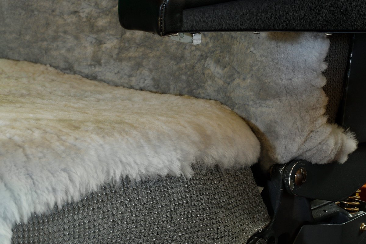
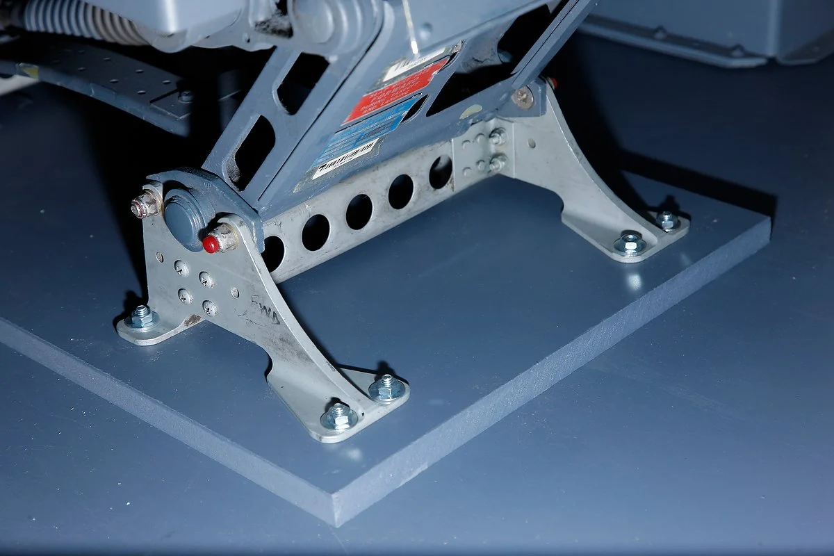
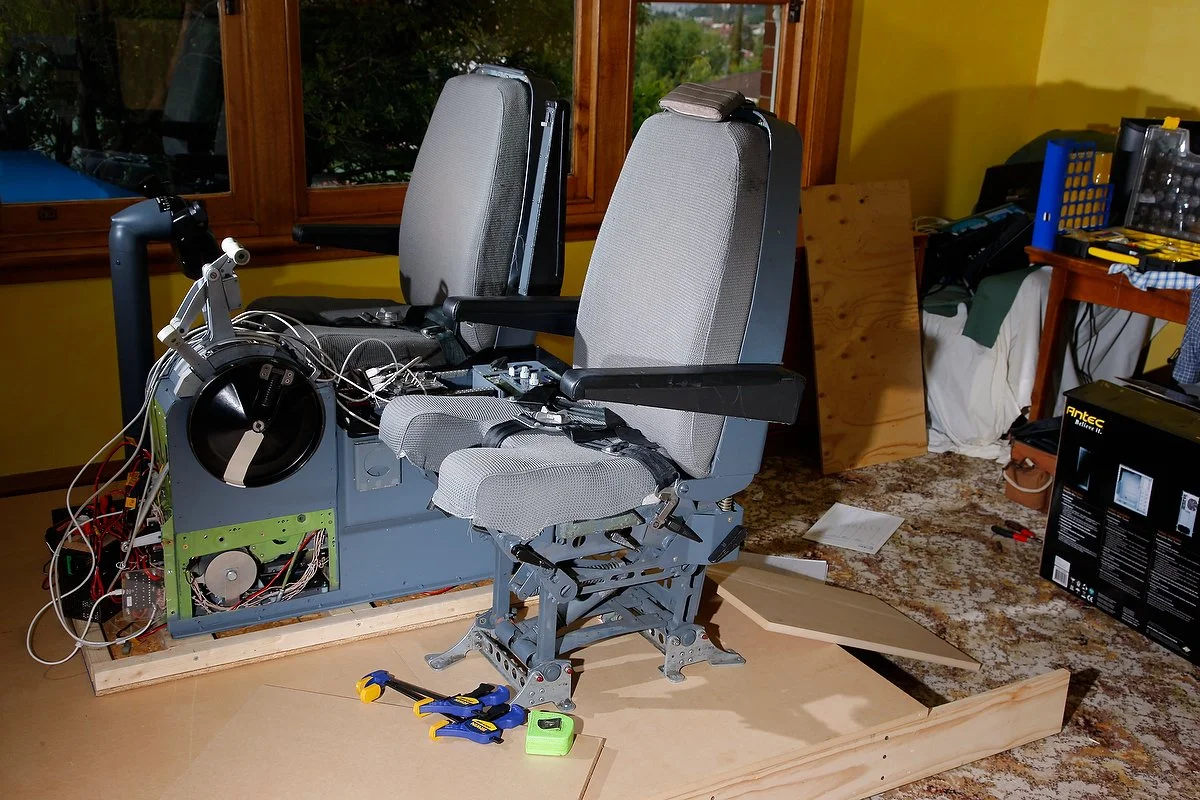
I know I will miss the narrower two-bay center pedestal.  A major advantage that will be lost is the ease in climbing into and out of the flight deck; the two-bay provided more room between the pedestal and the seats.  At some stage, I probably will need to install J-Rails because the seats I'm using are fixed-claw feet Weber pilot seats; J-Rails will be needed to allow lateral seat movement.

BELOW:  Montage of several images showing main visual differences between 737-300 classic series throttle quadrants and the 737 Next Generation. The 737-300 throttle is my old throttle but, the Next Generation throttle quadrant belongs to a mate of mine.

Montage of several images showing main visual differences between 737-300 classic series throttles and the 737 NG style throttle units. The 300 series TQ is my old throttle unit but, the NG Throttle quadrant belongs to a mate of mine

B737 Auto Brakes - Converting & Using a Genuine Auto Brake

oem 737-500 auto brake rotary and squib

Enthusiasts don’t normally give a second thought to the rotary type auto brake mechanism on the Main Instrument Panel (MIP); it works and that’s all that matters.  However, several reproduction rotarys do not entirely replicate the correct operation of the auto brake in the Boeing 737 aircraft.

In the real aircraft, a pilot has the ability to select between auto brake OFF, 1, 2, 3, and MAX.  The first three brake indications and off are achieved by turning the knob in a clockwise or anticlockwise direction, however, the knob stops at MAX.  To engage MAX, the pilot must pull the knob out from a retainer and then move it a further click to the right. 

The reason for this is quite simple; engaging auto brake MAX results in severe deceleration which can be stressful and uncomfortable for passengers, as well as creating undue wear and tear on the braking mechanism of the aircraft.  The function of pulling the knob is not replicated in reproduction auto brake switches.

Aviation Scrap Yard to Me

To my knowledge, the auto brakes operate and use the identical rotary mechanism throughout the Boeing aircraft series, the exception being the size and style of the actual knob mounted on the rotary.  The early model auto brake assemblies have a slightly larger knob, while those used in the 737-500 have a smaller knob that is identical to that used in the Next Generation aircraft (with the exception of the parallel black strips which is distinctly Next Generation) 

rear of own autobrake squib

Larger and Robust

If you have inspected any genuine aviation part, you will have noted that the size of the item is usually quite large in contrast to reproduction simulator part.  This is because a real part must be manufactured to take into account the nuances of pressure, fatigue, vibration, water and dust proofing, and be made as sturdy as possible to ensure operational longevity.  Genuine parts regularly are designed to military specifications and can withstand considerable abuse.   

Canon Plugs

The wiring used with an OEM part can appear complex with several wiring harnesses and a multitude of connections.  In a real aircraft, these wires connect to circuit breakers and a magnitude of interconnecting electrical components and power sources. All Boeing 737 aircraft use Canon plugs. Canon plugs make removing a panel straightforward for a technician and also provide a fail safe mechanism to ensure that specific wires are connected to their correct mate. Each Canon plug is different and can contain up to 32 differently arranged pin-outs. It is almost impossible to miss-mate two Canon plugs.  

With so many variables, it can be frustrating slow process determining which is the correct pin-out to use. 

Autobrake Mechanism -  Simpler than Most Conversions

The auto brake assembly is a lot simpler to convert than a more sophisticated avionics panel. 

If you already have an auto brake rotary and installed to your MIP, all you are doing is replacing the reproduction plastic rotary with a real OEM rotary.  The wires then connect to your interface card.  The only tricky part is determining which connection outlet on the real rotary to connect the wires to.  Determining this is either by trial and error or finding a schematic diagram for the rotary.  I was fortunate that I had access to the later…

using a dremel bit to carefully enlarge the hole in the panel so that the rotary shaft will fit correctly

Conversion and Retrofit

Remove from the MIP the reproduction auto brake rotary and front light plate.  Check to determine if the shaft of the genuine rotary will fit through the panel and MIP wall; the circumference of the hole may need to be widened.   If this is necessary, it’s important that you do not damage any IBL back lighting that maybe used in the light plate.  IBL is usually sandwiched between the back and front of the panel.

I used a dremel tool to gently and very carefully remove part of the light plate to allow the rotary to fit through the hole in the plate.  Do NOT use a drill as this may fracture the light plate.  

Fitting the Rotary Nut - Enlarging the Plate Recess

The rotary is securely connected to the MIP via a hexagonal-shaped nut.  Depending on your MIP manufacture, you may need to enlarge the hole on the rear of the plate to enable this hex nut to be recessed in the plate.  If you are using a MIP made by Flight Deck Solutions you will not need to do this as FDS have designed their MIP to fit genuine parts.  Use the dremel to gently enlarge the recess on the rear of the plate.  Be VERY careful not to damage the light plate; use the dremel tool very lightly.  

owm 737-500 auto brake squib showing multiple connectors and pin out codes

Wiring

The genuine rotary appears to look like a squid (the sea animal) with an assortment of wires emanating from screw connectors.

Remove all the wires and screws and thoroughly clean the unit with a suitable cleaner.  Do not discard the wires and connectors as you can probably reuse the high grade aviation wire; remember recycling is good and helps the environment.  You will note that each connector is marked by a printed number.  

The numbered keys for the autobrake squib keys and function are outlined below:

  • 31 - common or earth

  • 32 - RTO

  • 33 - OFF

  • 34 - autobrake 1             1

  • 35 - autobrake 2

  • 36 - autobrake 3

  • 37 - autobrake MAX

Replace the screws in the appropriate connectors you will need to use.  Then add a section of wire (use the old wire first) to the connectors.  If you cannot reuse the sturdy clips, then use automobile electrical tabs.

If you have not done so already, before you cut the wires from the (to be replaced) “plastic” rotary, mark with tape and pen which wires connect to what function – RTO, OFF, 1, 2, 3 & MAX.  This will make it an easier task when reconnecting or soldering the wires.

Aligning Rotary on MIP

Aligning the autobrake rotary is important if you want the selector knob to align correctly with the engravings on the MIP.  If you look carefully at a reproduction rotary you will notice a circular lug that often is mated with a hole in the receiving metal - this stops the rotary from spinning on its own axis.  OEM parts do not have such a lug.  Rather, they have a circular washer that has a lug attached to it.  This washer slides over the shaft of the rotary along a defined groove.  The lug on the washer then meets with an appropriately positioned hole in the MIP to stop the rotary from swivelling.

Interface Card

If you are replacing a reproduction unit with an OEM unit, then an interface card is not necessary - connect the wires from the new rotary to those cut from the removed from the plastic reproduction rotary either by solder or using a terminal block.

However, if this is a new installation a Phidget 0/16/16 interface card will be required to assign the appropriate locations of the knob to their respective functions.

Is There a Difference?

Can I notice and feel the difference between the older reproduction rotary and the genuine rotary?  In a nutshell - a resounding yes. 

The genuine rotary is firmer to turn, engages with a distinctive audible click, and feels more robust.  The knob also feels different to the reproduction knob; probably because the reproduction knob is made totally from acrylic and a genuine knob, although made from similar material, has a stainless shroud around the inside of the knob.  This causes the knob to feel more secure on the rotary.

Annunciators

The autobrake has two annunciators - the Anti Skid INOP and the Autobrake Disarm korrys.   The simulator uses OEM annunciators and although these korrys have been wired separately, their connection with the autobrake is done through the avionics software in use.

Below is a short video showing the use of the auto brake assembly.  Ignore the speed reference knobs and fuel reset switch that need to be replaced with OEM knobs.


Auto Brake Usage

The auto brake is designed as a deceleration aid to slow an aircraft on landing or in rejected take off.  The rotary switch has four settings: RTO (rejected take off), 1, 2, 3 and MAX (maximum).  The brake can be disengaged by turning it to OFF, by activating the toe brakes, or by advancing the throttles; which deactivation method used depends upon the circumstances and pilot discretion.  

RTO and MAX provide similar braking power (3000 PSI).  1, 2, 3 and MAX provide an indication to the severity of braking that will be applied when the aircraft lands.   Often, but not always the airline will have a policy to what level of braking can or cannot be used; this is to either minimize aircraft wear and tear or to facilitate passenger comfort.  

In general, setting 1 and 2 are the norm with 3 being used for wet runways or very short runways.  MAX is very rarely used and when activated the braking potential is similar to that of a rejected take off; passenger comfort is jeopardized and it’s common for passenger items sitting on the cabin floor to move forward during a MAX braking operation.  This 'safety feature' is the reason why Boeing airframes have been designed so that the pilot must pull the auto brake knob before selecting MAX.

If a runway is very long and environmental conditions good, then a pilot may decide to not use auto brakes favoring manual braking.

The pressure in PSI applied to the auto brake and the applicable deceleration is a follows:

  • Auto brake setting 1 - 1250 PSI / 4 ft per second.

  • Auto brake setting 2 - 1500 PSI / 5 ft per second.

  • Auto brake setting 3 - 2000 PSI / 7.2 ft per second.

  • Auto brake setting MAX and RTO - 3000 PSI / 14 ft per second (above 80 knots) and 12 ft per second (below 80 knots).

To activate the auto brake it must be armed by selecting the appropriate setting using the auto brake selector knob (1, 2, 3 or MAX).  Furthermore, for the auto brake to engage the throttle thrust levers MUST BE in the idle position at touchdown.  If the auto brake has not been selected before landing, it can still be engaged providing the aircraft is travelling no slower than 60 knots.

The auto brakes can be disengaged by either pilot by applying manual braking or selection the auto brake selector knob to OFF.  Either action will cause the auto brake disarm annunciator to illuminate for 2 seconds before extinguishing.

Important Facet

It’s important to grasp that the 737 NG does not use the maximum braking power for a particular setting (maximum pressure), but rather the maximum programmed deceleration rate (predetermined deceleration rate).  You can only obtain maximum braking pressure using either RTO or when depressing the brake pedals.  Therefore, each setting (other than RTO) will produce a predetermined deceleration rate, independent of aircraft weight, runway length, type, slope and environmental conditions.

Auto Brake Disarm Annunciator

The auto brake disarm annunciator is coloured amber and illuminates when the following conditions are met:

  • Self test when RTO is selected on the ground.

  • A malfunction of the system (annunciator stays illuminated - takeoff prohibited)

  • Disarming the system by manual braking during an RTO or landing

  • Disarming the system by moving the speed brake lever from the UP position to the DOWN detente position.

  • If a landing is made with the selector knob set to RTO (not cycled through off).  If this occurs the auto brakes are not armed and will not engage.  The annunciator will remain illuminated

The annunciator will extinguish in the following conditions;

  • Auto brake logic is satisfied and auto brakes are in armed mode.

  • If the thrust levers are advanced during an RTO or landing ( 3 seciond delay is allowed after the aircraft has landed).

Personal Preference and Anti-skid

My preference for using auto brakes is, that when conditions are not ideal (shorter and wet runways, crosswinds) - I devote my attention to the use of rudder (for directional control) without concern for braking... the machine does the braking, and I take care of keeping the aircraft on the center-line...

Anti-skid automatically activates during all auto braking operations and is designed to give maximum efficiency to the brakes, preventing brakes from stopping the rotation of the wheel, thereby insuring maximum braking efficiency.

To read more on this subject navigate to: Rejected Takeoff (RTO) - Review and Procedures.

BELOW:  Photo montage of auto brake assembly.  Final conversion lower right picture - ready to install to MIP.

Photo montage of oem 737-500 auto brake.  Final conversion lower right picture - ready to install to MIP

B737 Blanking Plates - Cover That Unsightly Gap

OEM blanking plates complete with DZUS fasteners recently removed from a scrapped 737 - the dirt and dust is still on them!  Note three differing sizes - 1" 2" and 4"

No matter what style of simulator you are using or have constructed, you will most likely have a center pedestal installed.  The pedestal will be either a two-bay or three-bay type and be a genuine aviation part incorporating DZUS fastener rails, or a reproduction unit manufactured from wood, metal or plastic.

The two-bay pedestals, once allotted the standard Boeing avionics suite, usually have no  space remaining for additional avionics; however, the three-bay pedestals have substantially more 'real estate' and often gaps are remaining that are not filled with avionics.  Most enthusiasts either leave this space open which looks very unsightly, or manufacture their own plate to cover the gap.

OEM Blanking Plates

Why not use the real part….  

Boeing produces several blanking plates in varying sizes to be used to cover any 'gaps' not used in the center pedestal, forward and aft overhead panel, or Main Instrument Panel (MIP).  These plates are machine-grade light weight steel (or aluminum), are painted Boeing grey, and incorporate the required number of DZUS fasteners for attachment to DZUS rails.  The plates come in a variety of sizes with 1 inch, 2 inch, and 4 inch being the norm.

These plates are inexpensive and usually retail between $5.00 - $20.00 USD, and not only fulfill the task of covering an unsightly gap, but are easy to install, come pre-cut, are painted the right colour, and usually have DZUS fasteners attached to them. 

If not using real DZUS rails and your pedestal in made from wood or plastic, then it’s relatively easy to remove the fasteners and replace them with reproduction screw-type DZUS available from GLB Products.

Most aircraft wrecking yards carry these plates, as airlines regularly purchase them.  Failing this E-Bay often has blanking plates for sale. 

OEM Boeing 737 Control Columns - A Closer Look

OEM Captain-side 737-500 series control column.  Previously used by Croatian Airlines

The two control columns have been refurbished and installed into the simulator.  The control columns previously were used in a 737-500 airframe operated by Croatian Airlines. 

I was fortunate to have been able to secure these columns, and although there is some wear on the yokes, the buttons, electric trim switches, chart holders, and trip indicators are operational and in good condition.  Furthermore, a working stick shaker is attached to the captain-side control column.

In this article, I use the words control columns and yoke interchangeably.

Mechanical Set Up

To allow the two columns to be fitted to the 5 inch high platform, the lower cogs have been removed and replaced with bearings.  The bearings support a high strength stainless shaft that connects to a rotating disc beneath each of the columns; movement is synchronised between control columns.

Physical movement of the control column is registered by high-end string potentiometers and any movement converted to an electrical signal that can be read by the interface card.  The interface card used is a Leo Bodnar 836X joystick controller.

The interface card, electrical wiring and potentiometers are installed on a piece of plastic board mounted to a dust proof box and attached to the underside of the platform.  Access to the box is via the front of the platform.

Push and Pull Pressures

In the real Boeing 737 aircraft the control columns are hydraulically driven, and a fail-safe cable mechanism provides redundancy should the hydraulics fail.  The 737 is rather unique in that, although hydraulics control movement of the control column, the pressures needed to move the columns (by hand) are quite stiff.  Therefore, hand flying a 737 can be quite tiring; you must use a little muscle to move and maintain the position of the controls.

The specifications for the real aircraft state that the control column has a 37 pounds push/pull value +- 4 pounds, while the roll pressures are 12 pounds +- 3 pounds.  These pressures can differ from aircraft to aircraft, but fall within the published specifications. To replicate the push, pull and roll forces as accurately as possible, four heavy duty springs have been fitted to the column mechanism. 

Heavy duty pre-tensioned springs provide accurate static control loading

The control column pressure can be adjusted by either replacing the springs with higher or lesser tension springs, or by disengaging the outer springs. 

A pressure test determined that push/pull pressure is 20 pounds and roll pressure 15 pounds.  The push/pull pressure is on the low side, however, will be left as is for the time being.  Springs have been used rather than hydraulic rams due to the simplicity of a spring and ease of replacement.

Although the use of springs is rudimentary, it's acts as an interim measure until control force feedback is installed.  When this is done, the force required to move the control column will alter based on aircraft's speed, flap setting, landing gear position and other environmental variables.

The video at the bottom of this article demonstrates the linkage mechanism and springs in motion.

Configuration - Movement and Buttons

Configuration of the control columns is straightforward. Although there are two control columns, each column is linked to the other.  Therefore, only one interface card is required.  The buttons on the yoke, and the electric trim switch are connected to the outputs on the interface card.

Initial registration of the movement of the yoke and buttons is established in the Windows joystick calibration software.  Further calibration is either done directly in the flight simulation program, FSUIPC, or in ProSim737.  Although it is possible to assign buttons directly via the flight simulator set-up menu, the preferred method is to use FSUIPC or ProSim737.

Backlighting (Trip Indicators)

The actual yoke doesn't have backlighting; any illumination of the yoke is achieved by focusing the map light which is attached to the overhead panel.  However, the numbers on the trip indicators do have backlighting (to illuminate the numbers). 

Trip indicators are an airline specific option and do not come as standard issue.  Pilots use the trip indicator to 'scribe' the flight number of the flight, or to document the Vref speed.  Some crews never use the indicators.  I use the trip indicator as a ready memory pad to document the landing Vref speed (Vref+5).  The backlighting for trip the indicators is powered by 5 Volts.

oem chart holder and cheat sheet

Chart Holders

The chart holder is used to secure the approach plate (paper chart) in an area that it can easily be read during flight operations.  The chart holders have a folding mechanism beneath the plate that allows the holder to be either pushed flush to the yoke, or positioned at a user-selected angle. 

Another function of the chart holder is to provide a ready memory jogger for specific flight modes (checklist).  The adhesive transfer on which this information is printed is specific to each aircraft type and /or airline.  illumination of the chart plate, like the yoke, is achieved using the map light.

OEM Verses Reproduction

Several companies manufacture reproduction control columns: Precision Flight Controls (PFC), CH Products, Revolution-Sim and Ace Engineering to name a few.  Over the years I have used products from ACE, CH Products and PFC.  Without transgressing into a 'tit for tat' argument, you get what you pay for.  

A CH yoke retailing at $100.00 cannot be compared with an ACE yoke retailing around $1300.00, however, both products have been manufactured to cater towards differing segments of the market.  This said, the difference between ACE and PFC is marginal.  I cannot comment on Revolution-Sim having not used their products. 

So what is the different between a high-end reproduction yoke and a OEM yoke and column?

The main difference is the feel and finesse of the genuine item.  Boeing has spent a lot of money (more than PFC, ACE or Revolution-Sim combined) in the development and engineering of the control column, and this is very difficult to replicate in a reproduction.

The OEM yoke and column is engineered to provide faithful service for many years.  It's also built to suffer use and abuse from real-world pilots, and I am certain anything a virtual pilot can throw at it, will not cause any damage.  The buttons and electric trim switches are solid, feel good to manipulate and are very reliable.

Yoke Performance

The yoke moves left and right across its range of motion with a smooth and silky feel without staggering, binding or rough patches.  Likewise, the columns move forward and aft very smoothly.

The electric trim switches are far more responsive than the reproduction switches I have used.  A slight application of pressure to the switch engages the electric trim.  The electric trim switches response is a akin to a hair trigger on a firearm - it only needs a light touch to engage. 

The control column is very responsive, and if calibration has been done correctly, very accurate.  If the yoke is turned 15 degrees to the left, the measurement on the aileron tape is exactly 15 degrees.

Synchronization

I was concerned that synchronisation between the two control columns would not be perfect, however, my concern was short-lived.  The use of high-end bearings at the end of the control linkages removes any chance of slop (loose movement) between the two control columns. 

Yoke Switches

  • OEM 737 yokes have several switches and buttons.

  • Momentary press push button - auto pilot deselect.

  • Momentary rocker switch - electric trim up/down. This switch is interesting as it incorporates redundancy.

  • Momentary rocker - push to open channel (push to talk PTT).

  • Rocker switch - Intercom.

  • Trip Indicator - used as memory aid for flight number.

oem 737 flight controls in simulator

Appearance of Yoke - Used Look

If you carefully study the pictures of the yokes, you will observe that the yokes are not pristine condition, but show solid use (and probably abuse when it was striped from the aircraft).

The baked-plastic covering of the yoke shows scratches and some of the metal has been rubbed clean of paint.  Some enthusiasts dislike this look and prefer a brand new 'out of the showroom' appearance.  If this is you, then I suggest an OEM yoke may not be for you, unless you wish to completely overhaul the yoke and pay the large amount of money required to re-bake the plastic coating.

I like the 'used' look and feel it adds to the simulator.  I have been in many cockpits, and very rarely do you find a flightdeck in brand new condition, other than in the first few months of service.  More often than not, gauges, yokes and panels are scratched, dented and stained from many hours of sustained use from individuals that are more interested in flying, and going home after the flight, than maintaining the desk!

Below is a short video showing the under floor mechanism, springs and linkage rods.  If you listen carefully you will hear the springs creaking.  This is not an issue when the simulator is running as any noise is cancelled out by the noise of the engines and flight deck ambient noise (electrics, 400 hertz noise and wind).


Glossary

Control Wheel - Yoke.

FSUIPC - Flight Simulator Universal Inter-Process Communication (interface software that provides a bridge between flight simulator and outside programs).

OEM - Original Equipment Manufacturer (aka real aircraft part).

  • Updated 20 June 2020.

Using Genuine B737 Aviation Parts

A colleague grinding the tails from genuine DZUS fasteners. These will then be attached to reproduction modules to enhance their appearance

There is something fundamentally different when using a genuine piece of aircraft equipment instead of a replicated item – It’s difficult to define, but the idea of using a piece of hardware that flew thousands of flight hours, in good and bad weather, has a certain appeal.

You will notice when you peruse the below list that many parts are not Next Generation, but are from classic 737 airframes, Finding Next Generation components is time consuming and can have long lead times. In the interim, I am using classic parts as fillers. Fortunately, some components used in the classics, especially the 737-500 are also used in the Next Generation.

The following OEM parts are currently used and converted:

  • 737-500 yokes and columns (2)

  • 737 Captain-side stick shaker

  • 737-300 throttle quadrant

  • 737-300 telephone and microphone

  • Jetliner style aviation headset (was formally used in an United B737)

  • 737-300 three-bay center pedestal

  • 737-400 fire suppression panel

  • 737 yoke trip indicators (2)

  • 737 rudder pedals (2)

  • 737-500 audio control panels (2)

  • 737 Weber captain and first officer seats

  • MD-80 clock (flight officer side of MIP)

  • 737 overhead map light

  • 737 korry switches

  • 737-500 tiller handle

  • 737-300 Forward & Aft Overhead Panel w/ Coles engine switches & genuine light switches

  • DZUS fasteners

  • 737-800 flap guage

  • 737-800 Yaw Dampener gauge

  • 737-800 brake pressure gauge

I would like very much like to replace the ADF and NAV modules with OEM panels; however, need to research the feasibility in doing this.  In the meantime, I’m using reproduction navigation radios manufactured by Flight Deck Solutions.

Historical Significance

The historical significance of using genuine parts cannot be ignored.    It’s relatively easy to research an aircraft frame number or registration number and in the process learn where the aircraft was used and in what conditions.  

For example, the throttle unit I am using was removed from a South West B737-300 that plied the continental USA for many years, whilst the yokes and columns were previously used in a B737-500 operated by Croatian Airlines.  The clock I have for the flight officer side of the MIP came from a FedEx MD80 and one of the ACP units was used by Aloha Airlines in Hawaii.

Recycling

Using OEM used parts helps the environment!  

For a start, you are not purchasing new reproduction parts made from virgin resources.  Secondly, the used parts you bought probably would have been destined for expensive recycling, or alternatively disposed of to landfill.  

Recycling can be fun!!  

It’s a good feeling to convert something destined for disposal and bring it back to life.

Toughness

One of the major benefits of using OEM aircraft parts is their longevity and ruggedness.  Whilst none of us want to damage our simulators through over zealous use; it can and does occur from time to time.  Replica parts are – well a little delicate.  To ensure long life you must treat them with care.  

It’s the opposite with genuine aircraft parts; damaging a genuine part with normal use is almost impossible.  

For example, a speed brake lever is relatively easy to bend or break on any number of replica throttle quadrants on the market; damaging a genuine speed brake handle is very difficult as they are constructed from high grade materials to withstand genuine stresses (pilot-driven or otherwise).

Simulation pilots are often as rough on their gear as genuine pilots are; I’ve seen simmers jab ACP buttons with enough force to break a piece of plastic.  Genuine buttons are made to withstand this heavy-handed treatment, replica parts – break!

Aesthetics – Look Your Best

It’s a fact; aN oem aircraft part looks 100% more realistic than a simulated part – that’s obvious.  If your center pedestal has an assortment of genuine modules mixed in with replica modules, the pedestal will appear much more authentic than one comprised solely of simulated units.

You will be surprised that small things can make a huge aesthetic difference.  Take for example, DZUS fasteners.  I bought a box of fasteners sometime back and use them wherever I can to replace the reproduction fasteners or screws that many manufacturer’s use.  If the fastener does not fit the appropriate hole in the reproduction module, I either enlarge the hole with a drill bit, or if this isn’t feasible, I cut the tail from the fastener leaving only the DZUS head.  I then use a piece of sticky blue tack or crazy glue to secure the DZUS head to the appropriate part.  

OEM B737-300 two-bay center pedestal showing mix of reproduction and oem components

The fasteners I've used were purchased second-hand; therefore, they show wear and tear.  I don’t mind this used and abused look.  Yes it sounds rough and ready, but the end result looks very pleasing to the eye and more faithful to what you would see in an operational flight deck.

The confines of the flight deck are not as clean as one might expect, and instruments are scratched and dented; pilots rarely concern themselves with aesthetics and technicians complete their maintenance quickly, as an aircraft not flying equates to lost revenue for the airline.

The use of genuine parts adds to the immersion factor, and as a Dutch simmer recently commented: “It makes the simulator more alive”

Availability of Parts

oem aircraft parts can be difficult to find and it’s a hit and miss affair.  As newer aircraft are brought online, airlines scrap their older fleet and parts become readily available.   

Finding late model Next Generation parts, at a reasonable price is almost impossible; these parts are still serviceable.  Parts in older aircraft may also be serviceable; however, they must meet safety regulations and be inspected and approved by a certified agency.  This process is expensive and many airlines find it cost prohibitive; therefore, parts are sold as scrap.

E-Bay can be a good place to find parts.  Search for aviation parts - Boeing, 737 or Gables.  Aviation scrap yards are also invaluable, as are the classified sections in various flight simulation forums on the Internet such as My Cockpit and Cockpit Builders.

Conversion - Use in Flight Simulator

This can be minefield to the uninitiated.

OEM parts often operate on a variety of voltages, and it’s not uncommon to need 5, 12, 18 and 24 Volt power supplies to enable an OEM part to work correctly.  Further, the wiring inside the neat-looking box can be a rat’s nest of thin wires weaving their way to and from a variety of unidentified pieces, before terminating in an electrical connection rarely found outside the aviation industry (Canon plug).

I am not an expert in conversions (although I am learning quickly.....).  I’m lucky in that I have access to a few people who are very knowledgeable in this area and are happy to share their knowledge with me.  

Interfacing

There are a number of ways to interface an OEM part with flight simulator.  The easiest is to use is a Leo Bodnar BU0836 joystick card, or similar, using standard flight simulator commands and/or FSUIPC.  The use of these cards makes assigning functionality in flight simulator very easy and straightforward.

One BU0836 card provides 12 inputs which correlates to 12 individual switches or buttons.  The 0836 card also has the capability to have a matrix constructed which increases the number of available outputs.  Another joystick card that is very good and easy to configure is the PoKeys card.

The inside of a 737-500 ACP module showing the rat’s nest of wiring that can be found within an OEM module

For functionality that requires movement, a servo motor will need to be used and configured in FS2Phidgets.  Phidgets allow you to program almost any moving part, such as the needle of the rudder trim module or the trim wheels of a throttle unit.    Digital servos are better than analogue servos as the former do not make an audible squeaking noise when connected to power.

By far, the most difficult part of any conversion is discovering what wire connects to what functionality.  Finding the wire can be challenging in itself as most avionics modules are a nest of wires, diodes and electronic circuitry.

You Have A Choice

You don’t have to use reproduction simulator parts throughout your flight deck – there is a wide selection of used aviation parts available, and with a little searching, you probably can find what you want.  

OEM parts frequently can be found at far less cost than their reproduction counterparts, and in every case will always look more visually appealing.  If you’re not up to the task of conversion, there are individuals that can convert modules for you.  You will then need to configure the functionality in FSUIPC or directly in the avionics suite used.  At the very minimum, using DZUS fasteners will bring your simulator to the next level of realism.  But be warned, using OEM parts evokes a desire to replace anything replica with something real.

In my next post we will look at converting two genuine B737 Audio Control Panels (ACPs) to flight simulator use.

Installing Weber Pilot Seats to Platform Base

oem 737-500 weber claw feet and platform mount

The Main Instrument Panel (MIP) is an integral part of the flight deck.  Now that it is installed, other components can be measured and fitted to the floor platform.  I wanted to install the eats correctly, even though the platform is a interim platform and will be replaced with an aluminum box platform sometime in the future,

The two Weber seats would take considerable time to attach to the platform, as unlike Ipeco seats they do not use a J-Rail system, but use claw feet. The feet must be positioned correctly onto the platform floor.

Attachment Stress

oem weber seat mechansim

In my earlier posts, I mentioned that to manipulate the various levers which move the seats results in relatively large amount of stress being placed on the attachment points of the seat to the platform floor; there is reason Weber seats have 16 attachment points to the flightdeck floor. 

To minimise the chance of the seat moving when adjusted, I fabricated a mount that sits beneath each seat.  The mount, constructed from wood, is 16 mm in thickness and is bolted to the 16 mm thick platform floor (36 mm total thickness).  Rather than use wood screws to attach the seats, I decided to use 55 mm length bolts with washers; my thinking is that the bolts will provide far stronger attachment points, when installed through the seat mounts and platform floor, than wood screws. 

Attaching the Seats

The first task was to cut and paint the seat mounts which was straightforward. Each seat was then attached to its mounting base and then secured to the platform in the correct position with bolts. The biggest problem was actually lifting and moving each seat into position on the platform, each seat and segment of flooring weighs over 50 kg.

Correct Positioning

The correct positioning of the seat and seat mount is very important.  Boeing specification states that the distance from the front of the seat to the MIP is 340 mm, however, this depends on where you are measuring to and what type of MIP you are using.  The measurement if using a FDS MIP is from the front of the claw feet to the forward edge of the lower kickstand.  This measurement is 440 cm.

wooden platform mount connected to claw feet of weber seat. the seat and mount are them positioned correctly on the platform and secured using bolts

The seats move forward and aft, by pivoting over the secured claw feet (see video); therefore, if the measurement is out by a cm or so it is not really an issue as the seat movement can take up the difference. 

It Works….

With the platform floor secured to the base it was time to trial the seats.  Both seats work well and there is no movement or flexing at their attachment points.  There is also no movement where the seat mounts join the platform floor.

I think it was overboard using 16 bolts and bolting through 36 mm of woo!  But, I wanted to make sure the seats did not move on their base as I didn't particularly want to remove them and start over again. 

Next on the list is installing the ACE yoke and throttle quadrant.

The wooden platform has since been replaced with a modular aluminum structure.

Weber Captain & First Officer Pilot Seats

weber seats on trailer

A call from DHL Freight logistics alerted me to the fact that another large crate had arrived at the local airport for pick-up.  It was too early for the consignment to be the MIP, so the next contender was cockpit seats.

I wasn’t going to purchase pilot seats until the project was nearing its final phase.  However, genuine B737 seats are becoming more difficult to find in good condition, and when I was offered these seats, I decided to purchase them. 

Boeing aircraft use for the most part two types of aircraft seats: Ipeco and Weber; the former being the more modern seat design with adjustable J-rails.  Personally, I find the Ipeco seats to be rather uncomfortable and the configuring of J-rails can be painful.  Weber seats bolt directly to the floor, so as long as you have the correct measurements for the bolt down locations, there shouldn’t be any further problems.  Both the Ipeco and Weber seats have several seat levers to allow for correct and comfortable positioning.

Weber seat cushions are either manufactured from cloth, which are the seats I have, or they have sheepskin covers sewn over and into the cloth.  At some stage in the future, I may have sheepskins installed over the seats, but at the moment this is a secondary issue.

Apart from some very minor cosmetic issues associated with the plastic molding on the rear of one seat, both seats are in excellent condition.  You have to remember that seats are always in used condition and probably have flown thousands of hours.  Before their new home in the simulator, they were fitted to a 737-500 series aircraft belonging to South West Airlines. 

Minor Overhaul of Flight Officer Seat

Although cosmetically the seats look OK, the right hand seat (flight officer) didn't seem to be operating correctly.  Inverting the seat, I was shocked to see a built up of dirt, grim and dust over the mechanism that controls the movement of seat.  Disassembling the components, I also discovered a broken split pin which was stopping the connecting cable, which controls the vertical rise in the seat, from working.  After cleaning and replacing the broken split pin, I lubricated all the areas requiring lubrication.  PRESTO, the seat now works as it should.

Leg Attachment Points - Four Seat Movements

Each seat has 16 attachment points to secure the seat to the floor.  One reason for this is that when you alter the position of a Weber seat, especially forward and aft, the pressures exerted on the seat legs are very high.  The seat has four movements: back reclining (like in a motor car), vertical rise (upwards lift of about a foot or so in height), under leg lifting and forward and aft seat control.  The last movement is needed as Weber seats do not use rails.

CASA Approved?

I was inspecting the seat feet (called duck feet because of their shape when my wife came into the room - she commented ’I hope their CASA approved’.  The first snipe - no doubt more will come  :)  I dare not try the seat harness.... (CASA is the Civil Aviation Safety Authority in Australia)

Oh and before you ask - yes the seats are very comfortable.

DZUS Fasteners

OEM DZUS FASTENERS AND RAIL

When I became interested in constructing a simulator, I heard knowledgeable people stating DZUS this or that - I had no idea what these individuals were referring to, let along how to pronounce the word.

Dzus (pronounced Zooss) is a proprietary name for a type of quarter-turn fastener often used to secure skin panels on aircraft.

It was invented and patented by a native Ukrainian William Dzus (Volodymyr Dzhus) in the early 1930s. Quarter-turn fasteners are used to secure panels in equipment, airplanes, motorcycles, and racing cars that must be removed often and/or quickly. These fasteners are notable in that they are of an over-center design, requiring positive sustained torque to unfasten. A DZUS fastener will correct itself rather than proceed to loosen as it would in threaded fasteners.

Real DZUS Fasteners

Finding individual real DZUS fasteners can be difficult as they are mostly attached to avionics panels, and the vendor wants to keep them with the panel. If you search long enough, eventually you will find an aviation scrap yard that has them available as separate units. I recently saw several selling on e-bay quite cheaply. I have a small collection of grey, black and bare metal coloured fasteners in varying condition, obtained from a scrapped Boeing 737 (I bought them in a 30 piece lot). The fasteners are needed to lock down any avionics panels to the DZUS rails of the OEM center pedestal and overheads and some panels in the MIP.

Reproduction DZUS Fasteners

If you’re using a OEM center pedestal with a DZUS rail, reproduction panels such as those produced by CP Flight or SISMO will not be able to secure to the rail easily. You will need to enlarge the circular hole along the edge of the module to allow the real DZUS fasteners to fit easily and correctly. If you decide to do this, be mindful that you don’t damage the edge of the module when you enlarge the circular hole. I used a titanium drill bit and carefully secured the panel in question in a vice on a workshop bench (wrapped carefully to avoid the vice jaws damaging the module) before drilling.

If you have replicated the center pedestal from MDF or wood and want to use something more realistic than boring screws to attach your panels, you can purchase after market'look alik’ DZUS screws. Basically these are wood screws with DZUS style heads on them. Good quality aluminium DZUS screws can be purchased from GLB Flight Products. I’ve used these on my earlier generic flight deck and they work very well and look just like the real ones…

Acronyms

OEM - Original Equipment Manufacturer.

Sticky Autothrottle Button - Repaired

oem autothrottle button. note the circular circlip

I noticed soon after the throttle quadrant arrived that the engine number one auto throttle button was a bit sticky.  Depressing the button, it would stay pressed in for a few seconds even though pressure had been released.  The autothrottle buttons are one-way buttons meaning that they are click buttons.  It’s probable that after many hours of service, sweat, dead skin cells and dirt has built up on the inner button behind the spring mechanism; a friend suggested that DNA analysis of the built up debris would probably provide a list of suspect pilots!

Whilst the button was still in place, I attempted to loosen the built up material using a can of pressurized electronic cleaner fluid.  The fluid, I hoped would dislodge any loose material before evaporating.  Unfortunately, this didn’t work in the long run, although once lubricated with the evaporate solvent, the button operated correctly for a short time.

oem autothrottle button removed

Circlip

The button is held in place within the throttle handle by a ½ inch circlip.  Beneath the circlip and button there is a spring mechanism that pushes the button out after being depressed.  Using a pair of circlip pliers, I very carefully removed the circlip making sure that the spring mechanism of the circlip didn’t propel my button out the window and into the garden! 

With the circlip removed, the inner portion of the throttle handle slides out revealing the button and attached wiring.  The button is a modular design (shaped to fit inside the throttle handle) and unfortunately cannot be disassembled further, Therefore, I reassembled the button and sprayed a small amount of silicone spray around the button, allowing the silicone solution to penetrate around the the edge of the button. 

The silicon lubricant (which is non conductive, so there is no issue with power shorting) seems to have solved the problem as the button no longer sticks, however, this is only an interim solution.  I'll search for a replacement button module.  Sometimes the most simple solution will fix your problem.

No doubt I can purchase a new replacement from Boeing for err $800.00....  I think not.  Eventually I'll find a disused button module in my travels.