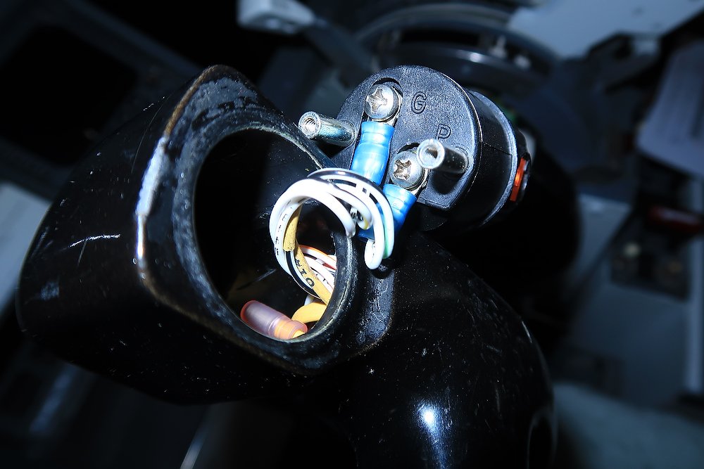
OEM Trip Reminder Indicator

Trip Reminder Indicator.  A small OEM part that is easily installed to any simulator

The trip reminder indicator (TRI) is a mechanical device installed to the right hand side of the yoke; it’s an airline option.  Basically, the device is three separate digits that can be rotated in any combination, from zero to nine.

The trip indicator is a memory device from which the crew historically used to record the flight number; the pilot uses his thumb to move the three digits to indicate the flight number.  However, over time flight numbers became longer than three digits and the use of the trip indicator, for it’s intended purpose, wanned

I use the trip indicator to dial in the Vref, as it’s often easier to quickly glance at the trip indicator to remind you of the Vref speed rather than look at the PFD or CDU.  Some dial in the Vref + wind speed.

Background

The trip indicator has a very long lineage beginning with the Boeing 707 aircraft.  The device was then ported to the 717, 727 and finally the 737 Classic and Next Generation airframes.

Installation and Backlighting

Because the OEM yoke already has the correctly shaped hole, installation of the trip indicator is straightforward.  If you are using an OEM yoke, you probably will need to carefully remove the blanking cover from the hole.

If a reproduction yoke is used, and the hole is not present, a circular hole will need to be cut from aluminium or plastic to enable the trip indicator to fit snugly into the yoke.  As the three dials are mechanical, there is no requirement to connect the device to an interface card.

Each of the digits on the indicator is backlit by a 5 volt incandescent aircraft bulb. 

The design of the trip indicator is ingenious, in that after the trip indicator has been removed from the yoke (two screws at the front of the yoke secure the indicator), a transparent acrylic slide can be unlocked to slide laterally from behind the three digits (see picture).  The acrylic slide accommodates three 5 volt bulbs, each in its own compartment.

To enable the backlighting to function requires two wires (positive & negative/common) to be connected to the appropriate connection on the rear of the trip indicator, and then to a 5 volt power supply.  The amperage draw from the three bulbs is minimal.  The wiring should be run through the yoke and down the control column so that it comes out at the bottom of the column.

In the aircraft, the backlighting for the trip indicator is connected to the panel light knob located on the center pedestal.  This enables the backlighting on the trip indicator to be turned on and off or dimmed. 

Final Call

The trip reminder indicator is but a small and unobtrusive item, however, it’s often the small things which add considerable immersion and enjoyment when using the simulator.  The trip indicator is also an OEM part that can be very easily installed to a reproduction yoke with minimal experience in fabrication and wiring.

Glossary

OEM - Original Equipment Manufacture.

Ground Effect - Historical Perspective & Technical Explanation

During the Second World War, a crippled Boeing B17 was struggling to maintain altitude.  The aircraft and eleven crew members were over occupied Europe, returning to England, following a successful bombing mission.

Searchlights, Flak & Enemy Fighters

After negotiating the enemy searchlights that probed the darkness over their target, and then being struck by shell fragments from anti-aircraft flak, they were pounced upon by German fighters on their homeward leg.  The ensuring fight was dramatic and left the damaged bomber with only two engines running and third engine having difficulty.  As the bomber approached France, the enemy fighters, starved of fuel, aborted their repetitive attacks, but the damage had been done.  Loosing airspeed and altitude the aircraft could not maintain contact with the Bomb Group; soon they were alone.

The captain, in an attempt to maintain altitude, requested that everything heavy be jettisoned from the aircraft.  This included machine guns, ammunition and damaged radio equipment; soon the B17 was a flying skeleton if its former self.

The Captain was concerned that a fire may develop in engine number three as it was spluttering due to a fuel problem.  The Captain did not need to concern himself much longer, for the engine began to cough uncontrollably before vibrating and ceasing to function.   The aircraft was now only flying on one engine – something not recommended, as it placed great strain on the engine and aircraft superstructure.  

The aircraft continued to loose altitude despite the jettisoning of unwanted equipment.  The Captain decided it was better to ditch into the English Channel rather than land in occupied France.  His thinking was that Air Sea Rescue maybe able to pick them up, if their repeated morse code (SOS) had been received by England.  The power of one engine was nowhere enough to maintain such a large and heavy aircraft and the crew prepared to ditch into the freezing cold water of the channel.

We’re Going In – Good Luck Boys!

“Get ready guys, we’re 300 feet above the water” yelled the Captain into his intercom system.  “As soon as we hit bust them bubbles and get out.  Try to get a raft afloat”.  “Link up in the water  – Good Luck!”

Everyone expected the worse.  Surviving a ditching was one thing, but surviving in the cold water of the English Channel in winter was another!  The rear gunner, since moving forward sat close to escape hatch and gingerly rubbed his rabbit’s foot; he had carried this on every mission.  The side gunner fumbled repeatedly with his “lucky” rubber band, the bombardier sat in private thoughts, a photograph of his loved one held tightly in his hand, and the navigator frantically punched his morse set trying to get the last message out before fate took command of the situation.

The aircraft, although trimmed correctly, slowly began to dip towards the sea.  But at 60 odd feet above the waves, the aircraft began to float  – it felt as if the aircraft was gliding on a thermal.  For some reason the aircraft didn't wish to descend.  The remaining engine screamed its protest at being run at full throttle, however the horizontal glide continued. 

The Captain was amazed and thankful for whatever was keeping this large aircraft from crashing into the sea.  It was as if the B17 was cruising on a magic carpet of air – why didn’t it crash.  

A tail-wind assisted in pushing the B17 toward England and safety; seeing the English coast in sight, the navigator quickly calculated a route to the nearest airfield closest to the coast.  Twenty minutes later the bomber lumbered over the runway.  The only way to land was to reduce power to the remaining engine and push the control wheel forward, thereby lowering the pitch angle.  They were home and safe!

Divine Interaction, Luck, or Skill ?

The crew thought it was divine interaction that the bomber had not crashed – or perhaps luck!

Aviation engineers were baffled to what had occurred.  The aircraft had glided many miles above the surface of the English Channel and had not crashed.  Boeing, in an attempt to unravel what had occurred, repeated the event in the confines of a wind tunnel, to realize that what had maintained the large aircraft airborne was not divine interaction, but the interaction of what has since been termed Ground Effect.

The above account, although embellished in detail, did occur.  The mishaps of this bomber during the Second World War demonstrated a previously unknown phenomenon - Ground Effect.

Ground Effect – Technical Explanation

Ground effect refers to the increased lift and decreased drag that an aircraft wing generates when an aircraft is about one wing-span's length or less over the ground (or surface).  The effect of ground effect is likened to floating above the ground - especially when landing.

When an aircraft is flying at an altitude that is approximately at, or below the same length of the aircraft's wingspan, there is, depending on airfoil and aircraft design, a noticeable ground effect. This is caused primarily by the ground interrupting the wingtip vortices, and the down wash behind the wing. 

diagram 1: ground effect in the air

When a wing is flown very close to the ground, wingtip vortices are unable to form effectively due to the obstruction of the ground. The result is lower induced drag, which increases the speed and lift of the aircraft.

The two diagrams depict aircraft in ground effect whilst on the ground and in the air.

diagram 2: ground effect on the ground

A wing generates lift, in part, due to the difference in air pressure gradients between the upper and lower wing surfaces. During normal flight, the upper wing surface experiences reduced static air pressure and the lower surface comparatively higher static air pressure. These air pressure differences also accelerate the mass of air downwards.  Flying close to a surface increases air pressure on the lower wing surface, known as the ram or cushion effect, and thereby improves the aircraft lift-to-drag ratio.  As the wing gets lower to the surface (the ground), the ground effect becomes more pronounced.

While in the ground effect, the wing will require a lower angle of attack to produce the same amount of lift. If the angle of attack and velocity remain constant, an increase in the lift coefficient will result, which accounts for the floating effect. Ground effect will also alter thrust versus velocity, in that reducing induced drag will require less thrust to maintain the same velocity.

The best way to describe ground effect and which many people, both pilots and passengers, have encountered is the floating effect during the landing flare.

Low winged aircraft are more affected by ground effect than high wing aircraft. Due to the change in up-wash, down-wash, and wingtip vortices there may be errors in the airspeed system while in ground effect due to changes in the local pressure at the static source.

Another important issue regarding ground effect is that the makeup of the surface directly affects the intensity; this is to say that a concrete or other hard surface will produce more interference than a grass or water surface.

Problems Associated With Ground Effect

Take Off

Ground effect should be taken into account when a take-off from a short runway is planned, the aircraft is loaded to maximum weight, or the ambient temperature is high (hot).

Although ground effect may allow the airplane to become airborne at a speed that is below the recommended take-off speed, climb performance will be less than optimal.  Ground effect may allow an overloaded aircraft to fly at shorter take off distances and at lower engine thrust than normal.  However, the aircraft will not have the ability to climb out of ground effect and eventually will cease to fly, or hit something after the runway length is exceeded.

Approach and Landing

As the airplane descends on approach and enters ground effect, the pilot experiences a floating sensation which is a result from the increased lift and decreased induced drag value. Less drag also means a lack of deceleration and could become a problem on short runways were roll-out distance is limited.

Therefore, it's important that power is throttled back as soon as the airplane is flared over the threshold and the weight of the airplane is transferred from the wings to the wheels as soon as possible.

How to Counter Ground Effect

To minimise ground effect on landing, the following must be addressed:

  • Pitch angle should be reduced to maintain a shallow decent (reduces ability of the wing to produce more lift).

  • Thrust should be decreased.

  • The power should be throttled back as you cross the threshold at ~RA 50 feet (note that in simulation ~10-15 feet is more effective).

  • Land the aircraft onto the runway with purpose and determination.  Do not try and grease the aircraft to the runway (often called a carpet landing).  The weight of the aircraft must be transferred to the wheels as soon as possible to aid in tyre adhesion to the runway (also important when landing in wet conditions).

Does Ground Effect Occur in Flight Simulator?

If the aircraft is not set-up correctly, ground effect will definitely be experienced in a flight simulator. 

If you have ever wondered why, after reducing speed on an otherwise perfect approach, your aircraft appears to be floating down the runway, then you have already experienced ground effect.

Video - Operational Trim Wheels & Indicators

Now that the throttle quadrant is operational, USB hubs working and the Phidgets correctly configured, I thought I’d post a short video clip showing the trim wheel operation.  The wheel spin is controlled by inputs either from the auto pilot or from electric trim switches located on the yoke.  When the wheels spin, there is corresponding movement of the trim wheel indicator tabs; the indicators, which are coloured white show the pitch of the aircraft.

Currently, the trim wheels spin at only one speed (mono-speed adjustable in the Phidget settings).  Later on, when I have time I'll be altering the speed to variable-speed  This will allow the wheels to spin at differing speeds dependent upon whether the aircraft is being controlled manually or by the autopilot.  This configuration requires some extra time with Phidgets and is not essential at the present time.

The trim wheels are connected to a 12 volt DC servo motor.  The motor is mounted inside the throttle quadrant near the actual wheels. To control the power to the servo motor I have used a Phidget advanced servo motor controller.  Double click video to view full screen.


Safety First

The trim wheels have a white line painted on them for a very good reason (not invasion markings for D-Day 1944).  The spinning wheels are dangerous – keep your fingers well away when they are operational!  The white line, when spinning acts as a visual warning to pilots that the wheels are spinning.  It also provides a means with which to calibrate the rotation speed of the trim wheels.  Each wheel also has a pull out handle that can be used to control trim manually.  Like your fingers, if your knee is in front of the handle when the wheels spin expect a solid whack on your knee cap.  I’ve been told by a real world B737 Captain, that there have been several occasions when pilots have suffered injuries to knee caps from being whacked by spinning wheels, after inadvertently leaving the handle extended.  As for me, well when they first "spun" into action the cup of coffee that was resting slightly against the wheel spun across the floor  :)

Stab Trim Switch Cut Out

As you can image, spinning trim wheels can be slightly annoying and very noisy – especially if you’re flying at night and others in the house are attempting to sleep.  Therefore, to stop the trim wheels spinning, I have programmed the trim stabilizer (stab trim) switches on the throttle quadrant to cut the power to the servo motor.  Push the stab trim switches to normal and the wheel spin; push the switch down and spinning stops.  Although the spinning stops, the trim indicator tabs still move.

In a real B737 this switch is used to stop run away trim wheels, so there is a certain amount of authenticity connecting this functionality to this switch.

Trim Tabs – Why Are They Important?

The use of trim tabs (elevator & pitch) significantly reduces pilot’s workload during continuous  flight maneuvers (sustained climb to altitude after takeoff or descent prior to landing), allowing them to focus their attention on other tasks such as traffic avoidance or communication with ATC.

Trim affects the small trimming part of the elevator on jet airliners. Trim (controlled by the trim switch on the yoke) is used all the time after the flying pilot has disabled the autopilot, especially after each time the flaps are lowered or at every change in the airspeed, at the descent, approach and final.   Trim is most used for controlling the attitude at cruising by the autopilot.

Correct trim frees the pilot from exerting constant pressure on the pitch controls for a given airspeed / weight distribution. Typically, when the trim control is rotated forward, the nose is held down; conversely, if the trim wheel is moved back, the tail becomes heavy and the nose is held high.

Trim Tabs - Technical Hype (the basics)

When a trim tab is employed, it is moved into the slipstream opposite to the control surface's desired deflection. For example, in order to trim an elevator to hold the nose down, the elevator's trim tab will actually rise up into the slipstream. The increased pressure on top of the trim tab surface caused by raising it will then deflect the entire elevator slab down slightly, causing the tail to rise and the aircraft's nose to move down. In the case of an aircraft where the deployment of flaps would significantly alter the longitudinal trim, a supplementary trim tab is arranged to simultaneously deploy with the flaps so that pitch attitude is not markedly changed.

Boeing Style 737 Clock

737 cl clock installed to mip. a future project will be wiring the clock for operation. at the moment 5 volts backlighting is connected

Whilst waiting for the Main Instrument Panel (MIP) to arrive from Flight Deck Solutions (there has been a delay in fabrication), I came across this OEM 737 clock for auction on e-bay.  The clock has been removed from an American Fed Ex aircraft and has been serviced to new condition.  The price I paid was very reasonable and my thoughts were it would make a very nice addition to the MIP to replace the stenciled clock or reproduction clock on the First officer side.

I'd like to try and get the clock working with the simulator, and will look at doing this sometime in the future.  At the moment I will contend with the fact that it's a nice looking 737 style clock that adds to the aesthetics of the MIP on the First Officer side.

OEM components are generally inexpensive and often less than the price of reproduction items, and while conversion of an OEM part can be difficult for the technologically challenged, it is not impossible.

If you are seeking realism, then OEM components provide a more tangible feeling to what is in effect a reproduction flightdeck.

737-800 Clock

This clock is not what most Next Generation aircraft have installed.  The Next Generation usually has a digital chronograph.  I am using a chronograph on the Captain-side. This style of clock is more readily observed in a 737 classic airframe. 

I intend to fit this clock to the First Officer side of the MIP.  The Captain side will have a standard style Next Generation chronograph fitted.

Update

on 2016-03-01 12:58 by FLAPS 2 APPROACH

I've received several e-mails asking where I found this clock and how much I paid for it. 

I discovered the clock on e-bay and the price was a tad over $100.00 USD with freight.  The freight paid was most of this amount!  A fair price, in my opinion, for a serviceable 737 style clock.

Boeing 737 Fire Suppression Panel - Arrived

737-300 Fire Suppression Panel

All excitement here!

A short time ago I received an e-mail from a friend, who has found a 737 Fire Suppression Panel (FSP) in a tear down yard.  A bit of negotiation concerning the purchase price and it's now mine.  

oem 737-300 fire suppression panel

The attached photographs are what the unit currently looks like; a little bashed about with damaged labels and chipped paint.  But, overall it is in good condition.  Once it's cleaned up and refurbished it will look almost like new. and, as I've said in earlier posts, there is nothing better than a real aircraft part.

A decision is yet to be made whether the unit will be converted with full functionality or left as is with only bac lighting connected.

Certainly, a fully functioning fire suppression panel would add benefits when simulating single engine operation and / or an engine fire or overheating situation. A fire can be generated in flight simulator from the instructor console in Sim Avionics. A fire can be generated and then the appropriate fire handle can be pulled to extinguish the fire and stop the engine. 

The FSP is not an item you use regularly, if in fact at all.  However, inclusion is mandatory if you are striving to attain a certain degree of authenticity and realism in your flight simulator.

Update

on 2014-07-24 13:03 by FLAPS 2 APPROACH

The 737-300 fire suppression panel shown here has since been sold and replaced with a 737-600 fire suppression panel.  There are subtle differences between the earlier units and Next Generation panels which I did not know about when I purchased the 737-300 CL unit. For example, the Next Generation unit has additional annunciators (Korrys).

The replacement fire suppression panel, which is in better condition, has been converted and has full functionality.  I will discuss the conversion and use of the Fire Suppression Panel in a future post.