RMI Knobs Installed to Main Instrument Panel (MIP)

oem rmi knobs

Following on with the theme from my last post, I have replaced the two tear-drop style RMI knobs supplied by Flight Deck Solutions on their Main Instrument Panel with two replacement knobs.

The replacement knobs are highly detailed reproductions of the original 737-800 RMI knobs.  I would like to have used genuine knobs; however, as they are usually attached to an RMI gauge, finding the knobs alone at a reasonable price would be a difficult if not an impossible task.

The knobs have been individually sculptured using clear ABS plastic while the front plate is made from clear acrylic.  The knobs are painted in the correct Boeing grey colour and the black and white stenciling applied directly to the front of the knob.  The knobs can be easily backlit using an LED, although I have yet to do this.  The sizing of the knobs can be determined from information supplied by EHC Knobs located in Farmingdale, New York.

Looking Pretty.....

At the moment the knobs have not been interfaced and just sit there looking pretty. 

In the future, I may interface the knobs by installing micro-buttons and/or a micro- rotary behind each knob.  The knobs will then be connected to an interface card.  However, at the minimum this requires cutting the MIP to create additional space for the location of the micro-switches – something that at the moment I do not want to contemplate.  If given a choice, procuring a genuine OEM RMI gauge would be my preferred option.

In the interim, the RMI Switch Assembly panel discussed in my earlier post will suffice.

UPDATE

Acronyms

  • MIP – Main Instrument Panel

  • RMI – Radio Magnetic Indicator.  The gauge that displays VOR and ADF mode.  Part of B737 NG stand-by instrument cluster

RMI Switch Assembly (ADF/VOR) Installed to Center Pedestal - Flying by VOR & NDB Made Easier

RMI Switch Assembly dated stamped 1967 (727 or 737-100/200).  RMI switch has been custom fitted to blanking plate

It probably seems an oddity to install into the center pedestal a switch manufactured in 1967 that in all probability was used in a an early model Boeing 737 or more likely a 727.

My reasoning is quite simple. I enjoy flying using VORS and NDBs and the use of the older style 737 switch assembly replicates some the functionality of the stand-by RMI buttons on the MIP. In time, the panel will be replaced when I find OEM 737-800 RMI knobs.

VOR and NDB Flying (NG)

The Next Generation allows tracking of the primary and secondary VOR/NDB with a visual display on the Navigation Display (ND).  The display can be turned on and off from the either the Captain or First Officer side EFIS.  Tuning to the VOR and NDB is accomplished by dialing in the correct frequency on the NAV and ADF radio panels. 

The navigation output is duplicated and shown as dual needle movement on the RMI gauge which is the third gauge within the stand-by instrument cluster.  In the real 737 aircraft, the mode of the RMI gauge can be toggled between VOR 1/2 and ADF 1/2, or a combination, by the small knobs on the front of the RMI that protrude through the Main Instrument Panel (MIP).  

RMI Knobs

It’s unfortunate that many manufacturers of reproduction Main Instrument Panels (MIPS) do not include functionality to these two small knobs and provide only a rough facsimile of an original knob.  

Early Boeing N737 RMI Switch Assembly showing detail of two switches, Canon plug, wiring harness and front panel. The original Canon plug and pib-outs was used in the conversion

Interfacing, Wiring and Blanking Plate

The switch assembly was interfaced to function with ProSim737 using a PoKeys55 interface card.  In my simulator ,the PoKeys card resides in the System Interface Module (SIM) and the five wires from the 737 switch were run through a piece of conduit (plastic piping) beneath the platform to the System Interface Module (SIM) located forward of the MIP.

The five wires correspond to VOR 1/2 and ADF 1/2.  The fifth wire is the common (earth).  Two additional wires (positive and negative) connect to the 5 Volt busbar located in the center pedestal and is used to power the backlighting of the panel.

Canon Plugs - Why Change a Perfect System

The switch assembly included a male Canon plug in very good condition; therefore, it was decided to use the Canon plug system rather than wire separately.  A female Canon plug was purchased from E-Bay and a multimeter, set to continuity mode, was used to determine the correct pin-outs for the plug.

A longer wire harness was made to allow the harness to reach the System Interface Module forward of the MIP.  Using Canon plugs keeps the wiring very neat and allows for an easy disconnect should you need to remove the panel from the pedestal.

oem 727 early 737 cl RMI Switch Assembly installed to the center pedestal.  Selection can be either ADF1/2, VOR1/2 or a combination.  Switches and panel are backlit by 5 Volts which is the standard voltage used in many panels. This panel would never be seen in a 737 Next Generation center pedesta

Blanking Plate

In the Boeing 727 and earlier 737 classic airframes, the RMI Switch Assembly is mounted to the lower part of the MIP (from memory).  In this era (circa 1967) modern-style EFIS units had yet to be developed. 

As such, the switch does not require a lightplate as it is attached to the MIP by four screws.  To facilitate the switch being installed to the center pedestal, a blanking plate had the center portion cut out using a  dremel cutter.  The switch assembly could then by placed in the cut hole and attached directly into the blanking plate via the four screws and the panel secured to the pedestal by DZUS fasteners.

Mapping Functions

To configure the functionality of the Switch Assembly to ProSim737 was straightforward, as the functions have already been mapped within ProSim's configuration menu.  This is one of the major advantages to using ProSim737 as the avionics suite; many functions have been mapped and you do not need to delve into the world of FSUIPC offsets in an attempt to get something working (This what must be done if you use Sim Avionics).

Never on a Next Generation

Although you would never see the panel on a 737 Next Generation aircraft, the switch assembly is very enjoyable to use and makes using the alternate RMI gauge more user friendly - at least until OEM RMI knobs are obtained and configured for use, or an OEM RMI gauge acquired.

Acronyms & Glossary

  • ADF – Automatic Direction Finder

  • Blanking Plate - An aluminium plate used to cover a gap in the pedestal or overhead.  The plate is equipped with DZUS fasteners for attachment to the DZUS rail VOR - Omni Directional Radio Range

  • EFIS – Electronic Flight Instrument System

  • IMM – Interface Master Module

  • MIP – Main Instrument Panel

  • NDB – Non Directional Beacon

  • PANEL – Refers to actual avionics module.  Panel and module are interchangeable

  • RMI – Radio Magnetic Indicator.  The gauge that displays VOR and ADF mode.  Part of B737 NG stand-by instrument cluster

B737-800 NG Fuel Flow Reset Switch - OEM Switch Installed and Functional

oem 737-800 fuel flow switch can clearly be identified by its bulbous head.  I have observed that on some air frames this switch has a cross hatch design

I have replaced the reproduction Fuel Flow Reset Switch (FFRS) with an OEM switch.  I was not happy with the reproduction switch, which did not function correctly or look anything like the real switch used in the aircraft; the genuine switch is spring-loaded, quite large, and has a bulbous head.  The FFRS is a new switch which was probably destined to be installed into a Boeing Next Generation aircraft.

FFRS Functionality

The Fuel Flow Reset Switch resides on the center forward panel immediately above the central display unit on the Main Instrument Panel (MIP).  The function of the FFRS is to provide information on the fuel flow and fuel used.  The fuel flow/used indications are displayed on the lower display unit (depending on your avionics set-up preferences). 

The switch is a one-pole spring-loaded two-stage three-way momentary toggle switch.  The normal 'resting' position of the switch is in the central (RATE) position.  In this position the display unit indicates the fuel currently being used.  Pushing the switch downwards to (USED) changes the display indication to read the fuel that has been used.  Pulling the bulbous knob towards you whilst simultaneously pushing the switch upwards (RESET) resets the fuel used to zero.  The downward and upward throw of the switch is momentary which means that when the switch is released it will automatically return to its central "resting" position.

The reason the switch is two stage for upwards deployment (pull and push upwards) is for safety; a flight crew cannot inadvertently push the switch to the upwards position resetting the fuel used.

Installation and Wiring

Depending upon what MIP you are using, installation of the switch may require enlarging the circular hole in the MIP. This is to enable the shaft of the OEM switch to fit through the MIP frame and the light plate of the Center Forward Panel.  If the hole must be enlarged, care must be taken to not damage the light plate. 

If the MIP you are using is 1:1 ratio, then the switch should fit through the hole perfectly.  The switch is secured behind the light plate with a hexagonal nut.  This switch fits the FDS MIP without need for enlarging the hole.

The rear of the FFRS has three standard-style screw post connections, each connection being either positive, negative or common (earth).  To determine which throw of the switch does what, it’s necessary to use a multimeter set to continuity (beep mode).  Place the black probe of the multimeter on the central screw post and then place the red probe on either of the other two screw posts.  When you move the switch you will hear an audible beep indicating that function is “active” for that screw post.

diagram 1; fuel flow switch display indications (copyright Boeing fcom)

Interfacing

An I/O card is required for the switch to interface with the avionics suite.  A PoKeys card will suffice; however, I have used a Phidget 0/16/16 card; this card is installed in the SMART module.  This card has been used primarily because it had unused inputs.

Establishing the correct functionality is done within the flight avionics software.  If using ProSim737 it’s a matter of finding the fuel flow switch functions within the switches section of the configuration menu and assigning them.  Failing this FSUIPC can be used.

The FFRS is but a small item; however, many small items make a sum.  By using an OEM switch, you have the correct functionality of the switch in the simulator, and you improve the aesthetics.

The serial/part number for the switch is: MS-24659-27L, or for the non military specification 1TL1-7N.

Acronyms and Glossary

  • FFRS – Fuel Flow Reset Switch (also known as the Used Fuel Toggle)

  • OEM – Original Equipment Manufacturer

  • MIP – Main Instrument Panel

  • Momentary Switch - a switch which can be pushed downwards or upwards and when released returns to a central "resting" position

  • Two-Stage Switch - A switch that requires two events to activate the switch.  For example, simultaneously pulling and pushing upwards on the switch

OEM B737 Landing Gear Mechanism - Installed and Functioning

oem 737-800 landing gear mechanism. impossible to upgrade

I have replaced the landing gear lever supplied by Flight Deck Solutions (FDS) with the landing gear mechanism (LGM) from a Boeing 737-500 aircraft.  The reason for the replacement of the landing gear was not so much that I was unhappy with the FDS landing gear, but more in line with wanting to use OEM parts.

Before wiring further, there are a number of differing styles of landing gear mechanisms seen on Boeing aircraft depending upon the aircraft series.  For the most part, the differences are subtle and relate to wiring and connectivity between different aged airframes.  However, there is a difference in the size of the gear knob between the Boeing classics (300 through 500) and the Next Generation; the knob is the opaque knob located at the end of the gear handle.  On the classics this knob is rather large; the Next Generation has a knob roughly 20% smaller in size.  There is also a slight difference in the length of the stem - the Next Generation stem being a little shorter than the classics.

The landing gear mechanism was originally used in a United Airlines B737-300, and had the larger style knob. The knob was removed and replaced with a Next Generation knob. The stem was also shortened to the correct size of the Next Generation.

Anatomy of LGM

The landing gear mechanism is quite large, is made from aluminum and weights roughly 3 kilograms.  Most of the weight is the heavy solenoid that can be seen at the front of the unit.  A long tube-like structure provides protection for the wiring that connects the solenoid to the harness and Canon plug at the side of the unit.  The red-coloured trigger mechanism on the gear stem is spring loaded, and the landing gear lever must be extended outward (toward you) when raising and lowering the gear.

Installation and Mounting

I am using a Main Instrument Panel (MIP) designed by Flight Deck Solutions which incorporates a very handy shelf.  Determining how to mount the gear mechanism was problematic as the position of the shelf would not allow the mechanism to be mounted flush to the MIP.  After looking at several options, it was decided to cut part of the shelf away to accommodate the rear portion of the gear mechanism. 

Once this had been done (rather crudely), it became apparent that, although the mechanism mounted flush to the MIP the landing gear lever was not in the correct position; the lever was too far out from the front surface of the MIP and the trigger, when the lever was in the down position, did not sit inside the half-moon protection shields.

Spacer

The solution to this problem was to design and mount a 0.5 cm thick spacer to the front of the landing gear.  This spacer was made from plastic and cut to the exact measurement of the gap that the landing gear lever moves through.  Attaching the spacer to the lightweight aluminum of the landing gear mechanism was straightforward and was done with four small screws. 

Once the spacer was attached, the trigger of the landing gear sat in the correct position relative to the two half-moon protection shields.

Carefully removing the two ridges from the FDS main backing plate

Cutting the FDS Plate

Another minor hurdle was the aluminum plate located behind the FDS light plate had to be altered.  The FDS landing gear secures to two ridges that are at 90 degrees to the MIP.  These two ridges had to be removed to enable the flat surface of the front of the OEM landing gear mechanism to sit flush.  A Dremel was used to cut through the thin aluminum, and the two ridges were removed.

Custom Bracket

Custom bracket that is used to secure the upper part of the landing gear mechanism to the rear of the MIP

The next issue was how to attach the landing gear mechanism to the MIP.  I made a custom bracket that fitted snugly to the upper part of the gear mechanism. 

To secure the bracket to the gear mechanism, the bracket leg was positioned over two pre-existing holes and secured to the body of the mechanism by two machine screws.  To attach the mechanism to the MIP, the two holes in the bracket were aligned with two existing holes in the MIP and secured by machine screws and nuts. 

To secure the lower part of the landing gear mechanism to the MIP, I replaced the existing bolts used to attach the half-moon protection shields to the MIP, with longer bolts.  I then drilled two small holes in the front plate of the landing gear mechanism and spot welded a nut to the inside of each hole.  The bolts could then be used to secure the gear mechanism to the MIP.  To stop lateral movement of the gear mechanism, I used a standard L bracket to secure the unit to the shelf of the MIP.

The reason for the secure mounting will become obvious later in the post.

Stem Length and Initial Configuration

One aspect to take note is that the Next Generation landing gear lever is one inch shorter than the classics; therefore, one inch of the lever needs to be removed. This involved removing the stem, cutting off one inch, and painting the cut portion with black paint. The stem was cut with an angle grinder

Two buttons were used to enable the three positions of the landing gear (up, center and down) to be calibrated. The center position does not require a button. The two buttons (not pictured) are located inside the unit screwed to the inner side of the housing. The buttons are triggered when the stem of the landing gear passes over them.

landing gear solenoid.  The LGM does have a handy foot beneath the solenoid for attachment to the MIP shelf; however, this foot sits too far forward of the shelf to be of use when the LGM is flush to the MIP. it was designed for an oem mip

Reproduction or OEM

There are three primary reasons for using an OEM landing gear mechanism rather than a reproduction unit.

The mechanism, as mentioned earlier, includes a solenoid.  This solenoid stops the landing gear from being raised or lowered at certain landing gear lever positions.  Reproduction units rely on software to replicate the function of the solenoid.  Using an OEM unit allows the solenoid to be used.

Another difference is the trigger.  Because reproduction units do not use a solenoid, a spring-loaded trigger is not required. An OEM LGM requires a spring-loaded trigger to engage or disengage the solenoid.

Furthermore, reproduction units often do not provide correct positioning of the trigger in relation to the half-moon protection shields.  The half-moon and trigger are safety features, and the trigger should be partially hidden between each of the two half-moons when the landing gear is in the DOWN position.

Canon plug on ABS plastic mounting plate.  The use of the Canon plug enables a cleaner wiring configuration. it also facilitates easier removal of the mechanism if necessary

Interfacing

To enable the solenoid to be used, a Phidget 0/0/8 relay card was used.   The card interfaces the actions of the solenoid (on/off) and is then read by the avionics suite (ProSim737). 

The Phidget card is mounted in the System Interface Module (SIM) and connection from the card to the landing gear mechanism is via the Canon plug. 

To enable the Canon plug to be used, the pin-outs were determined using a multimeter in continuity mode. The solenoid requires 28 volts to enable activation, and the power connects directly to the Canon plug from a Meanwell 28 volt power supply.

Muscle Required!

To use OEM landing gear requires muscle!  Pulling the gear lever from its recess position is not a slight pull.  Likewise, moving the gear lever between down, off and up requires a bit of strength.  This is why mounting the mechanism securely is very important.

Operation and Safety Features

Boeing has incorporated several devices in the aircraft, such as squat switches, computerized probes and mechanical locks (down and up-locks) to ensure that the landing gear cannot be raised when there is weight on the main landing gear.  If weight is registered, then the landing gear lever lock is activated inhibiting the gear lever from being able to be placed in the UP position.  This lock is controlled by the solenoid.   

An override trigger in the lever may be used to bypass the landing gear lever lock.  Depressing the trigger will disengage the lock and allow the gear lever to be moved to the UP position.  The reason for the half-moons should now be obvious.  By partially covering the trigger, the half-moons act as a physical barrier to stop a pilot from easily accessing the trigger mechanism to disengage the landing gear lever lock.

After rotation, the air/ground system energizes the solenoid which opens the landing gear lever lock allowing the gear lever to be raised from the DOWN to the UP position.

Scratching to the gear lever shaft.  Note the access pin on the shaft that allows removal of the retractable trigger.  Also note the smaller NG style knob which replaced the larger knob used on the classics

How it Works in the Real Aircraft (Hydraulic Pressure)

In the real Boeing aircraft, hydraulic pressure is used to raise the landing gear.  This pressure is supplied through the landing gear transfer unit.  

Hydraulic system B supplies the volume of hydraulic fluid required to raise the gear.  Conversely, hydraulic system A, by supplying pressure to release the up-locks, is used to lower the landing gear.  Once the up-locks have been disengaged, the gear will extend by gravity, the air load, and to a limited extend hydraulic pressure.  

Moving the landing gear lever to OFF (following take off) will remove all hydraulic pressure from the system.

landing gear mechanism previously was used by United Airlines N326U, here landing at KLAX (Los Angeles) airport on 26 October, 2008.  Photograph courtesy of Airliners.Net

In-Flight Testing

The solenoid and trigger mechanism operate in the simulator as it does in the real aircraft.  When you start flight simulator and ProSim737 there is an audible clunk as the solenoid receives power.   Immediately after rotation, you hear another audible clunk as the solenoid is energized (to open the landing gear lock).

If you want to raise the gear lever to UP whilst on the ground, the only way to do so if by depressing the trigger to override the landing gear lock.

Hydraulic pressure is not simulated.

Final Call

Is the effort of installing an OEM landing gear mechanism to the simulator worthwhile?  I believe the answer is yes. The use of the solenoid provides added realism as does the use of a spring-activated trigger. Furthermore, the effort that is required to extend and move the landing gear lever in stark contrast to the effort required when using a reproduction unit.

Acronyms

OEM - Original Equipment Manufacture

FDS - Flight Deck Solutions

MIP - Main Instrument Panel

LGM - Landing Gear Mechanism

NG - Next Generation (B737-800NG)

Half-moons - the two protection plates that are positioned either side of the trigger of the landing gear when in the landing gear is in the DOWN position

B737 Auto Brakes - Converting & Using a Genuine Auto Brake

oem 737-500 auto brake rotary and squib

Enthusiasts don’t normally give a second thought to the rotary type auto brake mechanism on the Main Instrument Panel (MIP); it works and that’s all that matters.  However, several reproduction rotarys do not entirely replicate the correct operation of the auto brake in the Boeing 737 aircraft.

In the real aircraft, a pilot has the ability to select between auto brake OFF, 1, 2, 3, and MAX.  The first three brake indications and off are achieved by turning the knob in a clockwise or anticlockwise direction, however, the knob stops at MAX.  To engage MAX, the pilot must pull the knob out from a retainer and then move it a further click to the right. 

The reason for this is quite simple; engaging auto brake MAX results in severe deceleration which can be stressful and uncomfortable for passengers, as well as creating undue wear and tear on the braking mechanism of the aircraft.  The function of pulling the knob is not replicated in reproduction auto brake switches.

Aviation Scrap Yard to Me

To my knowledge, the auto brakes operate and use the identical rotary mechanism throughout the Boeing aircraft series, the exception being the size and style of the actual knob mounted on the rotary.  The early model auto brake assemblies have a slightly larger knob, while those used in the 737-500 have a smaller knob that is identical to that used in the Next Generation aircraft (with the exception of the parallel black strips which is distinctly Next Generation) 

rear of own autobrake squib

Larger and Robust

If you have inspected any genuine aviation part, you will have noted that the size of the item is usually quite large in contrast to reproduction simulator part.  This is because a real part must be manufactured to take into account the nuances of pressure, fatigue, vibration, water and dust proofing, and be made as sturdy as possible to ensure operational longevity.  Genuine parts regularly are designed to military specifications and can withstand considerable abuse.   

Canon Plugs

The wiring used with an OEM part can appear complex with several wiring harnesses and a multitude of connections.  In a real aircraft, these wires connect to circuit breakers and a magnitude of interconnecting electrical components and power sources. All Boeing 737 aircraft use Canon plugs. Canon plugs make removing a panel straightforward for a technician and also provide a fail safe mechanism to ensure that specific wires are connected to their correct mate. Each Canon plug is different and can contain up to 32 differently arranged pin-outs. It is almost impossible to miss-mate two Canon plugs.  

With so many variables, it can be frustrating slow process determining which is the correct pin-out to use. 

Autobrake Mechanism -  Simpler than Most Conversions

The auto brake assembly is a lot simpler to convert than a more sophisticated avionics panel. 

If you already have an auto brake rotary and installed to your MIP, all you are doing is replacing the reproduction plastic rotary with a real OEM rotary.  The wires then connect to your interface card.  The only tricky part is determining which connection outlet on the real rotary to connect the wires to.  Determining this is either by trial and error or finding a schematic diagram for the rotary.  I was fortunate that I had access to the later…

using a dremel bit to carefully enlarge the hole in the panel so that the rotary shaft will fit correctly

Conversion and Retrofit

Remove from the MIP the reproduction auto brake rotary and front light plate.  Check to determine if the shaft of the genuine rotary will fit through the panel and MIP wall; the circumference of the hole may need to be widened.   If this is necessary, it’s important that you do not damage any IBL back lighting that maybe used in the light plate.  IBL is usually sandwiched between the back and front of the panel.

I used a dremel tool to gently and very carefully remove part of the light plate to allow the rotary to fit through the hole in the plate.  Do NOT use a drill as this may fracture the light plate.  

Fitting the Rotary Nut - Enlarging the Plate Recess

The rotary is securely connected to the MIP via a hexagonal-shaped nut.  Depending on your MIP manufacture, you may need to enlarge the hole on the rear of the plate to enable this hex nut to be recessed in the plate.  If you are using a MIP made by Flight Deck Solutions you will not need to do this as FDS have designed their MIP to fit genuine parts.  Use the dremel to gently enlarge the recess on the rear of the plate.  Be VERY careful not to damage the light plate; use the dremel tool very lightly.  

owm 737-500 auto brake squib showing multiple connectors and pin out codes

Wiring

The genuine rotary appears to look like a squid (the sea animal) with an assortment of wires emanating from screw connectors.

Remove all the wires and screws and thoroughly clean the unit with a suitable cleaner.  Do not discard the wires and connectors as you can probably reuse the high grade aviation wire; remember recycling is good and helps the environment.  You will note that each connector is marked by a printed number.  

The numbered keys for the autobrake squib keys and function are outlined below:

  • 31 - common or earth

  • 32 - RTO

  • 33 - OFF

  • 34 - autobrake 1             1

  • 35 - autobrake 2

  • 36 - autobrake 3

  • 37 - autobrake MAX

Replace the screws in the appropriate connectors you will need to use.  Then add a section of wire (use the old wire first) to the connectors.  If you cannot reuse the sturdy clips, then use automobile electrical tabs.

If you have not done so already, before you cut the wires from the (to be replaced) “plastic” rotary, mark with tape and pen which wires connect to what function – RTO, OFF, 1, 2, 3 & MAX.  This will make it an easier task when reconnecting or soldering the wires.

Aligning Rotary on MIP

Aligning the autobrake rotary is important if you want the selector knob to align correctly with the engravings on the MIP.  If you look carefully at a reproduction rotary you will notice a circular lug that often is mated with a hole in the receiving metal - this stops the rotary from spinning on its own axis.  OEM parts do not have such a lug.  Rather, they have a circular washer that has a lug attached to it.  This washer slides over the shaft of the rotary along a defined groove.  The lug on the washer then meets with an appropriately positioned hole in the MIP to stop the rotary from swivelling.

Interface Card

If you are replacing a reproduction unit with an OEM unit, then an interface card is not necessary - connect the wires from the new rotary to those cut from the removed from the plastic reproduction rotary either by solder or using a terminal block.

However, if this is a new installation a Phidget 0/16/16 interface card will be required to assign the appropriate locations of the knob to their respective functions.

Is There a Difference?

Can I notice and feel the difference between the older reproduction rotary and the genuine rotary?  In a nutshell - a resounding yes. 

The genuine rotary is firmer to turn, engages with a distinctive audible click, and feels more robust.  The knob also feels different to the reproduction knob; probably because the reproduction knob is made totally from acrylic and a genuine knob, although made from similar material, has a stainless shroud around the inside of the knob.  This causes the knob to feel more secure on the rotary.

Annunciators

The autobrake has two annunciators - the Anti Skid INOP and the Autobrake Disarm korrys.   The simulator uses OEM annunciators and although these korrys have been wired separately, their connection with the autobrake is done through the avionics software in use.

Below is a short video showing the use of the auto brake assembly.  Ignore the speed reference knobs and fuel reset switch that need to be replaced with OEM knobs.


Auto Brake Usage

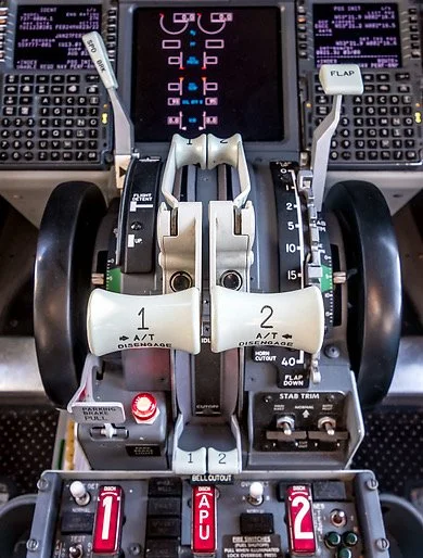
The auto brake is designed as a deceleration aid to slow an aircraft on landing or in rejected take off.  The rotary switch has four settings: RTO (rejected take off), 1, 2, 3 and MAX (maximum).  The brake can be disengaged by turning it to OFF, by activating the toe brakes, or by advancing the throttles; which deactivation method used depends upon the circumstances and pilot discretion.  

RTO and MAX provide similar braking power (3000 PSI).  1, 2, 3 and MAX provide an indication to the severity of braking that will be applied when the aircraft lands.   Often, but not always the airline will have a policy to what level of braking can or cannot be used; this is to either minimize aircraft wear and tear or to facilitate passenger comfort.  

In general, setting 1 and 2 are the norm with 3 being used for wet runways or very short runways.  MAX is very rarely used and when activated the braking potential is similar to that of a rejected take off; passenger comfort is jeopardized and it’s common for passenger items sitting on the cabin floor to move forward during a MAX braking operation.  This 'safety feature' is the reason why Boeing airframes have been designed so that the pilot must pull the auto brake knob before selecting MAX.

If a runway is very long and environmental conditions good, then a pilot may decide to not use auto brakes favoring manual braking.

The pressure in PSI applied to the auto brake and the applicable deceleration is a follows:

  • Auto brake setting 1 - 1250 PSI / 4 ft per second.

  • Auto brake setting 2 - 1500 PSI / 5 ft per second.

  • Auto brake setting 3 - 2000 PSI / 7.2 ft per second.

  • Auto brake setting MAX and RTO - 3000 PSI / 14 ft per second (above 80 knots) and 12 ft per second (below 80 knots).

To activate the auto brake it must be armed by selecting the appropriate setting using the auto brake selector knob (1, 2, 3 or MAX).  Furthermore, for the auto brake to engage the throttle thrust levers MUST BE in the idle position at touchdown.  If the auto brake has not been selected before landing, it can still be engaged providing the aircraft is travelling no slower than 60 knots.

The auto brakes can be disengaged by either pilot by applying manual braking or selection the auto brake selector knob to OFF.  Either action will cause the auto brake disarm annunciator to illuminate for 2 seconds before extinguishing.

Important Facet

It’s important to grasp that the 737 NG does not use the maximum braking power for a particular setting (maximum pressure), but rather the maximum programmed deceleration rate (predetermined deceleration rate).  You can only obtain maximum braking pressure using either RTO or when depressing the brake pedals.  Therefore, each setting (other than RTO) will produce a predetermined deceleration rate, independent of aircraft weight, runway length, type, slope and environmental conditions.

Auto Brake Disarm Annunciator

The auto brake disarm annunciator is coloured amber and illuminates when the following conditions are met:

  • Self test when RTO is selected on the ground.

  • A malfunction of the system (annunciator stays illuminated - takeoff prohibited)

  • Disarming the system by manual braking during an RTO or landing

  • Disarming the system by moving the speed brake lever from the UP position to the DOWN detente position.

  • If a landing is made with the selector knob set to RTO (not cycled through off).  If this occurs the auto brakes are not armed and will not engage.  The annunciator will remain illuminated

The annunciator will extinguish in the following conditions;

  • Auto brake logic is satisfied and auto brakes are in armed mode.

  • If the thrust levers are advanced during an RTO or landing ( 3 seciond delay is allowed after the aircraft has landed).

Personal Preference and Anti-skid

My preference for using auto brakes is, that when conditions are not ideal (shorter and wet runways, crosswinds) - I devote my attention to the use of rudder (for directional control) without concern for braking... the machine does the braking, and I take care of keeping the aircraft on the center-line...

Anti-skid automatically activates during all auto braking operations and is designed to give maximum efficiency to the brakes, preventing brakes from stopping the rotation of the wheel, thereby insuring maximum braking efficiency.

To read more on this subject navigate to: Rejected Takeoff (RTO) - Review and Procedures.

BELOW:  Photo montage of auto brake assembly.  Final conversion lower right picture - ready to install to MIP.

Photo montage of oem 737-500 auto brake.  Final conversion lower right picture - ready to install to MIP

737 Classic Flight Deck - Scrap to Home Flight Deck

oem 737 cl scraped flightdeck ©

I thought I'd post an image of how a flight deck appears after removal from the aircraft. This is a flight deck belonging to a Boeing 737 classic series which is the model previous to the 737 Next Generation.  Anything of value is slowly being removed for either scrap metal, repair and reuse, or for possible inclusion in a home flight deck. 

One aspect of flight deck building I enjoy is finding and using recycled parts.  Who said recycling cannot be enjoyable  :)

I've made this image full size, so if you want to see it in more detail click the image (image use courtesy of Tim ©).

Replacement Sidewalls for FDS MIP

I have mentioned in an earlier post concerning the Main Instrument Panel (MIP) from Flight Deck Solutions, that the unit was a little wobbly due to the thin metal used on the side-walls.  Whilst this is not a huge problem and certainly not an issue when the MIP is locke" into a shell, it does pose a minor issue when used without a shell.   Therefore, I decided to fabricate some replacement side stands for the MIP from 3mm aluminium sheet.

AutoCad was used to copy the dimensions of the original FDS sidewalls, and a lazer cutter cut the aluminium sheeting to the exact measurement.  Using a standard pipe bender, I bent the sides out at 45 degrees to allow slightly larger spacing for the rudder pedals.  I also increased the surface area of the metal which is used to attach the MIP to the platform, this ensures a more stable and secure attachment point for the MIP.  To replicate the MIP side-walls exactly, I TIG welded the narrow section that folds behind the stand.

Currently the aluminum is unpainted.  At some stage in the near future I'll either have the two units powder-coated in Boeing grey to match the colour of the MIP, or more than likely I'll prime and paint them myself.

The MIP is now very stable and does not wobble at all.

Digital Chronograph Running ProSim737 Software

The Main Instrument Panel (MIP), unless a special order is made, usually will not include a chronograph.  Depending upon the MIP manufacturer, the MIP may have a cut out for the chronograph, a facsimile of a chronograph or just a bezel. 

LEFT:   OEM chronograph used by America Airlines.  Nothing beats an OEM item, however, in this case conversion is difficult and a reproduction more cost effective.  Image courtesy of Micks737.

The Next Generation aircraft mostly use digital chronographs. The classic series airframes usually use (unless retrofitted) mechanical chronographs.

After Market Chronograph

There are several after-market chronographs that can be purchased.  SISMO Solicones produce a mechanical type that replicates the real world counterpart quite well, despite the awful orange-coloured backlighting.  Flight Illusion produces a quality instrument as does Flight Deck Solutions (FDS).  FDS replicate the digital chronograph. 

Chronographs are manufactured by several companies and not every chronograph looks identical, although their functionality is.  There are a few different styles available to an airline.  The main difference is in the number and shape of the buttons; round or rectangular.

No matter which type you decide, be prepared to shell out 250 plus Euro per chronograph; for an item rarely used it's quite a financial outlay.

Converting OEM Chronograph

Converting an OEM B737 mechanical chronometer is a valid option and the process of conversion is relatively straightforward.   However, finding a mechanical chronograph in operational order is difficult, as airlines frequently keep chronographs in service for as long as possible.  Converting a digital chronograph is also an option, however, the initial price of the item and then conversion make this an expensive exercise.  Add to this the fact that converting the chronograph, due to its internal digital electronics is very difficult (even if you use ARINC 429 protocol).

Another option is to use the virtual chronometer (Sim Avionics and ProSim737) and fabricate a reproduction bezel that overlays a small LCD screen.

ProSim737 Virtual Chronograph

Screen capture of ProSim737 chronograph.  ProSim737 have a Chronograph that can be used for the Captain and First Officer side of the MIP.  There are seevral version of the display that can be used

ProSim737 as part of their avionics suite have available a virtual chronometer.

The display used by ProSim737 is very crisp, the size is accurate (1:1 ratio), and the software allows complete functionality of the chronograph. 

To use the virtual version a small computer screen is needed on which is displayed the virtual chronograph.

Chronograph

A friend of mine indicated that he wanted to make a chronograph for the simulator and use the virtual ProSim737 display.  He also wanted to incorporate the four setting buttons and have them fully functional. 

The components needed to complete the project are:

  • A small TFT LCD screen (purchased from e-bay);

  • A standard Pokey interface card;

  • Several LEDS; and,

  • Four small tactile switches and electrical wire. 

I currently use an Main Instrument Panel (MIP) fabricated by Flight deck Solutions (FDS).  Therefore, the chronograph bezel used in this project was that supplied by FDS.

The screen used was 5.0" TFT LCD Module with a Dual AV / VGA Board 800x480 with a 40 Pin LED Backlight. 

The screen was small enough that it just covered the circular hole of the cut out in the FDS MIP.  The TFT LCD screen uses a standard VGA connector cable, 12 Volt power supply and a USB cable to connect the POKEY card to the computer.  

The holes in the box provide ventilation for the Pokeys card.  The only portion of the box that is visible from the front of the MIP is the bezel and four buttons

Two-part Fabrication

FDS supply with their MIP a bezel with four solid plastic but non-functional buttons.  The bezel does not support direct backlighting, nor does it have enough space for tactile switches or wiring. 

Therefore, the FDS bezel must be modified to accommodate the wiring for the switches and LED illuminated backlighting. The easiest way to approach this modification is to use a Dremel rotary tool with a 9902 Tungsten Carbide Cutter.

Place the bezel on a hard surface using a towel to avoid scratching and damaging the bezel.  Then, with 'surgical' accuracy and steady hands carve out several channels (groves) at the rear of the bezel.  The channels enable placement of the miniature tactile switches, small LEDS and wiring. 

Space is at a premium, and to gain addition real estate, the LEDS were shaved to remove excess material.  This enabled the LEDS to fit into the excavated groove on the bezel.  Be very careful when using the carbide cutter to not punch out onto the other side of the bezel. 

The four solid plastic front buttons on the bezel are carefully removed and small tactile switches attached (glued) to the rear of each of the buttons.   26/28 AWG wire is used to connect the tactile switches (using common ground leads) to a PoKeys interface card. 

The box is not seen as it's attached to the rear of the MIP.  My friend's humour - several warning signs suggesting that I not tamper with his creation :)

Box Fabrication

A small box needs to be fabricated to house the Pokey card.  The size of the box is controlled by the size of interface card used and the length and width of the LCD screen. 

A box is not required, however, it's a good idea as it illuminates the need to seal the LCD screen to illuminate dust ingress between the screen and overlying glass in the bezel. 

The material used to fabricate the box is plastic signage card (corflute); real estate agencies often use this type of sign.  The main advantage of this material is that it’s not difficult to find, is light in weight, and it's easy to cut, bend, and glue together with a glue gun.    

After the Pokey card is installed to the inside of the box, and the LCD screen attached to the front edge, the bezel needs to be secured to the front of the LCD screen.  The best method to attach the screen and bezel is to use either glue or tape. 

A hole will need to be made in the rear of the box to enable the fitment of the USB and VGA connectors.    Small holes punched into the side of the container ensure the LCD screen and PoKeys card do not overheat.  If you're concerned about heat buildup, a small computer style fan can easily be added to the box, but this does add complexity and is not necessary.  To conform to standard colours, the box is painted in Boeing grey.

LED Backlighting

Careful examination of the backlighting will show that the light coverage is not quite 100%.  There are two reasons as for this.

(i)    There is limited space behind the bezel to accommodate the wiring and the LEDS; and,

(ii)   The material that FDS has used to construct the bezel is opaque.  The only way to alleviate this is to replace the stock bezel with another made from a transparent material.

Important Point:

  • If you want to try and replicate the digital OEM chronograph as closely as possible, that the OEM version does not use backlighting.  Illumination of the front of the chronograph is by the MIP lighting.

Potential Problem

Depending on the MIP being used, there maybe space constraints that do not allow a 5 inch screen to be easily positioned.   If you're forced to use a smaller screen, the outcome will be that you may see the screen edges within the bezel.  For the most part this is not an issue, if you ensure the desktop display is set to black.  Remember, you are looking at the chronograph from a set distance (from the pilot seat) and not close up.

ProSim737 Virtual Chronograph (position and set-up)

This task is straightforward and follows the same method used to install and position the PFD, ND and EICAS displays.  

Open ProSim737’s avionics suite and select the virtual chronograph from the static gauges:  resize and position the display to ensure the chronograph conforms to the size of the bezel.  To configure the buttons on the bezel, so that ProSim737 recognizes them with the correct function, open the ProSim737 configuration screen and configure the appropriate buttons from the switches menu (config/switches).

The four functions the buttons are responsible for are:

(i)    Chronograph start;

(ii)    Set time and date;

(iii)   Expired Time (ET) and Reset; and,

(iv)   +- selection

NOTE:  The above functions differ slightly between the panel and the virtual chronograph in use.

Chronograph Operation and Additional Configuration

Captain-side CLOCK start button.  Connection between the clock button and the CHR button is made in the assignments page in ProSim737 (FDS MIP)

The chronograph can be initiated (started) by either depressing the CHR button on the top left of the clock, or by depressing the CLOCK button located on the glarewing of the MIP. 

Configuration

Connecting the CLOCK button to the chronograph start (CHR) function is straightforward.

Connect the two wires from the Captain-side clock button to the appropriate interface card and configure in the switches tab of ProSim737 (config/switches/CAPT CHR).

The same should be done with the First Officer side CLOCK button and chronograph, however, ensure you select the FO CHR function in switches to be done for the First Officer side chronometer if fitted.

If configured correctly, one press of the CLOCK button will start the chronograph, a second press will stop the chronograph, and a third press will reset the chronometer to zero.

After Market Chronograph

For those wanting to use an after market chronograph, SimWorld in Poland and Flight deck Solutions (FDS) in Canada produce high quality chronographs that can be dropped into the MIP with minimal required fabrication.

Video

A short video (filmed at night) showing the new chronograph running the virtual ProSim737 software.  Note that the chronograph displas is slightly smaller in the video to what it should be.  Adjusting the size of the display is done within the ProSim737 software.


Update

on 2020-06-18 03:27 by FLAPS 2 APPROACH

Another flight deck builder has also constructed a chronograph using similar methods.  His chronograph uses a different design that does not use a box. 

Update

on 2020-05-23 01:00 by FLAPS 2 APPROACH

In August 2019 this chronometer will be replaced.  The replacement will use a similar design, however, will not be encapsulated in a box that fits behind the MIP.  The new design will incorporate a å larger 5" TFT LCD screen that will enable more screen real estate for the chronograph.  The screen will be mounted directly to the rear of the MIP and the interface card will be adhered to the rear of the screen. 

The reason for changing the design is two-fold:

  1. The box is quite large, and the weight (although light weight) is heavy enough to cause the bezel to pull away from the MIP; and,

  2. Accessing the interface card is difficult (as it's inside the box).

An article explaining the process will form a new article.  The new chronograph very closely follows the design used by FlightDeck737.BE

Look Dad - No Mouse! - CP Flight PRO MCP & EFIS Installed

cp flight pro mcp

In an earlier Journal entry, I mentioned that the CP Flight main control panel (MCP) PRO version I had purchased last September (before I embarked on the B737 Project) appeared to be faulty.  For some reason the MCP would not register on the USB port of the computer.  After many hours of wasted time, I returned the unit to Italy for either repair or replacement.

Just before Easter I received a replacement unit.  Paolo from CP Flight had decided to replace the electronics. 

Installation & Configuration

Installation of the CPF software and configuration of this new unit worked first time without any problem whatsoever.  Configuring the MCP to operate with Sim Avionics was straightforward and required some basic changes to the Server.exe configuration files.  I also had to clone the TCP_Client.exe and MCP.exe folders and copy these to the main server computer that has FSX and the MCP installed.  These folders and files need to be installed on the same computer as the MCP software and hardware is installed to allow Sim Avionics to recognise the device.

Simulator Start-Up Procedure

So what happens now is that I start FSX on the main server computer, then once FSX is running and the flight is open, I activate the MCP.exe shortcut which turns on the CP Flight MCP.  The process of the MCP.exe been turned on triggers the TCP_Client.exe to open and search for it’s counterpart on the network.  Turning on the Sim-A Server.exe (via a batch start file located on the client computer) allows the programs to communicate and the appropriate software to open on the flight deck.

cp flight pro mcp backlighting

Backlighting – An Initial Mystery

To connect the CP Flight backlighting was a mystery until SIM-A support informed me that you can either select a check box within the SIM-A server display window which causes the backlighting to be permanently on, or create a FSUIPC offset to a switch using the aircraft’s storm lights for manual activation.  I choose the later and have the backlighting set to a toggle on a GoFlight module.  This will suffice as I do not as yet have an overhead installed.

My Opinion of the Unit

The CP Flight MCP and EFIS unit has been discussed many times in various reviews and on U-Tube; the consensus being that the majority of users are very happy with the product.

The unit is well made, is aesthetically pleasing, and works as it should.  The backlighting is very good and the green buttons that indicate whether a function is turned on or off are very visible.  The unit is quite light in weight compared with other MCPs on the market, so it must be installed solidly into the MIP to minimise movement when pushing buttons, etc.  The solenoid operated A/T switch is a nice change to the normal flick type switch and the use of replica DZUS fasteners is a nice touch.

CP Flight support is also beyond reproach.  Paolo is helpful, courteous, and attempts to find solutions when a problem is evident.  I had an issue with my first MCP and Paolo spent considerable time with me working through issues attempting to find a solution.  CP Flight is not a “buy and forget” you type of company.

cp flight mcp pro

Major Advantage

One of the major advantages in using products from CP Flight is the very easy connectivity with other CP Flight modules.  The CP Flight family of modules are connected together by a daisy chain system.  A 5 pin (5 pole) DIN cable connects each module to each other with the main power being supplied by the MCP and its external 6 Volt power pack.  Connection to the computer is via a single USB cable.  What this makes for is a very simple, clean and modular way of installation.  There are no cards to connect or to find homes for -  nor any messy wiring.

Caveat

The only caveat is that the size of the MCP and EFIS are not an exact 1:1 ratio to the OEM 737 MCP and EFIS.  The CP Flight instrument is slightly narrower that the OEM counterpart.  Whilst this is not a major issue, it does pose a slight problem if you are using an OEM MIP, or a MIP that is sized correctly to the real part. 

If you are using a MIP made by FDS, an additional bracket assembly is required, and even then there is a slight gap between the MIP and MCP unit.

This brings me to an interesting point.  Not all MIPS are the same size nor are they all an accurate 1:1 ratio.  CP Flight is used  exclusively with the MIP produced by Fly Engravity, so it stands to reason that the Fly Engravity MIP will fit the CP Flight products accurately.  if you are using another brand MIP, then it is best to check before hand to ensure that the CP Flight avionics will fit correctly.

Nice to Fly without a Mouse….

Whatever the difference in size, It’s very pleasing to be able to fly without a mouse and have something to fill the gaping hole in the MIP.  I’ve solved the issue of the spacing difference by cutting some thin acrylic to the appropriate size and painting it Boeing grey.  Once fitted, you barely notice the slight gap.  Sometimes you have to compromise...

Although this post is not a review, if pressed to give a rating it would be 8.5/10

Now that the MCP and Captain EFIS is fitted and working, I need to order an additional EFIS unit for the Flight Officer side. 

Next on the agenda will be to populate the avionics for the center pedestal. 

Update

on 2015-09-23 13:03 by FLAPS 2 APPROACH

The CP Flight connection issues that were occurring have been rectified by a software update from CP Flight. With connectivity reassured, I have ordered additional CP Flight panels (two ADF navigation radio panels and a rudder trim module).

First Officer EFIS

The second EFIS has arrived and has been installed into the simulator.  The ease of installation of CP Flight modules should not be taken lightly; they are literally plug and fly.  To install the second EFIS unit involved me connecting a 5 pin DIN cable from the Captain side EFIS to the FO EFIS unit.  I also had to move the small slider pin on the rear of the unit to reflect either captain or first officer.

I wish all panels were this easy to install.

Main Instrument Panel (MIP) by Flight Deck Solutions - Review


Overview

The main instrument panel (MIP) is arguably one of the most important pieces of equipment in a flight deck; it is around the MIP that everything revolves.  Every enthusiast wants the MIP to be athletically pleasing and as real to the OEM product as possible.  Depending upon the end use, the MIP may act as a skeleton from which to add OEM parts, or standalone accommodating reproduction parts.

There are several companies that produce MIPS and each has its nuances.  After extensive research, Flight Deck Solutions (FDS) in Canada was commissioned to supply the MIP.

Note that in this review, reference is made to the term OEM which is an acronym for Original Equipment Manufacturer (aka real Boeing 737 aviation part).

The image above is the Duel Seat Training Device offered by Flight Deck Solutions (image courtesy and copyright FDS).

Information - Not Pretty Pictures

This post is not intended to be an exhaustive review of the FDS MIP or the parts attached to the MIP.  Rather, the intent of the review is to provide adequate information for enthusiasts to make an intelligent decision to which MIP to purchase.  

Furthermore, it is important to understand that all reproduction simulator parts are exactly that - a reproduction or facsimile of a real part.  Often reproduction parts are not to scale and have subtle differences to the real item.  Whether this is important is at your discretion and very much depends upon whether you intend to use OEM parts or solely reproduction parts.

To view images of the MIP, navigate to the image gallery

Interface cards have not been discussed for two reasons.  First, there are several differing types of cards that can be used, and second, Integrated Cockpit Systems (ICS) units come ready-made with all wiring and interface cards installed. 

ICS and Options

FDS provide two options when purchasing their MIP - naked (do it yourself) or as an integrated cockpit system (ICS).

The ICS route was chosen because of time constraints; by eliminated the task of wiring and soldering a multitude of interrelated electronic parts together, it would allow more time to concentrate on converting real aircraft parts to use in the simulator.  At the forefront of the B737 project, the MIP was to be a skeleton from which to hang OEM parts.

The MIP consists of two sections; the main instrument display including the lower display and glare shields (eyebrows), and the base structure incorporating the CDU mounting area, lower display and stand.

FDS landing gear lever is a good facsimile of the real lever; however, the lever does not recess between the two half moons.  Nor is the red trigger spring-loaded as in the OEM mechanism.  Despite these aesthetic shortfalls, the landing gear functions well.  The leather skirt is a step in the right direction concerning authenticity

UPPER MIP (Instrument Panel, Glareshield and Lower Panel/Kick Stand)

The panel is made from CNC machined acrylic and the glare shield from injection molded plastic. The panel and glare shields have been attached by screws to a light-weight powder coated aluminum frame which incorporates a 4 inch wide shelf on the rear side. 

The cut-out lettering, which allows the lettering to be back-lit, is very crisp with well defined edges.

The panel has been professionally painted in Boeing grey.  Although the panel is made from acrylic, the use of high quality flat paint removes the sheen that acrylic is renowned for.  In comparison to other plastic-looking panels on the market, the colour and appearance is very true to form.  It looks 'almost; like the OEM panel. and matches the real aircraft parts very well.  Furthermore, FDS apply the paint in several thin layers which makes the coating very resistant to chipping and scratching.

Switches have been mounted in the correct locations and the wiring from these switches has been secured within a wiring lumen or by plastic cable ties.  The switches and knobs replicate those of the real aircraft and have the correct feel, although the general purpose knobs (GPK) do not replicate the exact appearance of the OEM knob.  Where a panel has not been included (not stock B737 configurations) a blanking panel has been fitted.

The soldering work and connections on all switches are excellent; it is more than obvious that the person who did the soldering work is a professional with many years experience.

The gear lever is sturdy and feels solid.  To engage the landing gear, the lever must be pulled out of its recess and pushed up or down.  The detail to the lever is excellent and installation includes the correct-looking fiber sleeve.  The mechanism does not have the spring-loaded trigger; the trigger is a solid cast item attached to the lever.

Annunciator lights (six packs) and various warning lights are all functional; however, pale comparison to OEM parts and other high-end reproductions; they appear 'cheesy'.  The glare shield is strong textured ABS plastic and wraps over the top of the MIP.  A correctly sized chart pocket is screwed to the top of the shield.  The two glares either side of the MIP on the Captain and First Officer side are painted MDF wood and although not have a negative appearance they do not replicate the appearance of the OEM glare which is made from textured foam plastic.

The shelf system, located behind the main instrument panel, is an excellent idea.  The shelf, in addition to providing an area for the FDS monitor stands to be mounted, is a good platform to mount various cards, speakers and other items that may be required.

The FDS bracket, a novel design to hold the display units firmly in place.  The display unit bezel is made from plastic and does not hinge outwards as the real bezel does.  the knobs on the ISFD are not replicated

The lower display modules, which are mounted to the lower area of main panel, are installed using normal Phillips-head screws.  In a real B737, panels and modules are usually secured using DZUS  fasteners or skirted screws.  It would have been a nice touch to have replicated the use of DZUS fasteners on the panels in the lower kick stand.

Display Unit Covers

The protective displays that the computer monitor screens (display units) are made from 1.5 mm thick perspex.  I have found the perspex to be very reflective - especially so if the simulator is located in a well-illuminated room.    

Integrated Back-Lighting (IBL)

Integrated back Lighting (IBL) is the name FDS has coined to refer to their proprietary design in which FDS utilise aircraft bulbs rather than LEDs.  IBL is supplied to illuminate the back lighting in all FDS panels and modules.  

One of the main advantages of a bulb in contrast to that of a LED is the throw of the light and the colour temperature.  The area of coverage from bulbs is relatively even, where the coverage by an LED is more pinpoint and uneven.   The only way to achieve a similar light coverage to bulbs using LEDs is to use several LEDS mounted in close proximity to each other. 

One area that the use of bulbs  excels is the rear illumination of the stencil-cut lettering on the MIP.  Bulbs will completely illuminate the stencil cut-outs where LED lighting will often only illuminate part of the stencil cut-out (unless there are several LEDs).

Bulbs and LEDs have different colour temperatures.  A bulb transmits a warm colour (soft orange hue) whereby a LED transmits a cooler colour that appears more blue in comparison.

All Boeing airframes, with the exception of the newest airframes utilise 5 and 28 volt incandescent bulbs.

The only downside of IBL (if there is one) is that the bulbs generate quite a bit of heat.  The life of a bulb is also less than a LED.

Ground Proximity Panel showing use of Phillips head screws rather than the more usual DZUS fasteners

What the MIP Lacks

The non-use of DZUS fasteners in the lower panel (kick stand) and the failure to use skirted screws has been mentioned.

Stand-by instruments and clocks are not included.  FSD supply a stenciled backing card which is mounted behind the perspex to mimic the look of the yaw dampener, brake pressure, clock and flaps gauge. 

Considering the purchase price of a MIP, and considering the importance of a working flaps gauge, an operational analogue flaps gauge should be a stock item.  

The avionics suite (Sim Avionics) can display virtual stand-by instruments id required.

The speed reference panel and knobs are not functional. The knobs used in the speed reference panel do not replicate the OEM knobs used in the B737; the real aircraft uses double rotary encoder knobs. As with the flaps gauge, these knobs should be functional and, at least shoe some resemblance to the real part.

Software - Interface IT

The software to interface the MIP (InterfaceIT) seems to be well designed and robust.  It does require a learning curve to become proficent with the software, but once proficent the siftware is logical in layout and use.  Installation of the IT software is straightforward.

Additionally, there is a direct link between InterfaceIT and Sim Avionics which makes internal configuration and programming very easy.

Flight Avionics Suite

Duel Seat Training Devices (DSTD) and MIPS configured by Flight Deck Solutions use Sim Avionics as their flight avionics suite.  After you receive your MIP, FDS staff will e-mail to you a file which you import into InterfaceIT.  This file holds the data assignments for the MIP buttons and switches.

Although FDS recommend Sim Avionics, there is no obligation to use this software; the MIP will operate with whatever software you choose.  A seperate post will deal with a review of Sim Avionics.

The rear shelf located behind the MIP and the propriety bracket used to hold the display units (computer screens) firmly in place.  The bracket works exceptionally well and the shelf is very sturdy

Lower Base Structure

The base structure comprises the lower section of the MIP and includes the CDU bay structure and lower display screen.  The structure is made from aluminum which has been professionally powder coated in Boeing grey. 

As with the upper section of the MIP, the attention to detail is obvious.  There are no sharp edges on the CDU bay structure, nor are there gaps where panels attach together.  Screws match their holes correctly.

The DZUS rails that line the internal section of the CDU bay marry perfectly with the DZUS fasteners used to secure the Control Display Unit (CDU/FMC) to the rails.    It does not matter whether a reproduction or OEM CDU unit is used as both will fit perfectly.

The lower display screen, which fits between the two gaps in which the CDUs reside, is identical in shape and manufacture to the upper display unit bezels.  Unlike the three upper bezels in which a standard computer monitor can be mounted, the lower screen requires a smaller monitor which is not an off the shelf item.

clock panel showing backlighting during the day. the fabrication of this panel and button is very good as is the stenciling

Dimensions, 1:1 ratio and Using OEM Parts

The ability of a manufacturer to produce a MIP that is the correct 1:1 ratio to the real item cannot be underestimated.  If an enthusiast is intending to only use instruments and panels produced by that manufacturer, then any size disparity is probably unnoticeable and probably not that important.  However, if OEM parts are to replace reproduction parts, then the base sizing become crucial to the correct and easy fitment of an OEM part.  In this area, the FDS MIP has some shortfalls.

The MIP has a number of holes and gaps that parts reside, for example for the AFDS and flaps gauge.  If the holes are incorrectly matched to the OEM part, either a new panel (aluminum backing plate) will need to be engineered and painted, or the hole may need to be enlarged.  Although enlarging a hole in a MIP is straightforward, the opposite is problematic and requires the design of a new panel.

Unfortunately, many of the holes in the FDS MIP do not correspond to the correct size when fitting OEM parts.  For example, the holes that the AFDS units reside must to be enlarged considerably to enable OEM AFDS units to be fitted.  Likewise, the holes to fit the annunciators need to be enlarged.  The hole that the flaps gauge is housed is far too large and a new panel needs to be designed to gt an OEM flaps gauge.

Detail of the angled shelf used to accommodate the I/O cards.  The multi-voltage computer power supply can also be seen mounted behind the perforated vents.  The terminal block caters to 5 and 12 volts.  The interface card is the FDS SYS card which comes standard with the ICS MIP

Power, System I/O Cards and Cabling

A multi-voltage computer power pack is used to power the MIP and has been mounted at the rear of the lower base structure. 

The position chosen is well suited to internal wiring and allows easy access should a problem develop.

An angled shelf has been engineered to fit immediately behind the CDU bay.  The design of the shelf is intended as an area on which to mount the various interface cards required to operate the simulator.

The interface cards required to operate the MIP have been secured to the angled shelf and all wiring has been expertly soldered or attached via solid electrical clips.  Cabling and connections are of the highest quality.  Each of the wires that are connected to the SYS board has been tagged with a plastic tag which indicates their function; a good idea if you need to change something at a later date or troubleshoot a particular problem.

There has been no compromises with regard to how the staff at FDS wired the MIP - it is beyond reproach.

3mm replacement side stand.  The replacement stand inhibits any movement of the MIP as the structure is not (at the moment) installed within a shell

Base structure (side stands)

The base structure (stand) has been designed to be mounted either directly to a base platform.  The mounting points are numerous holes along the lower angled edge of the stand.  A concern was that the structure would wobble, as it is quite high and made from light-weight aluminum. 

These concerns were short-lived; once each attachment point was secured with a screw the assembly was quite solid.  This said, if you energetically engage the landing gear lever, there is a very slight movement in the upper area of the MIP.  If you are mounting the MIP into a cockpit surround, any movement will cease as it will be attached to the outer skin of the shell.

To counteract any movement, it is a relatively easy matter to fabricate two replacement side stands from a thicker sheet of aluminum (3-5mm).  This will guarantee that there will be no movement when manipulating knobs, the landing gear, etc.

Navigate to this post to read about the replacement side walls.

Communication, Support and Delivery

Communication with FDS was excellent.  E-mails were always answered in a timely manner and Peter and Steven Cos are very professional in their approach. I was continually kept in the loop regarding construction and shipping.

Support if and when required is either via a dedicated forum, e-mail, or if necessary by telephone.  Peter and Steve Cos very approachable and helpful and their support is second to none.  I would go so far as to say that the support that FDS provides cannot be matched.

It is important to note that Flight Deck Solutions is not a mail order company with products in storage waiting to be shipped; products are assembled to order.  This means that often there is a timely wait until you receive your shipment.

The MIP I had delivered to Australia was packed in and attached (screwed) to the floor of a large wooden crate.  It arrived undamaged.

Quick List - Pros and Cons

PROS

  • Well designed & constructed

  • Excellent workmanship (metalwork and wiring)

  • Realistic and highly effective Integrated Back-Lighting (IBL)

  • Good functionality

  • Very clean appearance - wiring and cards favorably positioned

  • 1:1 (or as near possible) to the real MIP (exception if using OEM gauges)

  • Moderate to high attention to detail

  • Robust & functional software (InterfaceIT) if using Sim Avionics avionics suite

  • Excellent paint quality (several layers of paint) that resists chipping and scratching

  • Outstanding support - the best in the industry

CONS

  • No analogue flaps gauge, other than virtual version (rectified by spending more money)

  • No stand-by instruments or clock (rectified by spending more money)

  • Non use of DZUS fasteners in lower panels above 'kick stand' (small things do make a difference)

  • RMI knobs are very low quality

  • Speed reference knobs are very low quality & do not replicate OEM B737 knobs

  • Landing gear lever does not recess behind shield when in down position

  • Landing gear does not utilise the spring trigger as in the real aircraft

  • Section between upper and lower MIP (kick-stand) is not the correct shape.  It should be rounded and not be an angled piece of aluminum

  • Display unit covers are very reflective (easily rectified- remove or replace them with tinted displays)

  • Slightly inaccurate General Purpose Knobs (GPK) - poor stenciling on knobs

  • The MIP is not completely 1:1 and if using OEM parts, some engineering is required to fit OEM parts

  • The MIP is not an exact reproduction and artistic license has been taken in some areas (for example, the section between the upper and lower MIP (kick-stand).  The MIP also lacks various screws and fasteners seen on the OEM MIP

Important Point:

  • If you are intending to add OEM panels, switches and knobs to the FDS MIP, be aware that many of the panels do not fit the FDS MIP.  This is because the MIP frame is not exactly 1:1 with the OEM equivalent.  In some instances (such as when retrofitting panels) the MIP is out by up to 1 cm.  Also be aware that OEM korrys, flaps gauges and some of other avionics will not fit into the precut holes.  You will need to either enlarge the hole or make it smaller.

FDS GPK with backlighting. The knob has a slightly different shape to OEM knobs. the adjustable propriety backlighting is perfect

General Purpose Knobs (GPK)

The GPKs are of high quality, however fail in a number of areas.

The black line is a manually applied adhesive which depending upon which knob you are inspecting, may or may not be quite straight.  Being adhesive, with time the transfer lifts, especially at the ends.  The translucent line between the black outer lines is not as bright as that observed in the real aircraft.  Not all knobs have the transfers correctly aligned.

poor quality lower kickstand knobs. gpk showing excess plastic from manufacture process

The knobs are the incorrect shape and the grub screws are located in the wrong position on the knob.  The knob also does not have an inside metal shroud (circular retainer).  The retainer increases the longevity of the knob as it stops the acrylic from being worn down over time with continual use.

The knobs on the lower kick stand are also of poor quality bearing only a little resemblance to the OEM knobs

The knobs serve a function, but for the price of the MIP, knobs that reflect a more accurate representation would have been appreciated.

fds adf knob. WHY EVEN HAVE THIS AS IT IS NOTHING LIKE THE OEM RMI KNOB

RMI Selector Knobs

The knobs are made from acrylic with a transfer attached.  The knob has no functionality and is attached to the MIP in a recessed hole.  The RMI knob bears no resemblance to the OEM knob and is very poor quality.

Speed reference knobs are very low quality

Speed Reference Knobs (SRK)

The speed reference knobs supplied with the FDS MIP bear no resemblance to the OEM knobs. The OEM knob should be a double rotary encoder knob.  There has been no attempt to replicate this type of knob.

Used Fuel Reset Switch

FDS have used a normal two-way toggle which is incorrect.  There is no similarity to the OEM used fuel reset switch.  The OEM toggle has a large bulbous head and is a specially-designed three-way toggle.

fds Boeing warning system. although functional the displays fall short of replicating the oem items

Autopilot Flight Director System (AFDS) 

Although not an exact replica of the OEM part, FDS has done a good job replicating the functionality of the AFDS.  Unfortunately, if you wish to replace the FDS unit with an OEM AFDS unit, the hole in the backing plate that attaches to the MIP will need to be enlarged considerably to allow correct fitting of the OEM component.

Boeing Warning System (six packs)

Compared to the OEM counterpart, FDS’s offering is lacking. The two warning buttons can be depressed very easily where the OEM buttons are quite firm requiring a good push. The six packs work quite well, however, lack adequate light coverage when a warning is displayed.

Annunciators (korry condition lights)

The FDS MIP uses LED reproduction annunciators (korrys).  The LEDS are illuminated by two 5 volt LED lights which do not provide complete light coverage across the lens plate.  The brightness of the LEDS is also not as bright as the OEM annunciators. 

Furthermore, the hole in the MIP that the korrys reside is a tad on the small side; therefore, if you are intending to replace the reproduction korrys with Original Equipment Manufacture (OEM) annunciators, you will need to engineer the hole to a larger size.  This is unfortunate as a MIP should be manufactured 1:1 to allow reproduction parts to be replaced with OEM parts.

on the oem landing gear the red trigger sits flush with the two half moons

Landing Gear Lever

The landing gear lever requires more explanation.

In the real B737-800 NG the landing gear handle sits closer toward the main instrument panel.  The half circular shield is designed so that the red-coloured gear trigger sits between the two half moon shields when the lever is in the DOWN position.  In the FDS version, the trigger sits too far out from the front of the MIP and the trigger is not protected by the two shields.

Furthermore, the trigger is not spring-loaded as in the OEM mechanism; it is a solid piece of metal.

Lights Test / DIM Switch

A normal two-way momentary toggle is used which is incorrect.  The OEM switch is a three way non-momentary switch which allows the switch to be placed in any one of three positions.  The OEM toggle is also large than a standard toggle switch.

Final Call

The MIP is well made and has been finished with obvious care; parts line up correctly, screw heads have not been burred and paint not chipped.  Wiring, soldering, parts, switches, paint, colour, rotaries, blanking panels and display frames are of the highest quality.  It is obvious you are dealing with a premium product that provides an very good facsimile of a 737-800 instrument panel.

Downside is the lack of any hard-wired gauges, poor quality speed reference and general purpose knobs, lack of DZUS in lower panels, no flaps gauge, and a wrongly positioned landing gear lever (when in the down position).  Another issue is that the MIP is not 1:1 with its OEM counterpart, nor is it a 100% accurate rendition of an OEM MIP. 

This said, for many enthusiasts this will not be an issue as the differences are minor.  If you intend to use OEM parts then some parts of the MIP will need to be fabricated to enable the real parts to fit snugly into the MIP.

Depending upon your end use - a MIP with reproduction gauges, or a MIP skeleton to hang OEM parts - your views will alter.  Certainly, the FDS MIP is not to be discounted as a premium product; it is a pity that FDS did not take a few extra steps to make this MIP the 'Queen of the crop.

The closest rival to the FDS MIP is the MIP manufactured by Fly Engravity and SimWorld.  Other MIPS are available from other companies, but the FDS MIP, although lacking in some areas is superior in many ways. 

Rating is 7.5/10

Please note that this review is my opinion only..  Furthermore, note the date of the review.   Flight Deck Solutions may have updated their MIP after this review has been published. 

  • Thanks to Peter Cos, Flight Deck Solutions for allowing the use of the front image.

NOTE:  Before taking what you read as gospel, check the FDS website in case these shortcomings have been rectified since this post was published.

Installing Display Monitors to Flight Deck Solutions MIP

fds mip. the mip has a very handy shelf at the rear. propriety angled monitor display stands are very helpful in securing monitors to the rear of the mip. When positioned correctly, the bracket is tightened with Allen bolts

Over Christmas, I mounted the display monitors to the MIP.  Although an easy task, it’s a bit fiddly trying to match up the monitor display with the perspex panel in the MIP.

Monitor Display Stand

double sided cushion tape is used to frame each monitor. this avoids dust and stray light from entering the side of the monitor

I’m using two Viewsonic 19 inch wide screen monitors for the primary flight display and navigation display and an older HP 15 inch monitor for the centre EICAS.  After dismantling the plastic covers from the displays (how these clip together without screws only the Chinese can manage), I cleaned each screen before fitting to the rear of the MIP.  I’m glad I purchased from Flight Deck Solutions the monitor display holders, which make the attachment of the displays so much easier.  It’s only a matter of acquiring the correct position of the display, then moving the cradle forward, back, left or right and tightening the Allen screws.  It's a simple install and adjustment, but as mentioned, does take some time to ensure the screens are mounted in the correct position.

Concerned About Dust

I was concerned that dust and back light may stray onto the monitor display between the display and MIP Perspex.  This is because the lower side of the monitor does not sit entirely flush to the perspex.  I solved this potential issue by adding to each monitor frame a layer of adhesive padding.  The padding also provides a soft interface between the front of the display and the MIP.  The padding strips are readily available at hardware outlets and often are used in the fitting of glass shower screens.

I couldn't find black coloured adhesive , therefore, to minimise the chance of seeing the white adhesive, I used a permanent marker pen to colour in the inner edge.

One important thing to note when installing the displays is to make sure they are orientated the right way!  I installed them upside down – maybe because I live in Australia :)

Clean Up Wiring

Next on the list is to clean up the wiring from the MIP to the two computers.  As you can image there are a lot of wires, USB cables, power and monitor cables.  I used a wiring loom to keep things somewhat tidy; I dislike “rat-nest” wiring. 

What's Next?

After this, it’s onto installing Sim Avionics and other FDS software to get the MIP operational with full functionality. 

Main Instrument Panel (MIP) Arrived - Updated Progress

fds mip in a large crate in trailer

At last, a phone call from DHL Freight Forwarding has advised me that the Main Instrument Panel (MIP) I ordered from Flight Deck Solutions (FDS) in Canada, in August, has finally arrived and is ready for pick up.

This means that the next phase -  the actual construction of a working sim can begin in earnest. 

The box that is used to transport the MIP is large as the MIP is prefabricated. When you order a MIP from Flight Deck Solutions you can choose to have it flat packed or prefabricated; I choose the later.

To recap on what has been acheived since August 2010:

  • Research, ordering and implementation of project

  • OEM 737-300 throttle quadrant overhauled and converted to operational use with flight simulator (FSX) & troubleshooting completed

  • Several phidget cards installed and calibrated to correct operation

  • 737-300 center pedestal overhauled and ready to populate with avionics modules

  • Platform base constructed and painted

  • Weber Captain and First Officer seats procured and overhauled to working order

  • ACE yoke & column purchased, calibrated and flight tested

  • OEM 737-500 yokes and columns procured and awaiting conversion to operational use in flight simulator (March 2012)

  • Computers purchased, configured and networked

  • MCP and EFIS (pro version) purchased from CP Flight in Italy

  • Avionics modules (various) purchased for installation to avionics bay and evaluation

  • Main Instrument Panel (MIP) wired and prepared for installation and evaluation

  • Various genuine B737 instruments procured and awaiting conversion to operational use in flight simulator (in due course)

  • various software add on packages purchased and evaluated

Therefore, everything appears to be ‘green for go’.

Boeing Style 737 Clock

737 cl clock installed to mip. a future project will be wiring the clock for operation. at the moment 5 volts backlighting is connected

Whilst waiting for the Main Instrument Panel (MIP) to arrive from Flight Deck Solutions (there has been a delay in fabrication), I came across this OEM 737 clock for auction on e-bay.  The clock has been removed from an American Fed Ex aircraft and has been serviced to new condition.  The price I paid was very reasonable and my thoughts were it would make a very nice addition to the MIP to replace the stenciled clock or reproduction clock on the First officer side.

I'd like to try and get the clock working with the simulator, and will look at doing this sometime in the future.  At the moment I will contend with the fact that it's a nice looking 737 style clock that adds to the aesthetics of the MIP on the First Officer side.

OEM components are generally inexpensive and often less than the price of reproduction items, and while conversion of an OEM part can be difficult for the technologically challenged, it is not impossible.

If you are seeking realism, then OEM components provide a more tangible feeling to what is in effect a reproduction flightdeck.

737-800 Clock

This clock is not what most Next Generation aircraft have installed.  The Next Generation usually has a digital chronograph.  I am using a chronograph on the Captain-side. This style of clock is more readily observed in a 737 classic airframe. 

I intend to fit this clock to the First Officer side of the MIP.  The Captain side will have a standard style Next Generation chronograph fitted.

Update

on 2016-03-01 12:58 by FLAPS 2 APPROACH

I've received several e-mails asking where I found this clock and how much I paid for it. 

I discovered the clock on e-bay and the price was a tad over $100.00 USD with freight.  The freight paid was most of this amount!  A fair price, in my opinion, for a serviceable 737 style clock.