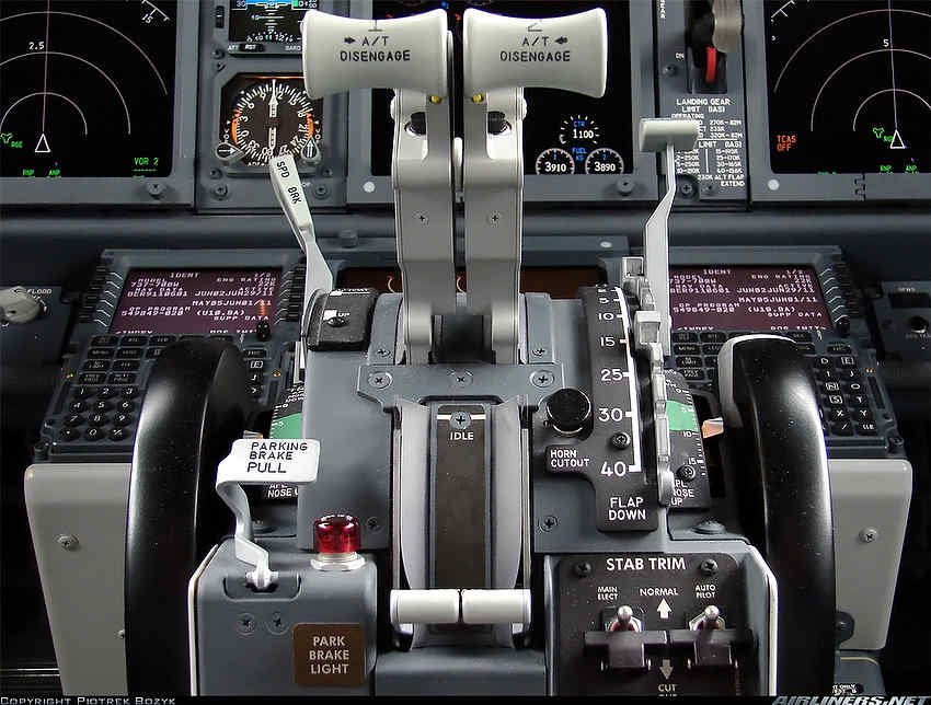
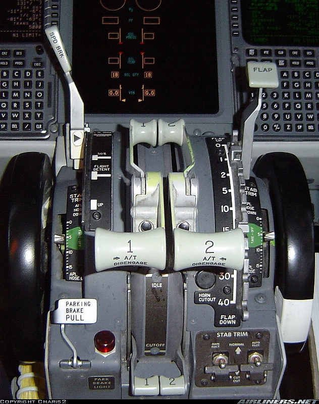
Assembly of Forward Overhead Panel

Forward overhead using OEM parts

Construction of the simulator began in 2011.  It is now 2016 and I am perplexed to why the build has taken so long to complete.   Of course, opting to try and use OEM (Original Equipment Manufacture) parts whenever possible has added significant time to the project - especially the procurement of parts.

Most of the parts that make up the forward overhead have now been obtained and assembly of the components is well advanced.   Very soon the wiring from the panels to the Phidgets cards will begin.  This will be followed by several hours of testing to check correct functionality and to ensure perfect harmony between components and systems. 

A basic frame has been constructed to enable the overhead to be easily positioned to enable the wiring to be done with a little more ease.  After the forward overhead is completed, work on the aft overhead will commence.  Rome, it seems, was not built in a day.

Certainly, completion of the forward overhead will be the major project over the next few months.

Knobs Aren't Knobs - Striving for the Perfect Knob

The real item – a Boeing Type 1 General Purpose Knob (GPK) and issue packet.  There can be nothing more superior to an OEM part, but be prepared to shell out a lot of clams

In Australia during the early 1980’s there was a slogan ‘Oils Ain't Oils’ which was used by the Castrol Oil Company.   The meaning was simple – their oil was better than oil sold by their competitors.  Similarly, the term ‘Knobs aren’t Knobs’, can be coined when we discuss the manufacture of reproduction knobs; there are the very good, the bad, and the downright ugly.

Boeing Knobs

As a primer, there are several knob styles used on the Main Instrument Panel, forward and aft overhead, various avionics panels, and the side walls in the 737-800 Next Generation. 

If you search the Internet you will discover that there are several manufacturers of reproduction parts that claim their knobs and switches are exactly identical to the OEM knobs used on Boeing aircraft – don’t believe them, as more often than not they are only close facsimiles.

In this article, I will primarily refer to the General Purpose Knobs (GPK) which reside for the most part on the Main Instrument Panel (MIP).  Boeing call these knobs Boeing Type 1 knobs.

oem 737 -800 next generation knob. note different location of set screw. knob used on overhead

Why Original Equipment Manufacturer (OEM) Knobs Are Expensive

Knobs are expensive, but there are reasons, be they not be very good ones.  

The average Boeing style knob is made from painted clear acrylic resin with a metal insert. On a production basis, the materials involved in their manufacture are minimal, so why do OEM knobs cost so much…   Read on.

There are two manufacturers that have long-term contracts to manufacture and supply Boeing and Airbus with various knobs, and both these companies have a policy to keep the prices set at an artificially high level.

Not all flight decks are identical, and the requirements of some airlines and cockpits are such that they require knobs that are unique to that aircraft model; therefore, the product run for knobs for this airframe will be relatively low, meaning that to make a profit the company must charge an inordinate amount of money to cover the initial design and production costs.

A high-end plastic moulding machine is used to produce a knob, and while there is nothing fancy about this type of technology and the process is automated, each knob still requires additional work after production.  This work is usually done by hand.

Cross section of a Boeing Type 1 General Purpose Knob

Once a knob has been produced, it must be hand striped and finished individually to produce a knob that is translucent and meets very strict quality assurance standards.  Hand striping is a complex, time consuming task. 

Additionally, each knob must undergo a relatively complex paint spraying procedure which includes several coats of primer and paint, and a final clear protective coating.  Spray too much paint and the translucent area (called the pointer) inside the twin parallel lines will not transmit light correctly.  Spray too little paint and the knob can suffer from light bleed.  There is a fine line during production when it is easy to ruin an otherwise good knob with a coat of thickly applied paint. 

Finally, any part made for and used by the aviation industry must undergo rigorous quality assurance, and be tested to be certified by the countries Aviation Authority.  Certifying a commercial part is not straightforward and the process of certification takes considerable time and expense.  This expense is passed onto the customer.

Often disregarded during the manufacture of reproduction knobs is the inner metal sleeve.  The sleeve protects the material from being worn out from continual use

Replicating Knobs - OEM Verses Reproduction

It’s not an easy process to replicate a knob to a level that is indiscernible from the real item.  Aside from the design and manufacture of the knob, there are several other aspects that need to be considered: functionality, painting, backlighting, robustness and appearance to name but a few. 

Backlighting and Translucency

To enable the knob to be back lit calls for the knob to be made from a translucent material.  Unfortunately many reproduction knobs fall short in this area as they are made from an opaque material.

The knob must also be painted in the correct colour, and have several coats of paint applied in addition to a final protective layer.  The protective layer safeguards against the paint flaking or peeling from the knob during normal use.  In the photograph below, you can see where extended use has begun to wear away part of the knob's paint work revealing the base material.

Detail of the grip and metal set screw.  The set screw is important as it enables the knob to be secured against the shaft of the rotary.  This knob previously was used in a Boeing 737-500

Set Screws and Metal Inserts

Often lacking in reproduction knobs is a solid metal set screw (grub screw).

The task of the set screw to secure the knob against the shaft of the rotary so that when you  turn/twist the knob it does not rotate freely around the shaft.  Plastic set screws can be easily worn away causing the knob to freely rotate on the shaft of the rotary encoder. 

The position of the set screws on the knob also deserves attention.  Correctly positioned set screws will minimize the chance of rotational stress on the shaft when the knob is turned.

Of equal concern is the hole on the underside of the knob where the rotary shaft is inserted.  The hole should be sheathed in metal.  This will increase the knob’s service life.  If the hole does not have a metal sheath, it will eventually suffer from wear (disambiguation) caused by the knob being continually being turned on its axis.   Finally, the knob must function (turn/twist) exactly as it does in the real aircraft.

Reproduction knobs may fail in several areas:

(i)    The knob has various flaws ranging from injection holes in the molded plastic to being the incorrect size or made from an inferior plastic material;

(ii)    The knob does not use metal set screws, and the set screws are not located in the correct position on the knob;

(iii)    The knob has a poorly applied decal that does not replicate the double black line on Next Generation General Purpose Knobs.  The adhesive may not be aligned correctly and may peel away from the knob;

(iv)    The knob is made from a material that does not have the ability to transfer light (translucent pointer);

(v)    The knob does not appear identical in shape to the OEM part (straight edge rather than curved);

(vi)    The paint is poorly applied to the knob and peels off.  OEM knobs have several thin coats of paint followed by hard clear coating of lacquer to ensure a long service life;

(vii)    The colour (hue) of the knob does not match the same hue of the OEM product; and,

(viii)    The circular hole in the rear of the knob, that connects with the shaft of the rotary encoder does not have inner metal sleeve.  

The time it takes to manufacture a knob is time consuming, and to produce a quality product, there must be a high level of quality assurance throughout the manufacturing process.

Older Classic-style Knobs

It's common knowledge that many parts from the classic series airframe (300 through 500) are very similar, if not identical to the parts used in the Next Generation airframe.  Unfortunately, while some knobs are identical most are not.

The knobs may function identically and be similarly designed and shaped, but their appearance differs.  Knobs used in the Next Generation sport a twin black-coloured line that abuts a translucent central line called the pointer, classic series knobs have only a central white line.

Rotary Encoders

Although not part of the knob, the rotary encoder that the knob is attached deserves mention.

A fallacy often quoted is that an OEM knob will feel much firmer than a reproduction - this is not quite true.  Whilst it is true that an OEM knob does has a certain tactile feel, more often than knot the firmness is caused by the rotary that the knob is attached to.

Low-end rotary encoders that are designed for the toy market are flimsy, have a plastic shaft, and are easy to turn.  In contrast, rotaries made for the commercial market are made from stainless steel and are firmer to turn.

Also, low end rotaries and knobs are made from plastic and with continual use the plastic will wear out prematurely resulting in the knob becoming loose.

Many reproduction knobs fit the bill, and for the most part look and feel as they should.   t's easy to criticize the injected plastic being a little uneven along the edge, but this is unseen unless you are using a magnifying glass

Final Call

Whether you use reproduction or OEM knobs in your simulator is a personal choice; It doesn't play a huge part in the operation of a simulator.  After all, the knobs on a flight deck are exactly that – knobs.  No one will know you have used a reproduction knob (unless low end reproductions have been chosen).

However, the benefit of using a real aircraft part is that there is no second guessing or searching for a superior-produced knob.  Nor is there concern to whether the paint is the correct colour and shade, or the knob is the correct shape and design – it is a real aircraft part and it is what it is.  But, using OEM knobs does have a major set-back - the amount of money that must be outlaid.  

But, second-hand OEM NG style knobs are not easy to find and often there is little choice but to choose ‘the best of the second best’.

BRT / DIM Functionality - Lights Test Switch

Lights Test switch.  The three way switch located on the Main Instrument Panel (MIP) Captain-side is used to toggle the intensity of connected annunciators.  The panel label reads TEST, BRT and DIM.  The switch in the photograph is an OEM switch which has been retrofitted to a Flight Deck Solutions (FDS) MIP

The annunciators in the Boeing 737 are very bright when illuminated, and the reason for the high intensity is justified - the designers want to ensure that any system warnings or cautions are quickly noted by a flight crew.

However, when flying at night for extended periods of time the bright lights can be tiring on your eyes.  Also, during critical flight phases such as during a night-time approach, the bright lights can become distracting.  At this time, the flight deck is usually dimmed in an attempt to conserve night vision. 

For example, the three green landing annunciators (Christmas tree lights), speed brake and flaps extension annunciators are all illuminated during the final segment of the approach.  At full intensity these annunciators can, at the very least, be distracting.

To help minimize eye strain and to enable night vision to be maintained as much as possible, pilots can select from two light intensity levels to control the brightness output of the annunciators. 

Anatomy of the Lights Test Switch

The switch (a three-way toggle) which controls the light intensity (brightness level) is called the Lights Test switch.  The switch is located on the Main Instrument Panel (MIP).  The switch is not a momentary switch and whatever position the switch is left at it will stay at until toggled to another position.  The switch has three labelled positions: Lights Test, BRT and DIM. 

(i)           UP controls the lights test (labeled Lights Test);

(ii)          CENTER is the normal position which enables the annunciators to illuminate at full intensity (labeled BRT); and,

(iii)         DOWN lowers the brightness level of the annunciators (labeled DIM).

OEM annunciators have a built-in Push-To-Test function, and each annunciator will illuminate when pushed.  The brightness level is pursuant to the position the Lights Test switch (DIM or BRT). 

The Lights Test will always illuminate all the annunciators at their full intensity (maximum brightness). An earlier article explains the Lights Test switch in more detail.

Special Conditions

When the Light Test switch is set to DIM, all the annunciators will be display at their minimum brightness.  The exception is the annunciators belonging to the Master Caution System (MCS), which are the master warning, fire bell and six packs, and the Autopilot Flight Director System (AFDS).  These annunciators will always illuminate at their full intensity because they are construed as primary caution and warning lights.

Variable Voltage

There is nothing magical about the design Boeing has used to allow DIM functionality; it is very simplistic.

Annunciators for the most part are powered by 28 volts; therefore, when the Lights Test switch is in the neutral position (center position labeled BRT) the bulbs are receiving 28 volts and will illuminate at full intensity.  Moving the switch to the DIM position reduces the voltage from 28 volts to 16.5 volts with a correspondingly lower output.  In the real aircraft, the DIM functionality (and Light Test) is controlled by a semi-mechanical system comprising relays and zener-type diodes that vary the voltage. 

Two Controlling Systems - your choice

The DIM and Lights Test functionality can be achieved in the simulator by using one of two systems - software or mechanical.

Software Controlled

The avionics suites developed by Prosim-AR, Project Magenta and Sim Avionics have the ability to conduct a full Lights Test in addition to allowing DIM functionality.  However, depending upon the hardware used, the individual Push-To-Test function of each annunciator may not be functional.  The DIM functionality is controlled directly by the avionics suite software; it is not a mechanical system as used in the real aircraft.

In ProSim737 the DIM function can be assigned to any switch from the configuration/switches and indicators menu.  In Sim Avionics the function is assigned and controlled by FSUIPC offsets within the IT interface software.

Mechanically Controlled

I have chosen to replicate the Lights Test and DIM functionality in a similar way to how it is done in the real aircraft. 

There are no benefits or advantages to either system – they are just different methods to achieve the same result.

Two Meanwell power supplies are used to provide the voltage required to illuminate the annunciators.  A 28 volt power supply enables the annunciators to be illuminated at their brightest intensity, while the less bright DIM functionality is powered by a 16.5 volt power supply (or whatever voltage you wish).

A heavy duty 20 amp 12 volt relay enables selection of either 28 volt or 16.5 volts.

The DIM Board is surprisingly simple and comprises a single terminal block and a heavy duty 12 volt relay.  Wires are coloured and tagged to ensure that each wire is connected to the correct terminal

DIM Board

A small board has been constructed from ABS plastic on which is mounted a 20 amp 12 volt relay and a terminal block. The board, called DIM is mounted behind and beneath the MIP. This facilitates easy access to the required power supplies mounted within the Power Supply Rack (PSR)

An important function of the DIM board is that it helps to minimise the number of wires required to connect the DIM functionality to the various annunciators and to the Lights Test switch.   

Interfacing and Connections

Prior to proceeding further, a very brief explanation is required to how the various panels receive power. 

Rather than connect several panels directly to a power supply, I have connected the power supplies to two 28 volt busbars - one busbar is located in the center pedestal and other is attached to the rear of the MIP.  The busbars act a centralised point from which power is distributed to any connected panels.  This allows the wiring to be more manageable, neater, and easily traceable if troubleshooting is required.

Likewise, there is a lights test busbar located in the center pedestal that provides a central area to connect any panel that is lights test compliant.  Without this busbar, any panel that was lights test compliant would require a separate wire to be connected to the Lights Test switch in the MIP. 

The below mud schematic may make it easier to understand.  To view the schematic at full size click the image.

Mud schematic.  Note that grey box should say 12 Volts - not 28 Volts

A 28 volt busbar located in the center pedestal is used as a central point from which to connect various panels to (lower pale blue box).  

The busbar is connected to the terminal block located on the DIM board.  Wires from the terminal block then connect to a 16.5 and 28 volt power supply located in the PSR (orange boxes). 

The relay is also wired directly to the terminal block on the DIM board and a single wire connects the relay with the Lights Test switch located in the MIP (green box). 

From the Lights Test switch, a single wire connects with the lights test busbar located in the center pedestal (pale blue box).  The purple box represents any panel that is Lights Test compliant - a single wire connects between a panel and the lights test busbar.

Although this appears very convoluted, the principle is comparatively simplistic.

How it Works

When the Lights Test switch is toggled to the DIM position the relay is closed.  This inhibits 28 volts from entering the circuit, but allowing 16.5 volts to reach the 28 volt busbar (located in the center pedestal); any annunciators connected to this busbar will now only receive 16.5 volts and the annunciators will glow at their lowest brightness level.  Conversely, when the switch is toggled  to BRT or to Lights Test, the relay opens and the busbar once again receives 28 volts.

Which Annunciators are Connected to DIM Functionality

The annunciators that connect with the DIM board are those in the fire suppression panel, various panels in the center pedestal, the forward and aft overhead, and in the MIP.  If further annunciators in other systems require dimming, then it is a matter of connecting the appropriate wires from the annunciator to the 28 volt busbar, and to the and lights test busbar, both of which are located in the center pedestal.

  • The nomeclature for the 12 Volt relay is: 12 V DC coil non-latching relay part number 92S7D22D-12 (Schneider Electric).

BELOW:  A rather haphazard video showing the two brightness levels.  The example shows the annunciators in the OEM Fire Suppression Panel (FSP).  The clicking sound in the background is the Lights Test switch being toggled from BRT to DIM and back again.  Note that the colour of the annunciator does not alter - only the intensity (brightness).  The colour change in the video, as the lights alter intensity, is caused by a colour temperature shift which is not visible to the naked eye but is recorded by the video.


DIM functionality test


Glossary

  • Annunciator - A light that illuminates under set conditions.  Often called a Korry.

  • Busbar - A bar that enables power to distributed to several items from a centralised point.

  • Mud Schematic - Australian colloquialism meaning a very simplistic diagram (often used in geological mapping / mud map).

  • Push-To-Test Function - All annunciators have the ability to be pushed inwards to test the circuit and to check if the globe/LED is operational.

  • OEM - Original Equipment Manufacturer aka real aircraft part.

  • Panel/Module - Used interchangeably and meaning an avionics panel that incorporates annunciators.

  • Toggled- A verb in English meaning to toggle, change or switch from one effect, feature, or state to another by using a toggle or switch.

Replacement Curtains - B737 OEM Throttle Dust Curtains

OEM dust covers for the Boeing throttle. there are slight colour variation depending upon manufactuer

Interesting items can arrive in the post.  Earlier today I opened a small parcel to find a collection of grey coloured pieces of material.  To anyone else they would appear exactly as they do – pieces of material stamped with numbers.

The throttle quadrant I use is original equipment manufacture (OEM) and once plied the skies above Europe.  As such it is a used item with the usual wear and tear you expect from a well-used aircraft part. 

One item that continually caught my attention was the dust curtains or skirts that sit behind the two thrust levers.  In my throttle, the curtains had been abused at some point and were torn and the edges looked rather ragged in appearance.  Although a replacement curtain could have been made by using vinyl or another similar material it would not be the same. 

The numbered pieces of material now have a home – they are OEM dust curtains that will replace the damaged curtains on the throttle.

Installing the Dust Curtains

The B737 throttle quadrant has three dust curtains.  Two on the outer side of the thrust levers and one double-sided curtain that resides between the thrust levers.  Each curtain comprises three parts sandwiched together and held by three screws. 

The parts are:

(i)     The thin aluminium arc which is the outer face plate;

(ii)    The actual curtain; and,

(iii)   The plastic arc retainer. 

Dust curtains have been removed and the plastic retainer and aluminium arc can be seen along with one of the three attachment screws

The plastic arc retainer is curve-shaped and sits flush against the bare metal of the quadrant.  The dust curtain then lies above the retainer and beneath the outer face plate.

Replacing the curtains is straightforward. Remove the three screws that hold the metal arc in place to the throttle, then gentle pry loose the aluminium strip beneath which are the dust curtain and plastic arc retainer.  It’s wise to ensure that you place the parts anatomically on the workbench as each of the items must be reassembled the same way it was removed.

One aspect of Boeing philosophy which makes building a flight simulator much easier is their reuse of parts from earlier airframes.  Boeing do not always redesign a part from scratch, but add to or change existing parts.  This philosophy can save the company millions of dollars.

For those who study this type of thing, you will know that dust curtains can come in differing colour shades.  In general, the older classic style throttle used a paler grey/cream coloured skirt whilst the Next Generation airframes use a standard light grey colour.  But, I would not get too concerned if the colour does not exactly match.

Why are the Dust Curtains Important

The main purpose of the dust curtains is to minimise the chance of foreign bodies falling into the throttle mechanism.  Think pens, rubbers, straws, paper clips and coke can pull tabs (or anything else pilots play with in the flight deck).  The dust curtains are made from a fire retardant material (not asbestos) which minimises the chance of any fire/sparks from licking up the sides of the thrust levers in the unlikely event that a fire devlops inside the throttle quadrant.

For those keen to find replacement OEM dust curtains the stock numbers are: 69-33918-8 REF, 69-33918-9 REF-F and 69-33918-10 REF-F.

Glossary

  • Anatomically – Meaning items removed are placed on a table in the same position as they were when they were in place.

  • Curtain Arc – the semi circular arc that the dust curtains are attached to.

  • OEM – Original Equipment Manufacture (aka real aircraft part).

  • Plastic Arc Retainer – A piece of heavy duty plastic shaped as a curve (arc).

Major Differences Between Classic and Next Generation Throttle Quadrants

There is little mistaking the tell-tale white-coloured handles and skirts of the Next Generation Throttle

The advent of high quality reproduction parts that marry with advanced avionics suites, such as ProSim-AR and Sim Avionics, has led many flight simulator enthusiasts to strive closer to Microsoft’s claim ‘as real as it gets’.

The availability of OEM parts formally used in classic airframes has never been greater, and many enthusiasts are purchasing various parts and converting them to flight simulator use.

The ‘holy grail’ of conversion has always been the Boeing throttle unit, and depending upon individual requirements, many older style throttle units have been retrofitted to appear very similar, if not near-identical, to their Next Generation counterparts.

This article will compare and contrast the major differences between the Boeing 737 classic throttle and the Next Generation throttle.  The word classic is usually used to refer to airframes belonging to the 200, 300, 400 and 500 series.  The Next Generation (NG) refers to the Boeing 600, 700, 800 and 900 series.

Boeing 727-100 throttle quadrant.  Although there are obvious differences in that the 727 has three engines, the overall design and appearance of the quadrant is very similar to its modern counterpart.  Image copyright to Keven Walchle

Historical Context

The throttle quadrant observed in a modern airliner has relatively old roots. 

The fore bearer of the Next Generation throttle was designed in the late 50's and early 60's and was initially used in the Boeing 707 airframe.  As aircraft types evolved, throttle design remained relatively static with similar-designed throttles being used in the Boeing 727, 717 and 737 series aircraft.

The B737-100 made its debut in April 1968, to be followed shortly by the 200 series with a slightly longer fuselage.  During the 1980’s Boeing released the classic series of airframes (300 through to 500 series). 

During this time, the technology altered little and the design of the throttle quadrant reflected the ability of Boeing to reuse existing technology with minimal alterations.  This principle of reuse can save a company millions of dollars in redesign and development costs.

This Goes With That (Compare and Contrast)

The Boeing 737-800 Next Generation is the airframe that many enthusiasts strive to duplicate in a flight simulator.  The reason for this two-fold.  First, the Next Generation is the most umbilicus aircraft flown today, and second, the availability of software that mimics the avionics suite in this aircraft.

However, Next Generation parts are difficult to find, and when found are expensive to procure.  Fortunately for the simulation community, a throttle will function correctly in flight simulator no matter what airframe the throttle originated.

Many of the nuances between a classic and Next Generation throttle quadrant are subtle, and for the most part only the more knowledgeable will notice.  

The more obvious highlights of the Next Generation are the white-coloured thrust lever shrouds, TOGA button assembly, détentes flaps arc, speedbrake lever knob, and the moulded white-coloured side panels and panniers of the lower part of the throttle unit.  Whilst it's possible to alter many of the attributes of a classic throttle to conform with those of an Next Generation, not every part can be easily transformed.  For example, the flaps détentes arc between the classic and Next Generation is very different in design and appearance, and cannot be altered.

TABLE 1: Overview to the main visual differences between the classic and Next Generation throttle quadrants (courtesy Karl Penrose who kindly allowed the use of photographs taken of his 600 series throttle).  Note that there may be other subtle differences, some visual and others in design/operation. 

The table doesn't address the center pedestal as pedestals vary greatly between airframes. 

Retrofit refers to the level of difficulty it is to make the classic throttle appear similar to the Next Generation. Yes meaning it is possible and no, for the most part, meaning it is not possible.


TABLE 1: an overview to the main visual differences between the classic and Next Generation throttle quadrants


1Erratum:  The trim wheels on the Next Generation are slightly smaller in circumference to those of the Classic series.

2  The words 'level of difficulty' is subjective; it depends on numerous factors such as experience and knowledge – neither of which is identical between individuals.

Important Point:

  • By far the most challenging hurdle during a Next Generation refit is the the alteration of the throttle lever shrouds and the TOGA button assembly.

Final Call

The differences between a classic and Next Generation throttles are largely cosmetic with some subtle design and operational differences.  Retrofitting a classic throttle to appear similar to a Next Generation throttle is possible.  However, there will be some things that probably won't be altered, such as the speedbrake lever handle, stab trim indicator tabs, side mouldings, panniers and flap détentes arc.  

This said, the ability to use an OEM throttle, no matter from which airframe, far supersedes any reproduction unit on the market.  OEM throttles are sturdy, robust and well-built.  Unless you do something particularly foolish, you won't damage an OEM throttle.

BELOW:  Two image galleries showing the various differences between the classic and Next Generation throttle quadrants.  Thanks to Karl Penrose who kindly allowed the use of photographs taken of his 600 series throttle.  To stop the slideshow, click the image and navigate by the numbered squares beneath the image.

Boeing 737 Classic Series Throttle Quadrant


Boeing 737 Next Generation Series Throttle Quadrant


  • Updated 21 June 2020.

Below G/S P-Inhibit Annunciator (korry)

OEM Captain-side G/S P-Inhibit korry illuminated during daylight operations.  All OEM korrys can easily be seen during the day, as they are powered by 28 volts that power two incandescent bulbs.  This korry came from a 737-500

The Below Glideslope (G/S) P-Inhibit annunciator (korry) is located on the Main Instrument Panel (MIP).  There are two identical korrys; one on the Captain and the other on the First Officer side.

All korrys have a push to test functionality and the G/S P-Inhibit korry is no different in this regard; however, what makes this korry different is its additional ability to inhibit an aural warning and extinguish an annunciator, when the light plate is depressed.  This is what the P of P-Inhibit stands for (P=push).

The korry 318 indicator operates by a dry set of momentary contacts, which are controlled by pressing the annunciator light plate.  The part number for this korry is 318-630-1012-002.

Below G/S P-Inhibit Annunciator - Function

The Below G/S P-Inhibit korry is a radio altitude alert and is displayed (annunciates) when there is deviation in the glideslope during an ILS approach.  If the aircraft deviates more than 1.3 dots below the glideslope, the korry will illuminate amber, followed shortly thereafter by an aural warning ‘glideslope’.

This alerts the flight crew to a deviation in glideslope and a possible fly into terrain situation.  The volume and repetition rate of the aural and visual warning will increase as the deviation from glide slope increases.

However, at times the aural warning is not necessary; therefore, a flight crew can silence the aural warning by pressing the korry.  This will cancel or inhibit the alert if the aircraft is at or below 1000 feet Radio Altitude, but is above 50 feet Radio Altitude (RA).

Warning Lights - GPWS and MCS

The korry is part of the Ground Proximity Warning System (GPWS) which provides for several ground proximity alerts for potentially hazardous flight conditions (modes) involving imminent impact with the ground.  The G/S P-Inhibit korry is addressed in MODE 5 of the GPWS modes.

The GPWS loosely falls within the Master Caution System (MCS) in which various coloured warning lights and aural warnings are generated to reflect certain conditions.  The key to the condition colours are as follows:

  • Red lights – Warning:  Indicate a critical condition that requires immediate action.

  • Amber lights – Caution:  Require a timely corrective action.

  • Blue Lights – Advisory:  Do not require any action by flight crew.

  • Green lights – OK: Indicate a satisfactory or on condition.

The Below G/S P-Inhibit korry is amber coloured; therefore, the caution condition generates a priority of 18 (according to the MCS).

Triggering

The Below G/S P-Inhibit korry is armed / triggered when the following conditions are met:

  • Armed when number 1 glideslope receiver has a valid signal and the aircraft is less than 1000 feet RA.

  • Excessive deviation below the glideslope.

  • Excessive deviation (1.3 dots) below of an ILS Glideslope between 1000 feet and 150 feet.

Simulation and Configuration

The 318 korry is an OEM aircraft part and must be connected to an interface card that supports 28 volts to enable illumination of the korry.  I have used a Phidget 0/16/16 interface card. 

There are four aspects that need to be addressed when configuring this korry to operate in the flight simulator.

  • The initial connection of the OEM annunciator to a interface card and power supply;

  • The illumination of the annunciator (amber warning);

  • The playing of the aural call-out (glideslope); and,

  • The cancellation (inhibit) of the illumination and the aural call-out.

Whether the korry operates as intended in the simulator depends primarily upon the avionics suite used.  Certainly, ProSim-AR (using User-Offsets) and Sim Avioincs (using FSUIPC offsets) can be configured to allow the korry to illuminate.  The the push to test and push to inhibit function can also be configured.

However, there is a high probability that only the illumination will work if a reproduction annunciator is used.  The reason being, that stock standard annunciators do not replicate the push to test and push to inhibit functions.

Glideslope Audio File

The glideslope aural call-out is part of the default sound suite that comes with ProSim737.  To ensure you hear the call-out, open the ProSim737 audio program and scroll through the list of available sounds.  Ensure you have the glideslope sound ticked (checked).  The volume of the call-out can be adjusted in the same place.

ProSim-AR Configuration

The following instructions should provide enough information for you to configure the 318 korry in ProSim-AR.  Configuration is done within the config menu of the ProSim737 main module (switches, indicators and audio).  The Phidgets library is accessed to determine digital outputs.

  • config/configuration/combined config/mip/switch/Glideslope (push to inhibit pushed) - Register the output of the korry in ProSim by pressing the annunciator.  This will display the output number.  Either record the number by clicking the A letter, or manually input the Phidget card information and digital output number (*).  Remember to do this for both the Captain and First Officer annunciators.

  • open Phidgets library - Select the correct Phidget card from the displayed list and open the digital outputs.  Find the digital output that corresponds to the glideslope annunciator (work your way through the list of outputs clicking each digital output to you discover the correct entry).  When found, click the Turn On command in the call-out box.  If you have selected the correct digital output, the glideslope annunciator should now illuminate.  Remember the digital output (**).

  • config/configuration/combined config/mip/indicator/Below GS CP & Below GS F/O - From the menu call-out box select the correct Phidget card number (you may have to scroll down) and select the correct output number (from earlier step marked**).

  • config/configuration/combined config/audio/glideslope - From the menu call-out box select the correct Phidget card number and then select the correct output number (from earlier step marked **).

OEM 737 Next Generation Captain-side korry

Classic and NG Differences

The function of the korry used in the classic and NG series airframes is identical.  However, there are differences in appearance.  The classic has a yellow bulb colour when illuminated and the lens displays G/S INHIBIT on two lines.  The NG korry has a more orange coloured hue, and displays BELOW G/S P/INHIBIT on two lines.

Further Information

To read more about OEM annunciators, how to wire them, and the main differences between OEM and reproduction units:

  • Last Update:  October 25, 2021.

Throttle Quadrant Rebuild - New Wiring Design and Rewiring of Center Pedestal

oem 737-500 center pedestal. the panels change as oem components are purchased and converted

Put bluntly, the wiring in the center pedestal was not to a satisfactory standard.  Several panels were daisy chained together, the wires were not colour coded, and the pedestal looked like a rat’s nest of wires.  Likewise, the wiring of the Master Caution System (MCS) required upgrading as several of the original wires showed signs of fraying.  

A word of thanks goes to a friend (you know who you are...) who helped wade through the labyrinth of wires!

This post shares several links to other pages in the website.

Wiring Redesign (pedestal and panels)

The set-out of the inside of the center pedestal was redesigned from the ground up, and several of the pedestal panels re-wired to ensure conformity to the new design standard, which was neater and more logical than its predecessor.  Additionally, the MCS was rewired using colour-coded wire and the wires labeled accordingly.

New Design (panels must be stand-alone)

The new design called for each panel (module) that was installed into the pedestal to be stand-alone.  Stand-alone means that if removal of a panel was necessary, it would be a simple process of unscrewing the DZUS fasteners, lifting the panel out and disconnecting a D-Sub plug and/or 5 volt backlighting wire.   Doing this with panels that were daisy chained together was impossible.

The following panels have been re-wired:

(i)      EVAC panel;

(ii)     Phone panel;

(iii)   ACP units (2);

(iv)    On/off lighting/flood panel; and,

v)      Radar panel.

737-800 EVAC panel, although not a panel that resides in the pedestal, it demonstrates the 'stand-alone' panel philosophy.  One D-Sub plug with labelled and colour-coded wire.  The mate of the D-sub resides inside the pedestal with the wires connected to the appropriate busbar

All the panels have been retrofitted with colour-coded and labeled D-Sub connections.  Removing a panel is a simple as unfastening a DZUS connector, disconnecting a D-Sub connector, and unscrewing the 5 volt backlighting wire from the 5 volt terminal block (if ued).  If a USB cable is needed for the panel, then this must also be disconnected.

A word concerning the ACP units, which were converted some time ago with an interface card located on a separate board outside of the unit.  As part of the rebuild, the two ACP units were completely re-wired to include the interface card within the unit.  Similar to the fire suppression panel, the ACP units are now stand-alone, and only have one USB cable which is used to connect to the computer.  The First Officer side ACP is daisy chained to the Captain-side unit.

Center Pedestal Flat Board

A flat board 1 cm in thickness and constructed from wood was cut to the same dimensions of the pedestal base.  The board was then attached to the inside bottom of the pedestal by screws.  The wood floor has been installed only to the rear two thirds of the pedestal, leaving the forward third open to allow easy access to the platform floor and area beneath the floor structure..

Attached to the flat board are the following items:

(i)       FDS 5 Volt IBL-DIST panel power card (backlighting for FDS panels);

(ii)      28 Volt busbar;

(iii)     5 Volt busbar (backlighting);

(iv)     12 Volt relay (controls backlighting on/off tp panel knob);

(v)      Terminal block (lights test only);

(vi)     Light Test busbar;

(vii)    OEM aircraft relay; and a,

(viii)    Powered USB hub (NAV, M-COM, ACP & Fire Suppression Panel connection).

The 5, 12 and 28 volt busbars (mounted on the flat board) receive power continuously from the power supplies, mounted in the Power Supply Rack (PSR) via the System Interface Module (SIM). Each panel then connects directly to the respective busbar depending upon its voltage requirement.  

In general, 5 volts is used for panel backlighting while 12 and 28 volts is used to power the fire suppression panel, EVAC, throttle unit, phone panel and other OEM components

The flat board has a fair amount of real-estate available; as such, expanding the system is not an issue if additional items need to be mounted to the board.

Lights Test busbar.  Similar in design to the 5 volt busbar, its use centralizes all wires and reduces  the number of connections to a power supply.  Despite the pedestal rewire, there is still a lot of loose wire that cannot be 'cleaned up'.  The grey coloured object is the flat board

Lighting Panel Knob (backlighting on/off)

All the panels in the center pedestal require 5 volt power to illuminate the backlighting.  The general purpose knob located on the pedestal OEM lights panel is used to turn the backlighting on and off.  

Instead of connecting each panel’s wire to the on/off lights panel knob – a process that would consume additional wire and look untidy, each wire has been connected to a 10 terminal 5 volt busbar.  The busbar in turn is connected to a 12 volt relay which is connected directly with the on/off knob.

When panel lights knob is turned from off to on, the relay closes the circuit and the busbar is energised; any panel connected to the busbar will automatically receive power.

The busbar and relay are mounted to the flat board.

This system has the advantage that it minimizes the number of wires that are connected to the lights panel knob.  It also enables one single high capacity wire to connect from the relay to the knob rather than several smaller gauge wires.  This minimises the heat produced from using several thinner wires.  It is also easier to solder one wire to the rear of the panel knob than it is to solder several wires.

Lights Test and DIM Functionality

The center pedestal also accommodates the necessary components (Lights Test busbar) to be able to engage the Lights Test and DIM functionality.  These functions are triggered by the Lights Test Toggle located on the Main Instrument Panel (MIP).  

All wires have been corrected colour coded to various outputs and wire ends use ferrules to connect to the card

Interface Cards

In the previous throttle quadrant, a number of interface cards were mounted within the center pedestal. 

To ensure conformity, all the interface cards have been removed from the pedestal and are now mounted within one of the interface modules located forward of the simulator. 

Furthermore, all the wiring is colour-coded and the wire ends that connect into the I/O cards use ferrules.

The First Officer-side MCS completely rewired.  The MCS has quite a bit of wiring, and making the wire neat and tidy, in addition to being relatively accessible, was a challenge

The use of ferrules improves the longevity of the wiring, makes wire removal easier, and looks neater.

Wiring and Lumens

Needless to say, the alterations have necessitated rewiring on a major scale.  Approximately 80% of the internal wiring has had to be replaced and/or re-routed to a position that is more conducive to the new design.

The majority of the wiring required by the throttle unit now resides in a lumen which navigates from the various interface modules (located forword of the simulator) to the Throttle Communication Module (TCM).  

From the TCM the lumen routes through the throttle firewall, along the Captain-side of the throttle unit before making its way to the flat board in the center pedestal.  

The exception to the above is the cabling required for a powered USB hub located within the center pedestal, the wires required for the Lights Test (from the Lights Test Toggle located in the MIP), and the various power wires navigating to the pedestal from the Power Supply Rack.  These wires have been bundled into a separate lumen, which resides beneath the floor structure.

Identifying the voltage of wires is an important aspect of any simulation build

Wire Management

Building a simulator using OEM parts, requires an inordinate amount of multi-voltage wiring of various gauges, and it can be challenge to maintain the wire in a neat and tidy manner. 

Running the wire through conduits and lumens does help, but in the end, due to the amount of wire, the number of connections, and the very limited space that is available, the wire is going to appear a little messy.  Probably more important, is that the wire conforms to an established design standard – meaning it is colour-coded and labelled accordingly.

A dilemma often facing builders is whether to use electrical tape to secure or bind wires.  Personally, I have a strong dislike for electrical tape - whilst it does have its short-term usages, it becomes sticky very easily, and becomes difficult to remove if left on wires for a considerable time .

My preferred method is to use simple cable ties, snake skin casing, or to protect the wires near terminals of OEM parts. to use electrical shrink tubing (which can be purchased in different colours for easy identification of wires and terminals).

Final Product

The design and rewiring of many parts in the simulator has been time consuming.  But, the result has been:

(i)     That all the wires are now colour-coded and labelled for easy identification;

(ii)     The wiring follows a defined system in which common-themed items have been centralised.  

(iii)    Panels that were daisy chained have been rewired with separate D-Sub plugs so they are now stand-alone;

(iv)    The  frayed wires from the MCS have been replaced with new wires; and,

(v)    The wires in general are neater and more manageable (the rat's nest is cleaner...).

Throttle Quadrant Rebuild - Four Speed Stab Trim and Stab Trim Indicator Tabs

Captain-side stab trim wheel with manual trim handle extended.  The white line on the trim wheel is an aid to indicate that the trim wheels are rotating

This post will document several changes that have been made to enable the stab trim wheels to utilise four speeds.  I will also discuss several problems that were encountered and their solution.  Finally, I will provide some possible reasons for the erratic behavior of the stab trim indicator tabs.

In the previous throttle unit, the power to rotate the trim wheels was from a inexpensive 12 Volt pump motor, and the forward and aft rotation speed of the stab trim wheels was controlled by an I/O card.  The system worked well, but the single speed was far from realistic.

The upgrade to the throttle quadrant enables the stab trim wheels to rotate at four speeds which are identical to the speeds observed in a Boeing aircraft.  The speed is controlled by three adjustable speed controller cards, five relays and a Phidget 0/0/8 interface card – all of which are mounted within the Throttle Interface Module (TIM).  

To generate the torque required to rotate the trim wheels at varying speeds, the pump motor was replaced with an encoder capable 12 volt dual polarity brush motor.  The replacement motor is mounted on a customized bracket attached to the inside frame of the throttle unit.  This style of motor is often used in the robotics industry.

Boeing Rotation Speed

The speed at which the trim wheels rotate is identical to the Boeing specification for the NG series airframe.  Simply written, it is:

(i)     Manual trim  - speed without flaps (slow speed);

(ii)    Manual trim  - speed with flaps extended (very fast speed);

(iii)   Autopilot trim  - speed without flaps extended (very slow speed); and,

(iv)   Autopilot trim - speed with flaps extended (faster speed than iii but not as fast as ii).

To determine the correct number of revolutions, each trim wheel cycle was measured using an electronic tachometer.  Electronic tachometers are often used in the automobile industry to time an engine by measuring the number of revolutions made by the flywheel.

It is important to understand that it is not the rotation speed of the trim wheels which is important, but more the speed at which the aircraft is trimmed.  With flaps extended, the time taken to trim the aircraft is much quicker than the time taken if the flaps were retracted.

Electric stab trim switch on Captain-side yoke.  Whenever the trim is engaged the stab trim wheels will rotate with a corresponding movement in the stab trim indicator tabs

Is There a Noticeable Difference Between the Four Speeds

There is definitely a noticeable difference between the speed that the trim wheels rotate at their slowest speed and fastest speed; however, the difference is subtle when comparing the intermediate speeds.

Design and Perils of Stab Trim

If you speak to any real-world pilot that flies Boeing style aircraft, they all agree upon a dislike for the spinning of the trim wheels.  The wheels as they rotate are noisy, are a distraction, and in some instances can be quite dangerous, especially if your hand is resting on the wheel and the trim is engaged automatically by the autopilot.  This is not to mention the side handle used to manually rotate the trim wheels, which if left extended, can easily damage your knee, during an automatic trimming operation.

If you look at the Airbus which is the primary rival of Boeing, the trim wheels pale by comparison; they are quiet, rotate less often, and are in no way obtrusive.  So why is this case?

Boeing when they deigned the classic and NG series aircraft did not design the throttle unit anew.  Rather, they elected to build upon existing technology which had changed little since the introduction of the Boeing 707.  This saved the company considerable expense.

Airbus, on the other hand, designed their throttle system from the ground-up and incorporated smaller and less obtrusive trim wheels from the onset.

Interestingly, Boeing in their design of the Dreamliner have revamped the design of the stab trim wheels and the new design incorporates smaller, quieter and less obtrusive trim wheels than in the earlier Boeing airframes – no doubt the use of automated and computer controlled systems has removed the need for such a loud and visually orientated system.

Problems Encountered (Teething Issues)

Three problems were encountered when the trim wheels were converted to use four speeds.  They were:

(i)      Excessive vibration when the trim wheels rotate at the fastest speed;

(ii)     Inconsistency with two of the speeds caused when CMD A/B is engaged; and,

(iii)    Fluttering (spiking) of the stab trim indicator tabs when the electric stab trim switch was engaged in the down position.

Point (i) is discussed immediately below while points (ii) and (iii), which are interrelated, have been discussed together.

(i)    Excessive vibration

When the trim wheels rotate at their highest speed there is considerable vibration generated, which causes the throttle quadrant to shake slightly on its mounts.

Stab trim wheel cog and mechanism (before cleaned) from the First Officer side.  The picture shows some of the internal parts that move (and vibrate) when the trim wheels rotate at very high speeds.  The high and narrow shape of the throttle unit is easily noted

One of the reasons for the excessive vibration becomes obvious when you compare the mounting points for the throttle quadrant in a homemade simulator to those found in a real aircraft – the later has several solid attachment points between the throttle unit, the center pedestal, the main instrument panel (CDU Bay), and the rigid floor of the flight deck. 

In a simulator, replicating these attachment points can be difficult.   Also, the throttle is a relatively high yet narrow structure and any vibration will be exacerbated higher in the structure.

Another reason for the cause of the vibrations is the material used to produce the center pedestal.  In the classic airframe the material used was aluminum; however, in the NG carbon fiber is used, which is far more flexible than aluminum.  Any vibration caused by the rotation of the trim wheels has a tendency to become amplified as it travels to the less rigid center pedestal and then to the floor of the flight deck.

Solution

Solving the vibration issue is uncomplicated – provide stronger, additional, and more secure mounting points for the throttle quadrant and the attached center pedestal, or slow the rotation of the trim wheels to a more acceptable speed.  Another option is to replace the platform’s floor with a heavier grade of steel or aluminum.  This would enable the throttle quadrant and center pedestal to be attached to the floor structure more securely.  However, this would add significant weight to the structure.  In my opinion, a heavy steel floor is excessive.

By far the simplest solution, is to reduce the fastest speed at which the trim wheels rotate.  The rotation speed can be altered, by the turn of the screwdriver, on one of three speed controller cards mounted within the Throttle Interface Module (TIM).

For those individuals using a full flight deck including a shell, the excessive vibration is probably not going to be an issue as the shell provides additional holding points in which to secure the throttle quadrant, MIP and floor structure.

(ii)    Inconsistency with two of the speeds caused when CMA A/B is engaged

When the autopilot (CMD A/B) was selected and engaged on the MCP, the rotation of the trim wheels would rotate at an unacceptable very high speed (similar to run-away trim).  

The mechanics of this issue was that when the autopilot was engaged, the electronics was not activating the relay that is responsible for engaging the speed controller card.

(iii)       Fluttering of the stab trim indicators

When the electric stab trim switch was depressed to the down position, it was observed that the stab trim indicator tabs would often flutter.  Although the fluttering was mechanical and had no bearing on the trim accuracy, or speed at which the aircraft was trimmed, it was visually distracting.

A possible cause for the run-away trim was electromagnetic interference (RF) generated by the high torque of the trim motor.  The higher than normal values of RF were being  ‘picked up’ by the relay card, which were causing the relay to not activate when the autopilot was engaged.  Similarly, the fluttering of the stab trim indicator tabs, was thought to have been caused by RF interfering with the servo motor.

There were several possibilities for RF leakage.

(i)     The high torque of the motor was generating and releasing too much RF;

(ii)    The wire lumen that accommodates the cabling for the throttle is mounted proximal to the servo motor.  If the lumen was leaking RF, then this may have interfered with the operation of the servo motor;

(iii)    The servo motor was not digital and did not have an RF shield attached;

(iv)   The straight-through cable from the Throttle Communication Module (TCM) to the Throttle Interface Module (TIM) did not have RF interference nodules attached to the cable.

Solution

To counter the unwanted RF energy several modifications were made:

(i)     Three non-polarized ceramic capacitors were placed across the connections of the trim wheel motor;

(ii)    The analogue servo motor was replaced with a higher-end digital servo with an RF shield;

(iii)   The straight-through cable between the TIM and TCM was replaced with a cable that included high quality RF nodes; and,

(iv)   The wires from the servo motor were re-routed and shielded to ensure they were not lying alongside the wire lumen.

Manual Trimming

Manual trimming (turning the trim wheels by hand) is not implemented in the throttle quadrant, but a future upgrade may incorporate this feature.

Stab trim cut out switches with spring-loaded cover open on main and closed on autopilot

Cut-out Stab Trim Button (throttle mounted)

In the earlier conversion, the stab trim cut-out toggle was not functional and the toggle had been programmed to switch off the circuit that powers the rotation of the trim wheels.  Having the ability to disconnect the rotation of the trim wheels is paramount when flying at night, as the noisy trim wheels kept family members awake.

The new conversion does not incorporate this feature as the trim cut-out toggle is fully functional.  Rather, a push-to-engage, green-coloured LED button has been installed to the forward side of the Throttle Interface Module (TIM).  The button is connected to a relay, which will either open or close the 12 volt circuit responsible for directing power to the trim motor.

Stab trim indicator tabs (Captain side).  The throttle is from  B737-500.  The indicator tabs on the NG airframe are slightly different - they are more slender and pointed

Stab Trim Indicator Tabs

The method used to convert the stab trim indicators has not been altered, with the exception of replacing the analogue servo with a RF protected digital servo (to stop RF interference).  

LEFT:  Stab trim indicator tabs (Captain side).  The throttle is from  B737-500.  The indicator tabs on the NG airframe are slightly different - they are more slender and pointed (click to enlarge).

To review, a servo motor and a Phidget advanced servo card have been used to enable the stab trim tab indicators to move in synchronization to the revolution and position of the stab trim wheels.  The servo card is mounted within the Throttle Interface Module (TIM) and the servo motor is mounted on the Captain-side of the throttle unit adjacent to the trim wheel.  There is nothing exceptional about the conversion of the stab trim indicator tabs and the conversion is, more or less, a stock standard.

Is Variable Rotation Speed Important to Simulate

As discussed earlier, it is not the actual rotation of the trim wheels that is important, but more the speed at which the aircraft is trimmed.   In other words, the speed at which the trim wheels rotate dictates the time that is taken for the aircraft to be trimmed.  

If the trim wheels are rotating slowly, the movement of the stab trim indicator tabs will be slow, and it will take longer for the aircraft to be trimmed.  Conversely, if the rotation is faster the stab trim indicator tabs will move faster and the aircraft will be trimmed much more quickly.

Stab Trim Wheel Braking

The amperage of the motor is controlled by a motor controller card; a lower amperage ensures the trim wheel rotates slowly while a high amperage causes the trim wheel to rotate faster.  A brake has not been used to stop the rotation of the trim wheel and the wheel rotation stops by inertia or by pushing the electric trim switch (forward or reverse). 

A future upgrade may look at using a dynaclutch system or magnetic braking.  Another method to install braking is to use software rather than a mechanical system.  A motor controller card with a H-Bridge circuit (not available at the time of conversion) could also possibly be used as a brake to stop the trim wheel rotation when the electric trim switch is relesed.

Final Call - is Four-speed Trim Worthwhile

Most throttle conversions implement only one speed for the forward and aft rotation of the trim wheels with the conversion being relatively straightforward.

Converting the throttle unit to use four speeds has not been without problems, with the main issue being the excessive vibration caused by the faster rotation speed.  Nevertheless, it is only in rare instances, such as when the stab trim is engaged for longer than a few seconds at a time, and at the fastest rotation speed, that the vibration becomes an issue.  If the rotation for the fastest speed is reduced, any vibration issues are alleviated – the downside to this being the fastest speed does not replicate the correct Boeing rotation speed.

For enthusiasts wishing to replicate real aircraft systems, there is little excuse for not implementing four-speed trim, however, for the majority of flight deck builders I believe that two-speed trim, is more than adequate.

Video

Below is a short video, which demonstrates the smooth movement of the stab trim indicator tabs from the fully forward to fully aft position.  The video is only intended to present the functionality of the unit and is not to represent in-flight settings.


737 Throttle Quadrant trim tab indicator movement


Below is short video that demonstrates two of the four rotation speeds used.  In the example, manual trim is has been engaged, beginning with flaps UP, flaps extended, and then flaps UP again.  The rotation speed of the trim wheels with flaps extended (in this case to flaps 1) is faster than the rotation speed with flaps UP.  The video does not reflect in-flight operations and is only to present the functionality of the unit in question.


737 Throttle Quadrant variable speed of trim wheels


Glossary

  • Electromagnetic Interference (RF) – RF is a disturbance that affects an electrical circuit due to either electromagnetic induction or electromagnetic radiation  emitted from an external source (see Wikipedia definition).

  • MCP – Mode Control Panel.

  • MIP – Main Instrument Panel.

  • Stab Trim Indicator Tabs – The two metal pointed indicators located on the throttle unit immediately adjacent to the %CG light plate.  If not using a workable throttle unit, then these tabs maybe located in the lower EICAS as a custom user option.

  • Servo Motor – Refers to the motor that powers the stab trim indicator tabs.

  • Trim Motor – Refers to the motor that powers the stab trim wheels.

Throttle Quadrant Rebuild - Parking Brake Mechanism Replacement, Improvement, and Operation

Parking brake lever in the UP engaged position.  The red incandescent bulb is 28 volts, however, a 12 volt bulb can be used.  Throttle is Boeing OEM

As part of the throttle quadrant rebuild, the parking brake system was enhanced.  In the previous system, the parking brake lever was controlled by a relay and a 12 volt solenoid.  The system worked well, however, there were some minor differences between the simulated system and that of the system used in the real Boeing aircraft.

Furthermore, as it was predominately a software system, any change to the avionics suite would affect its operation.

To 'get a handle on' the mechanical linkages used, please read the article regarding the previous system 737 Parking Brake Mechanism.

Revamped System

There has been minimal alteration to the mechanical system, with the exception that the solenoid has been replaced by a 12 volt actuator, a micro-switch has replaced the toggle switch, and the system now requires the toe brakes to be depressed to engage the parking brake.

The actuator is partially visible; the blue coloured mechanism.  The parking brake vertical control rod, micro limit switch and upper part of the high tensile spring can be to seen to the lower right

What is an Actuator

An actuator is a type of motor that is responsible for moving or controlling a mechanism or system.  It is operated by a source of energy, typically electric current, hydraulic fluid pressure, or pneumatic pressure, and converts that energy into motion.

Almost every modern automobile has a door lock actuator which is responsible for the locking and unlocking of the door locks.  This website 'How Stuff Works' provides a very good overview of how an actuator works.

The actuator is responsible for maintaining the parking brake lever in the UP position.  This occurs when the circuit is closed and 12 volt power is briefly directed to the actuator to lock the device into the engaged position. 

The actuator used is an automotive door lock actuator - code BOLA-2 by Bullz-Audio (amazon link).

closer view of the mounted acctuator

System Overview

The actuator is the mechanism that enables the parking brake lever to be locked into the UP position.  Without power, the actuator is in the resting position and the parking brake lever is pulled to the DOWN position by a high tensile spring.

The annunciator is mounted horizontally on the Captain-side of the throttle quadrant and is powered by 12 volts.

To connect the actuator to the parking brake system, the following items have been used:

  • An actuator;

  • A micro-limit switch;

  • A relay;

  • A 12 volt power supply and busbar;

  • A standard interface card (Leo Bodnar BU0836A Joystick Controller card); and,

  • Depending upon your requirements (mechanical or part mechanical system), a Phidget 0/0/8 card (1017_1).

Registration of Parking Brake Movement

After the parking brake lever has been wired to the BU0836A card, the card must be registered in Windows.  After this has been completed the parking brake lever can be assigned in ProSim737 (configuration/MCP Throttle Switches), P3D, or via FSUPIC.

Relay and Micro-Switch

Two items are used to control whether power enters the circuit: a double throw relay and a micro-switch.

The relay is connected to the toe brakes, and when the brakes are depressed, the relay will close.  When the brakes are released the relay will open.  The connection of the relay to the toe brakes can be done a number of ways, but probably the easiest way is to install a button or micro-switch to the toe brakes.  A Phidget 0/0/8 card can also be used, but this method is slightly more convoluted.

The relay (open/closed) is triggered by the movement of the toe brakes.

A micro-switch is used to open or close the circuit when the parking brake lever is raised or lowered.

The micro-switch is mounted proximal to the vertical control rod, and when the parking brake is is in the DOWN position, the connectors from the micro switch are touching a flange that has been attached to the rod, however, when the parking brake lever is moved to the UP position, the connection is severed (circuit open or closed). 

The use of a micro-switch facilitates a second line of containment.  What this means is that the mechanism will only function fully when the relay is closed (toe brakes depressed) and the micro-switch is closed (parking lever raised).

The relay, either enables or inhibits 12 volt power to flow into the circuit, and this is dependent upon the whether the toe brakes are depressed.

The reason for this set-up will be understood shortly.

Toe Brakes

In the real aircraft, the parking brakes can only be engaged or disengaged when the Captain-side or First Officer-side toe brakes are depressed.  This mechanical system has been faithfully replicated by using a relay, micro-switch and actuator.

How It Works

The actuator will only engage when the toe brakes are depressed.  This means that the parking brake cannot be engaged (lever locked in the UP position with red annunciator on) or disengaged (lever in DOWN position with red annunciator off) unless the toe brakes are depressed. 

Depressing or releasing the toe brakes closes or opens the relay which in turn enables 12 volt power to reach the annunciator via the busbar.  However, the system is only 'live' (closed system) when the parking brake lever is moved to the UP position, enabling power to flow unhindered through the circuit.  When the toe brakes are released, the circuit is open and the actuator remains in the engaged locked position with the parking brake lever locked in the UP position.

To release the parking brake lever, the opposite occurs.  When the toe brakes are depressed, the relay opens directing power to the actuator which disengaged the actuator lock.  The parking brake lever is then pulled to the DOWN position by the tensile spring.

How To Engage The Parking Brake

The method used to engage the parking brake is as follows:

  1. Slightly depress the toe brakes.  This will open the relay and enable 12 volts to engage the actuator;

  2. Raise the parking brake lever to the UP position and hold it in this position; and,

  3. Release the toe brakes.  Releasing pressure on the toe brakes causes the actuator to lock into the engaged position, as the power ceases to flow to the actuator.

To release the parking brake, the toe brakes are depressed.  This will cause the actuator to unlock and return to its resting position.  The high tensile spring will pull the parking brake lever to the DOWN position with a loud snapping sound.

More Ways To Skin A Cat - Full Mechanical or Part-Mechanical

There are several methods that can be used to connect the actuator to the parking brake mechanism. No one method is better than the other.  I have outlined two methods.

(1)   Mechanical Method: This has been described above.

The toe brakes are connected to a relay (via micro-switches, buttons or whatever) and then connected with a busbar/12 volts power source, micro switch, and finally the actuator. 

Other than  connection of the parking brake lever to an interface card, and registration of the movement of the parking brake lever (either in ProSim-AR, FSX, or via FSUIPC) this method requires minimal software.

(2)  Part-mechanical/Software Controlled: This involves using the USER section in the configuration menu within ProSim-AR.

A Phidgets 0/0/8 relay card is connected to ProSim-AR and the the USER interface located in the configuration/switches menu of ProSim737 is programmed to read the movement for the toe brakes.  In this example USER 1 has been selected.  This process removes the need to install a micro-switch or button to the toe brakes.

Each USER IN has a corresponding USER OUT and this is located in GATES.  Opening Configuration/Gates, the same USER number is found (USER 1).  In the tab beside USER 1 the output from the Phidgets 0/8/8 card is entered.  Therefore, whenever USER 1 is triggered, there will be a corresponding output.

When the toe brakes are depressed, the software will read the movement and send a signal to the Phidget card to engage the relay.  This in turn will enable the busbar to be powered and the micro-switch to receive power.  Whether the parking brake lever is engaged (UP) or disengaged (DOWN) will open or close the micro-switch (closing or opening the circuit).  

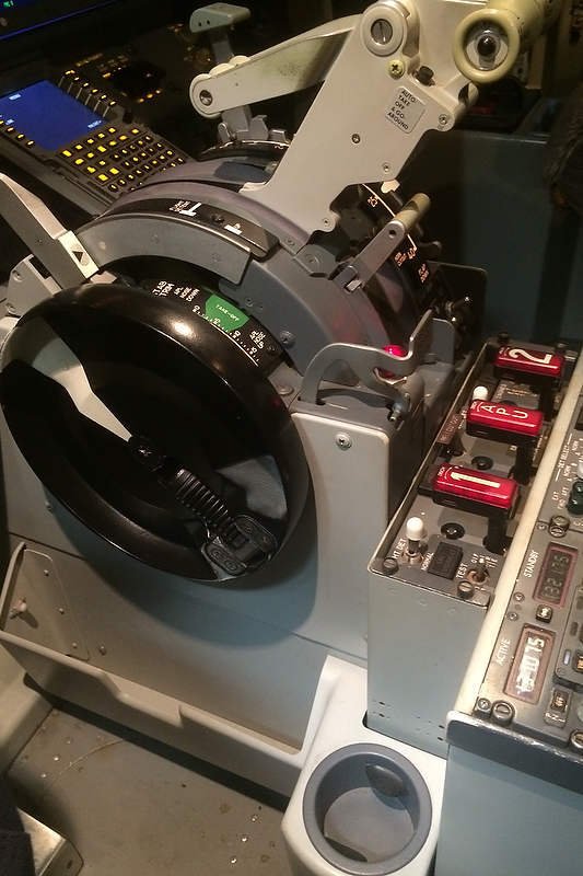
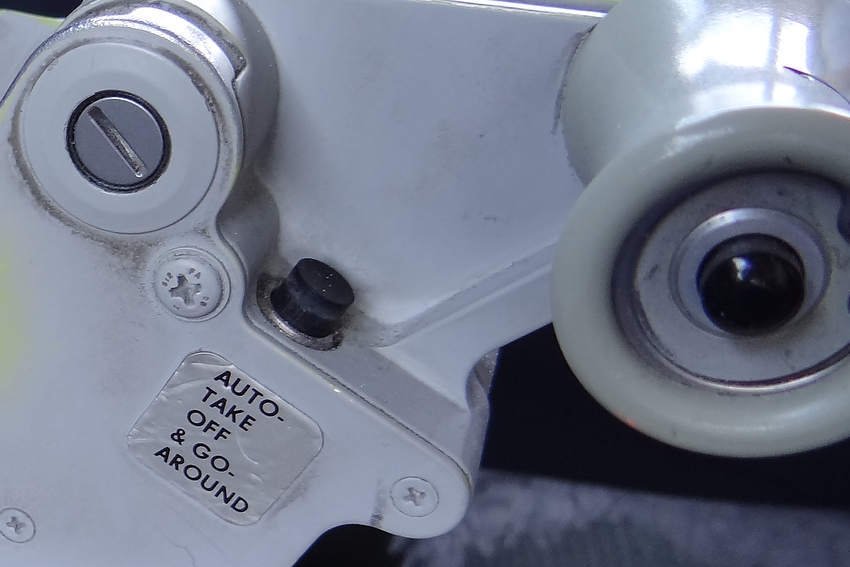
The actuator will be engaged (circuit closed) only if the micro-switch (located on the vertical rod mentioned earlier) connection is severed (parking brake lever is in the raised position closing the circuit).

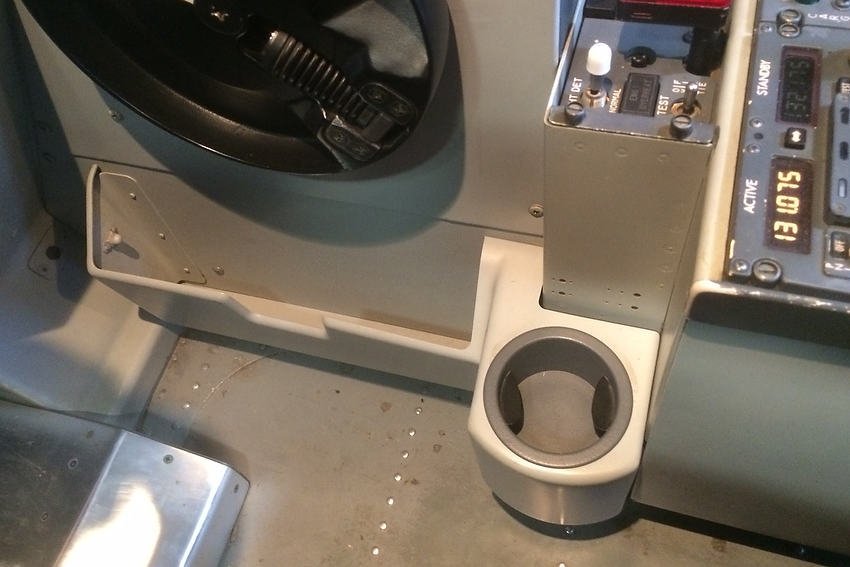
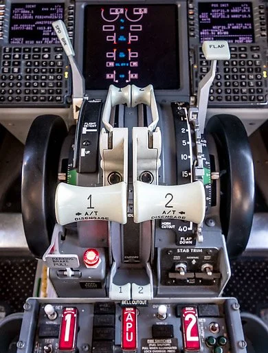
Actuator Power and Caution LED

The actuator, powered by 12 volts is connected to the 12 volt busbar in the Throttle Communication Module (TCM) and then, via a straight-through cable, to the Throttle Interface Module (TIM).  The relay for the parking brake mechanism is located in the TIM.

The design of an actuator is such, that if power is continuously applied to the mechanism, it will burn out.  If operating correctly, the actuator will onlt receive power when the toe brakes are depressed and the parking brake lever is raised at the same time.

To combat against the unforeseen event of power being continuously supplied to the actuator, for example by a relay that is stuck in the open (on) position, a coloured LED has been incorporated into the three LEDs that are fitted to the front of the Throttle Communication Module (TCM).  This flashing purple coloured LED illuminates only when the circuit is closed and the actuator is receiving 12 volt power.

Important Point:

  • Two terms often confused are open circuit and closed in relation to an electrical circuit.

Any circuit which is not complete is considered an open circuit.  Conversely, a circuit is considered to be a closed circuit when electricity flows from an energy source to the desired endpoint of the circuit.

Conversely, a closed relay means it allows voltage to travel through it, while an open relay is the opposite.

Additional Information

Like many things, there are several ways to accomplish the same or a similar task.  The following posts located in the ProSim737 forum discuss the conversion of the parking brake lever.

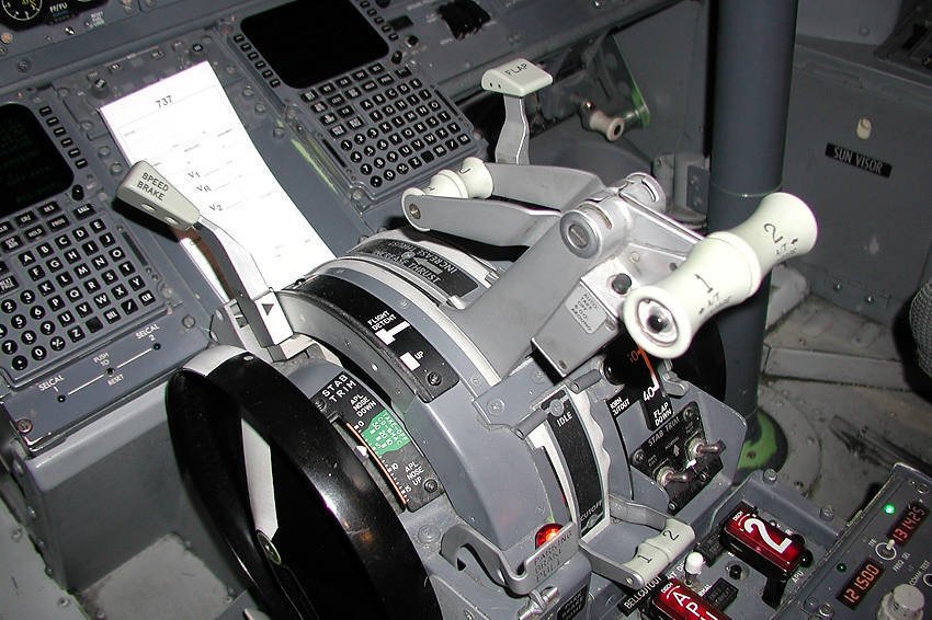
  • This article is one of several pertaining to the conversion of the OEM Throttle Quadrant

  • NOTE:  Since publication, ProSim-AR has incorporated into their software a parking brake release 'command'.  This by-passes the need to use the USER OUT settings mentioned above.  The command is set to the output on the Phidget 0/0/8 card.  The parking brake release can be found in the Configuration/Gates menu.  (MORE TO COME - in construction).

Throttle Quadrant Rebuild - Speedbrake Motor and Clutch Assembly Replacement

The motor that provides the power to move the speedbrake lever is attached via a slipper clutch to the speedbrake control rod. The slipper clutch can easily be adjusted and if set correctly provides the correct torque required for the speedbrake lever to move.   Below the motor is the Throttle Communication Module (TCM) that accommodates, amongst other things, the relays that are used by the logic to control the speedbrake lever's movemen

The mechanics of the speedbrake system has been completely overhauled, however, the logic that controls the speedbrake has remained ss it was. 

Several problems developed in the earlier conversion that could not be successfully rectified.  In particular, the speed of the speedbrake lever when deployed was either too fast, too slow, or did not move at all, and the clutch mechanism frequently became loose. 

Other minor issues related to the condition korrys that illuminate when the speedbrake is either armed or extended; these korrys did not always illuminate at the correct times.

The slipper clutch can easily be adjusted and if set correctly provides the correct torque required for the speedbrake lever to move.   Below the motor is the Throttle Communication Module (TCM) that accommodates, amongst other things, the relays that are used by the logic to control the speedbrake lever's movement.

Rather than continually‘tweak the earlier system, it was decided to replace the motor and clutch assembly with a more advanced and reliable system. To solve the arming issue, a linear throw potentiometer has been used to enable accurate calibration of the speedbrake lever in Prosim737.

Important Point:

  • To read about the first conversion and learn a little more about closed-loop systems and how the speedbrake works, please read the companion article PRIOR to reading this article.  This article only addresses the changes made to the system and builds on information discussed in the other article: 737 Throttle Quadrant  Speedbrake Conversion and Use

Motor and Clutch Assembly

A 12 volt motor is used to power the speed brake.  The motor is mounted forward of the throttle unit above the Throttle Communication Module (TCM).  The wiring from the motor is routed, in a lumen through the throttle firewall to a 12 volt busbar and relays.  The relays, mounted inside the TCM, are dedicated to the speedbrake. 

Attached to the 12 volt motor is a slipper-clutch assembly, similar in design to the slipper clutches used in the movement of the two throttle thrust levers.  The clutch can easily be loosed or tightened (using a pair of padded pliers) to provide the correct torque on the speedbrake lever, and once set will not become loose (unless exposed to constant vibration). 

diagram 1: slipper clutch cross section

The slipper clutch and bearings have been commercially made.

A linear throw potentiometer has been mounted on the Captain-sid of the quadrant.  The potentiometer enables the movement of the speedbrake lever to be finely calibrated in ProSim737

Speedbrake Mechanics

In the real Boeing 737 aircraft, buttons are located beneath the metal arc that the speedbrake travels.  If you listen carefully you can hear the buttons clicking as the lever moves over the button.  These on/off buttons activate as the speedbrake lever travels over them, triggering logic that causes the speedbrake to move.

This system has been replicated by using strategically placed micro-buttons beneath the speedbrake lever arc.  As the speedbrake lever moves over one of the buttons, the button will trigger a relay to either open or close (on/off).  The four relays, which are mounted in the Throttle Communication Module (TCM) trigger whether the speedbrake will be armed, stowed, engaged on landing, or placed in the UP position.

Speedbrake Korry (armed and extended)

The speedbrake system is a closed system, meaning it does not require any interaction with the avionics suite (ProSim737), however, the illumination of the condition lights (speedbrake armed and extended on the MIP) is not part of the closed loop system.  As such, the korrys must be configured in ProSim737 (switches/indicators). 

An easy workaround to include the arm korry to the closed loop system is to install a micro-switch under the speedbrake lever arc to correspond to the position of the lever when moved to the armed position.  Everytime the level over the micro-switch the arm korry will illuminate.

Speedbrake Operation

To connect the mechanical system to the avionics (ProSim737), a linear throw potentiometer has been connected to a Leo Bodnar BU0836A Joystick Controller card.  This enables the movement of the speedbrake lever to be calibrated in such a way that corresponds to the illumination of the korrys and the extension of the spoilers on the flight model.  The potentiometer has been mounted to the throttle superstructure on the Captain-side.

Using a potentiometer enables the DOWN and ARM positon to be precisely calibrated in ProSim737 (config/configuration/combined config/throttle/mcp/Levers).

The following conditions will cause the speedbrake lever to deploy from the DOWN to the UP position.

  1. When the aircraft lands and the squat switch is activated;

  2. During a Rejected Takeoff (RTO).  Assuming the autobrake selector switch has been set to RTO, there is active wheel spin, and the groundspeed exceeds 80 knots; and,

  3. If the reverse thrust is engaged with a positive wheel spin and a ground speed in excess of 100 knots.

Point (iii) is worth expanding upon.  The speedbrake system (in the real aircraft) has a built-in redundancy in that if the flight crew forget to arm the speedbrake system and make a landing, the system will automatically engage the spoilers when reverse thrust is engaged.  This redundant system was installed into the Next Generation airframe after several occurrences of pilots forgetting to arm the speedbrake prior to landing.  

Therefore, the speedbrake will deploy on landing either by activation of the squat switch (if the speedbrake was armed), or when reverse thrust is applied.

Speedbrake Logic ( programmed variables)

The following variables have been programmed into the logic that controls the operation of the speedbrake.

  1. Rejected Take Off (RTO).  This will occur after 80 knots call-out.  Spoilers will extend to the UP position  when reverse thrust is applied.  The speedbrake lever moves to UP position on throttle quadrant.  RTO must be armed prior to takeoff roll;

  2. Spoilers extend on landing when the squat switch is activated.  For this to occur, both throttle thrust levers must be at idle (at the stops).  The speedbrake lever also must be in the armed position prior to landing.  The speedbrake lever moves to UP position on throttle quadrant;

  3. Spoilers extend automatically and the speedbrake lever moves to the UP position when reverse thrust is applied;

  4. Spoilers close and the speedbrake lever moves to the DOWN position on throttle quadrant when the thrust levers are advanced after landing (auto-stow); and,

  5. Speedbrakes extend incrementally in the air dependent on lever position (flight detent).

The logic for the speedbrake is 'hardwired' into the Alpha Quadrant card.  The logic has not changed from what it was previously.

Speedbrake Lever Speed

When the speedbrake lever is engaged, the speed at which lever moves is quite fast.  The term ‘biscuit cutter’ best describes the energy that is generated when the lever is moving; it certainly will break a biscuit in two as well as a lead pencil.  Speaking of lead pencils, I have been told a favorite trick of pilots from yesteryear, was to rest a pencil on the throttle so that when the speedbrake engaged the pencil would be snapped in two by the lever!

The actuator that controls the movement of the speedbrake.  This image was taken from beneath the floor structure of a Boeing 600 aircraft.  Image copyright to Karl Penrose

In the real Boeing 737 aircraft the movement of the lever is marginally slower and is controlled by an electrically operated actuator (28 volts DC). 

In theory, the moderate speed that the speedbrake lever moves in the real aircraft should be able to be duplicated; for example, by suppressing the voltage from the 12 volt motor by the use of a capacitor, using a power supply lower than 12 volts, or by using speed controllers.  These alternatives have yet to be trailed.

It is unfortunate, that most throttle quadrants for sale do not include the actuator.  The actuator is not part of the throttle unit itself, but is located in the forward section under the flight deck.  The actuator is then connected to the speedbrake mechanism unit via a mechanical linkage.

In the real aircraft, the speedbrake lever and actuator provide the input via cables, that in-turn actuate the speedbrakes.  There is no feedback directly from the hydraulics and all operation is achieved via the manual or electric input of the speedbrake lever.

Actuator Sound

The sound of the actuator engaging can easily heard in the flight deck when the speedbrake engages (listen to the below video).  To replicate this sound, a recording of the actuator engaging was acquired.  The .wav sound file was then uploaded into the ProSim737 audio file library and configured to play when the speedbrake is commanded to move (squat switch).  

The .wav file can be shortened or lengthened to match the speed that the lever moves. 

Synopsis

I realize this and the companion article are probably confusing to understand.  In essence this is how the speedbrake operates:

  • A potentiometer enables accurate calibration (in ProSim737) of the DOWN and ARM position of the speedbreak lever.  This enables the condition korrys to illuminate at the correct time.

  • Micro-buttons have been installed below the arc that the speedbrake lever travels.  The position of each button, is in the same position as the on/off buttons used by Boeing  (the buttons are still present and you can hear them click as the speedbrake lever moves across a button).

  • The speedbrake system is a closed-loop system and does not require ProSim737 to operate.

  • The logic for the system has been programmed directly into the Alpha Quadrant card mounted in the Throttle Interface Module (TIM).  This logic triggers relays, located in the Throttle Communication Module (TCM) to turn either on or off as the speedbrake lever travels over the micro-buttons.  This is exactly how it's done in the real aircraft.

  • The micro-buttons are connected to a Phidget 0/0/8 relay card (4 relays).  The relay card is located within the Throttle Communication Module (TCM).

  • The speedbrake moves from the ARM position to the UP position when the squat switch is triggered (when the landing gear touches the runway).  The squat switch is a configured in ProSim737 (configuration/combined configuration/gate/squat switch).

Video

The upper video demonstrates the movement of the speedbrake lever.    The lower video, courtesy of U-Tube, shows the actual movement of the lever in a real Boeing aircraft.

The video is not intended for operational use, but has been shown to demonstrate the features of the speedbrake system.

If you listen carefully to both videos, you will note a difference in the noise that the actuator generates.  I have been informed that the 'whine' noise made by the actuator is slightly different depending upon the aircraft frame; the actuator in the older classic series Boeing being more of a high whine in comparison to the actuator in the Next Generation aircraft.


737-500 automated speedbrake deployment


Glossary

  • Condition(s) - A term referring to a specific parameter that is required to enable an action to occur.

  • FSUIPC - Flight Simulator Universal Inter-Process Communication.  A fancy term for software that interfaces between the flight simulator programme and other outside programmes.

  • Speedbrake Lever Arc - The curved arc that the speedbrake lever travels along.

  • Updated 11 July 2020.

B737 Original Equipment Manufacture RMI Knobs Fully Functional

oem rmi knobs mounted to the potentiometers that control the rmi

In two previous posts, I documented the installation of two bespoke reproduction RMI knobs and aN OEM ADF/VOR switch assembly mounted in the center pedestal.  The purpose of the switch assembly, which originally was used in a Boeing 727 airframe, was to provide an easy method to switch between ADF and VOR as the two knobs mounted on the RMI were non-functional.

With the acquisition of OEM RMI knobs, the next step was to implement the functionality of these knobs by installing micro-rotary switches to the RMI frame behind each knob.  The non Next Generation compliant RMI Switch Assembly panel would then be superfluous and removed from the center pedestal.

Installing the Micro-rotary Switches to the RMI Frame

The first step was to remove the RMI frame from the MIP and enlarge the holes that the RMI knobs reside.  This is to allow the installation of the two micro-rotary switches. To do this, a Dremel rotary tool was used.   

To enable the wires from the rotary switches to be routed neatly behind the RMI frame, a very narrow trench was cut into the rear of the plastic frame.  It is very important that this task is done with due diligence as the RMI frame produced by Flight Deck Solutions (FDS) is manufactured from ABS plastic and not metal – if the cut is too deep or too much pressure is applied to the Dremel, then the frame will be damaged.

The wires from the the RMI knobs are then laid inside the earlier cut trench and aluminum-based tape is  applied over the wires.  This ensures the wires are secure and do not dislodge from the RMI frame.

The micro-rotary switches used in this conversion are 1 cm in length (depth); therefore, to use these rotaries successfully you will need to have a certain amount of airspace between the rear of the RMI frame and front of the computer screen (central display unit).  Whether there is enough room to facilitate the installation of the rotary switch, will depend upon the manufacturer of the MIP and RMI frame – some manufacturers have allowed a centimeter or so of space behind the RMI frame while others have the frame more or less flush to the center display unit screen.  If the air space is minimal, the rear of the rotary may rub against the display unit.

RMI frame and OEM knobs connected to small rotary potentiometers.  Note the metal sleeve and grub screw in the knob.

There are several methods that can be used to secure the rotaries to the RMI frame.  By far the easiest is to enlarge the hole in the RMI frame to a diameter that the rotary can be firmly pushed through the hole and not work its way loose.  Another method, more permanent, is to glue the rotary inside the hole.  No matter which method used, the rotary must be secured inside the hole otherwise when the RMI knob is turned the rotary will swivel within the hole.

Once the rotaries are installed to the frame, the OEM knobs are carefully pushed over the rotaries and the metal grub screws on the knob tightened.  One of the benefits of using OEM knobs is that the inside of the knob has a metal sleeve which ensures that the knob will not wear out and slip with continual use – reproduction knobs rarely are manufactured with an inside metal sleeve.

Interface Card and Configuration

To enable functionality, the wires from the rotaries are carefully threaded through the MIP wall and routed to an interface card; A PoKeys card, mounted in the System Interface Module (SIM), has been used.  It is not necessary to use a large gauge wire to connect the rotaries to the interface card.  This is because the electrical impulse that travels through the wire is only when the RMI knob is turned, and then it is only for a scone or so.  

The functionality for the RMI knobs is configured within the ProSim737 avionics suite in the configuration/switches area of the software.

Micro-rotary Switches

There are several micro-rotary switches available in the market.  This conversion uses A6A sealed rotary DIP switches; they are compact and inexpensive.

When selecting a rotary, bear in mind that many rotaries are either two, three or four clicks in design.  This means that for a 90 degree turn, such as required when altering the RMI from VOR to ADF, the rotary will need to travel through a number of clicks to correspond with the visual position of the switch.

The A6A type mentioned above are a two click type.  The first click will change the designation (VOR to ADF or back again), however, for realism two clicks are made (90 degree turn).  At the time of the conversion it was not possible to find a small enough rotary that was one click.  Despite this shortcoming, the physical clicks are not very noticeable.

This conversion is very simple and is probably one of the easiest conversions that can be done to implement the use of OEM knobs.  There is minimal technical skill needed, but a steady hand and a good eye is needed to ensure the RMI frame is not damaged when preparing the frame for the installation of the two rotary switches.

oem rmi knobs in original plastic bag. note metal inner sleeve and grub screw

OEM RMI Gauge

This  conversion uses two OEM RMI knobs and rotaries to interface with the standard virtual RMI gauge provided within the ProSim737 avionics suite.  Converting an OEM RMI gauge for standalone operation is possible and has been accomplished by other enthusiasts; however, whether a full RMI conversion can be done very much depends upon your particular simulation set-up.

If a OEM RMI gauge is installed, there may be a spacing issue with the other alternate gauges.  In particular, the Integrated Standby Flight Display (ISFD) will require a smaller dedicated display screen.  Likewise, the EICAS display screen will need to be smaller so as to fit between the RMI gauge and the landing gear assembly.  Also, an extra display port will be required for the computer to read the ISFD display screen. 

Certainly, a complete conversion of a RMI gauge is the best way to proceed, if you already own a OEM RMI unit, and if the set-up problems are not too difficult to overcome.

Acronyms

  • MIP – Main Instrument Panel

  • OEM – Original Equipment Manufacturer

  • RMI – Radio Magnetic Indicator

Throttle Quadrant Rebuild - Clutch, Motors, and Potentiometers

Captain-side of throttle quadrant showing an overview of the new design.  The clutch assembly, motors, and  string potentiometer can be seen, in addition to a portion of the revised parking brake mechanism

An earlier article, Throttle Quadrant Rebuild – Evolution Has Led to Major Changes has outlined the main changes that have been made to the throttle quadrant during the rebuild process. 

This article will add detail and explain the decision making process behind the changes and the advantages they provide.  As such, a very brief overview of the earlier system will be made followed by an examination of the replacement system.

Limitation

It is not my intent to become bogged down in infinite detail; this would only serve to make the posts very long, complicated and difficult to understand, as the conversion of a throttle unit is not simplistic.

This said, the provided information should be enough to enable you to assimilate ideas that can be used in your project.  I hope you understand the reasoning for this decision.

The process of documenting the throttle quadrant rebuild will be recorded in a number of articles.  In his article I will discuss the clutch assembly, motors, and potentiometers. 

Why Rebuild The Throttle Quadrant

Put bluntly, the earlier conversion had several problems; there were shortfalls that needed improvement, and when work commenced to rectify these problems, it became apparent that it would be easier to begin again rather than retrofit. Moreover, the alterations spurred the design and development of two additional interface modules that control how the throttle quadrant was to be connected with the simulator.

TIM houses the interface cards responsible for the throttle operation while the TCM provides a communication gateway between TIM and the throttle.

Motor and Clutch Assembly - Poor Design (in previous conversion)

The previous throttle conversion used an inexpensive 12 volt motor to power the thrust lever handles forward and aft.  Prior to being used in the simulator, the motors were used to power electric automobile windows.  To move the thrust lever handles, an automobile fan belt was used to connect to a home-made clutch assembly.

This system was sourly lacking in that the fan belt continually slipped.  Likewise, the nut on the clutch assembly, designed to loosen or tighten the control on the fan belt, was either too tight or too loose - a happy medium was not possible.   Furthermore, the operation of the throttle caused the clutch nut to continually become loose requiring frequent adjustment.

The 12 volt motors, although suitable, were not designed to entertain the precision needed to synchronize the movement of the thrust levers; they were designed to push a window either up or down at a predefined speed on an automobile.

The torque produced from these motors was too great, and the physical backlash when the drive shaft moved was unacceptable.  The backlash transferred to the thrust levers causing the levers to jerk (jump) when the automation took control (google motor backlash).

This system was removed from the throttle.  Its replacement incorporated two commercial motors professionally attached to a clutch system using slipper clutches.

Close up image of the aluminium bar and ninety degree flange attachment.  The long-threaded screw connects with the tail of the respective thrust lever handle. An identical attachment at the end of the screw connects the screw to the large cog wheel that the thrust lever handles are attached

Clutch Assembly, Connection Bars and Slipper Clutches - New Design

Mounted to the floor of the throttle quadrant are two clutch assemblies (mounted beside each other) – one clutch assembly controls the Captain-side thrust lever handle while the other controls the First officer-side. 

Each assembly connects to the drive shaft of a respective motor and includes in its design a slipper clutch.  Each clutch assembly then connects to the respective thrust lever handle.  A wiring lumen connects the clutch assembly with each motor and a dedicated 12 volt power supply (mounted forward of the throttle quadrant).  See above image.

Connection Bars

diagram 1: crossection and a cut-away of a slipper clutch

To connect each clutch assembly to the respective thrust lever handle, two pieces of aluminium bar were engineered to fit over and attach to the shaft of each clutch assembly. 

Each metal bar connects to one of two long-threaded screws, which in turn connect directly with the tail of each thrust lever handle mounted to the main cog wheel in the throttle quadrant. 

Slipper Clutches

close up of slipper clutch showing precision ball bearings

A slipper clutch is a small mechanical device made from tempered steel, brass and aluminum.  The clutch consists of tensioned springs sandwiched between brass plates and interfaced with stainless-steel bearings.  The bearings enable ease of movement and ensure a long trouble-free life.

The adjustable springs are used to maintain constant pressure on the friction plates assuring constant torque is always applied to the clutch.  This controls any intermittent, continuous or overload slip.

A major advantage, other than their small size, is the ease at which the slipper clutches can be sandwiched into a clutch assembly.

Anatomy and Key Advantages of a Slipper Clutch

A number of manufacturers produce slipper clutches that are specific to a particular industry application, and while it's possible that a particular clutch will suit the purpose required, it's probably a better idea to have a slipper clutch engineered that is specific to your application. 

The benefit of having a clutch engineered is that you do not have to redesign the drive mechanism used with the clutch motors.

Key advantages in using slipper clutches are:

  • Variable torque;

  • Long life (on average 30 million cycles with torque applied);

  • Consistent, smooth and reliable operation with no lubrication required;

  • Bi-directional rotation; and,

  • Compact size.

The clutch assembly as seen from the First Officer side of the throttle quadrant.  Note the slipper clutch that is sandwiched between the assembly and the connection rods.  Each thrust lever handle has a dedicated motor, slipper clutch and connection rod.  The motor that powers the F/O side can be seen in the foreground

Clutch Motors

The two 12 Volt commercial-grade motors that provide the torque to drive the clutch assembly and movement of the thrust lever handles, have been specifically designed to be used with drives that incorporate slipper clutches.

In the real world, these motors are used in the railway and marine industry to drive high speed components.  As such, their design and build quality is excellent.

Each motor is manufactured from stainless steel parts and has a gearhead actuator that enables the motor to be operated in either forward or reverse.  Although the torque generated by the motor (18Nm stall torque) exceeds that required to move the thrust lever handles forward and aft, the high quality design of the motor removes all the backlash evident when using other commercial-grade motors.  The end result is an extraordinary smooth, and consistent operation when the thrust lever handles move.

A further benefit using this type of motor is its size.  Each motor can easily be mounted to the floor of the throttle quadrant; one motor on the Captain-side and the second motor on the First Officer-side.  This enables a more streamlined build without using the traditional approach of mounting the motors on the forward firewall of the throttle quadrant.

captain-side 12 Volt motor, wiring lumen and dual string potentiometer that control thrust levers

String Potentiometers - Thrust Levers 1/2

Two Bourne dual-string potentiometers have been mounted in the aft section of the throttle unit.  The two potentiometers are used to accurately calibrate the position of each thrust lever handle to a defined %N1 value.  The potentiometers are also used to calibrate differential reverse thrust.

The benefit of using Bourne potentiometers is that they are designed and constructed to military specification, are very durable, and are sealed.  The last point is important as sealed potentiometers will not, unlike a standard potentiometer, ingest dust and dirt.  This translates to zero maintenance.

Traditionally, string potentiometers have been mounted either forward or rear of the throttle quadrant; the downside being that considerable room is needed for the operational of the strings.  

In this build, the potentiometers were mounted on the floor of the throttle housing (adjacent to the motors) and the dual strings connected vertically, rather than horizontally.  This allowed maximum usage of the minimal space available inside the throttle unit.

Automation, Calibration and Movement

The automation of the throttle remains as it was.  However, the use of motors that generate no backlash, and the improved calibration gained from using string potentiometers, has enabled a synchronised movement of both thrust lever handles which is more consistent than previously experienced.

Reverse Thrust 1/2

Micro-buttons were used in the previous conversion to enable enable reverse thrust - reverse thrust was either on or off, and it was not possible to calibrate differential reverse thrust. 

Dual Bourne string potentiometer that enables accurate calibration of thrust lever handles and enables differential thrust when reversers are engaged

In the new design, the buttons have been replaced by two string potentiometers (mentioned earlier).  This enables each reverse thrust lever to be accurately calibrated to provide differential reverse thrust.  Additionally, because a string potentiometer has been used, the full range of movement that the reverse thrust is capable of can be used.

The video below demonstrates differential reverse thrust using theProSim737 avionics suite. The first segment displays equal reverse thrust while the second part of the video displays differential thrust.


Calibration

To correctly position the thrust lever handles in relation to %N1, calibration is done within the ProSim737 avionics software  In calibration/levers, the position of each thrust lever handle is accurately ‘registered’ by moving the tab and selecting minimum and maximum.  Unfortunately, this registration is rather arbitrary in that to obtain a correct setting, to ensure that both thrust lever handles are in the same position with identical %N1 outputs, the tab control must be tweaked left or right (followed by flight testing).

When tweaked correctly, the two thrust lever handles should, when the aircraft is hand-flown (manual flight), read an identical %N1 setting with both thrust levers positioned beside each other.  In automated flight the %N1 is controlled by the interface card settings (Polulu JRK cards or Alpha Quadrant cards).

Have The Changes Been Worthwhile

Comparing the new system with the old is 'chalk and cheese'.  

One of the main reasons for the improvement has been the benefits had from using high-end commercial-grade components.  In the previous conversion, I had used inexpensive potentiometers, unbalanced motors, and hobby-grade material.  Whilst this worked, the finesse needed was not there.

One of the main shortcomings in the previous conversion, was the backlash of the motors on the thrust lever handles.  When the handles were positioned in the aft position and automation was engaged, the handles would jump forward out of sync.  Furthermore, calibration with any degree of accuracy was very difficult, if not impossible. 

The replacement motors have completely removed this backlash, while the use of string potentiometers have enabled the position of each thrust lever handle to be finely calibrated, in so far, as each lever will creep slowly forward or aft in almost perfect harmony with the other.

An additional improvement not anticipated was with the installation of the two slipper clutches.  Previously, when hand-flying there was a binding feeling felt as the thrust lever handles were moved forward or aft.  Traditionally, this binding has been difficult to remove with older-style clutch systems, and in its worst case, has felt as if the thrust lever handles were attached to the ratchet of a bicycle chain.

The use of high-end slipper clutches has removed much of these feeling, and the result is a more or less smooth feeling as the thrust lever handles transition across the throttle arc.

Future Articles

Future articles will address the alterations made to the speedbrake, parking brake lever, and internal wiring, interfacing and calibration.  The rotation of the stab trim wheels and movement of the stab trim indicator tabs will be discussed.

This article is one of several that pertain to the conversion of the OEM throttle quadrant. A summary page with links can be viewed here: OEM Throttle Quadrant

Update

on 2018-04-11 01:08 by FLAPS 2 APPROACH

This article was not able to be published at an earlier time because of issues with confidentiality and potential patents.  The article has been re-written (March 2018). 

OEM Annunciators Replace Reproduction Korrys in Main Instrument Panel (MIP)

There can be little doubt that OEM annunciators shine far brighter than their reproduction counterparts.  The korrys are lit during the lights test. OEM Flaps gauge yet to be installed

A task completed recently has been the replacement of the reproduction annunciators located on the Main Instrument Panel (MIP) with OEM annunciators. 

The reason for changing to OEM annunciators was several-fold.  First, anything OEM is superior to a reproduction item.  Second, I wanted to reproduce the same korry annuciation  lighting observed in the OEM panels in the center pedestal, fire suppression panel, and when fitted, the forward and aft overhead panels.  Additionally, it was also to enable the push-to-test functionality and to provide better illuminance during daylight.  Some reproduction korrys are not that bright when annunciated and are difficult to see during the day.

This post will explain the anatomy of the annunciators that are fitted to the Main Instrument Panel (MIP).  It will also detail how the annunciators are wired and configured in ProSim737, and provide incite into some of the advantages and functionality that can be expected when using OEM annunciators.

The individual indexing can be observed on the top surface of the upper assembly (3 groves).  To separate the two assemblies a hex screw must be used to loosen the hex screw located inside the brass-coloured circular fitting.  Note that this is a new style LED korry which does not support the older incandescent bulbs

Anatomy of a Annunciator (Korry)

An annunciator is a light which is illuminated when a specific function occurs on the aircraft.  Annunciators are often called by the generic name ‘Korry’, as Korry is the registered trademark used by a company called Esterline that manufactures annunciators for the aero and space industry. 

There are two types of annunciators used in the Boeing aircraft, the 318 and the 319 which are either a Type 1 or Type 2 circuit. 

The 318 and 319 Korrys are not interchangeable.  Each Korry has a different style of bulb, differing electrical circuits, and a different method of internal attachment (captive hex screw verses two blade-style screws).  The only similarity between the 318 and 319 korrys is that the hole needed to house the korry in the MIP is identical in size - .440” x .940”.  The 318 Korry replaced the 319 Korry.

The circuit type refers to the electrical circuit used in the Korry.    Both circuit types require a ground-controlled circuit to turn it on, however, Type 1 circuits are ground-seeking while Type 2 circuits are power-seeking.    Visually (when installed to the MIP) the 318 and 319 korrys are indiscernible.

Annunciators have five parts that comprise:

(i)     The lower assembly and terminals (usually four terminals in number);

(ii)    The upper assembly;

(iii)    The outer housing/sleeve which has a lip to allow a firm connection with the MIP;

(iv)    The push-in light plate which includes the bulbs; and,

(v)    The legend, which incorporates a replaceable coloured lens.

The four terminal connections on the rear of each annunciator are specific to the functionality of the unit.  Each will exhibit a differing circuit dependent upon its function.  Likewise, each annunciator is individually indexed to ensure that the upper assembly cannot be inadvertently mated with the incorrect lower assembly.

Annunciators typically are powered by 28 Volts, use two incandescent ‘push-in style’ bulbs, and dependent upon the korry’s function, may have a light plate coloured amber, white red or green.  The legend is the name plate, and legends are usually laser engraved into the light plate to ensure ease of reading.  The engraved letters are in-filled with colour to allow the printing to stand out from the light plate’s lens colour.

Specialised Korry

The Boeing 737 aircraft uses a Korry, a type 318, that is slightly different to the standard Korry. This Korry enables the functionality for the BELOW G/S – P-Inhibit function.  

The Type 318 differs from other korrys used in the MIP in that it has a dry set of momentary contacts which are controlled by pressing the light plate.  Pressing the illuminated light plate extinguishes the annunciator and cancels the aural ‘Below Glideslope’ caution.

Reproduction Verses Original Equipment Manufacture (OEM)

The four biggest differences between reproduction and OEM annunciators are:

(i)     The ability to depress the light plate in the OEM unit for Push-To-Test function;

(ii)    The ability to replicate specific functions, for example the Below G/S P-Inhibit korry;

(iii)    The hue (colour) of the lens and crispness of the legend; and,

(iv)    The brightness of the annunciator when illuminated (5 volts verses 28 volts).

Reproduction Korry Shortfalls

Two areas lacking in reproduction units is the brightness of the annunciator when illuminated, and poorly defined legends.  

For the most part, reproductions use 5 volts to illuminate two LEDS located behind the lens.  Whilst it is true that the use of LED technology minimises power consumption and heat generation, the brightness of the LEDS, especially during the day,  may not be as bright as the two 28 volt incandescent bulbs used in an OEM annunciator.   Moreover, 5 volts does not allow the successful use of DIM functionality.  

It is unfortunate that many lower priced annunciators also lack well defined engraved lens plates making the ability to read the annunciator legend difficult at best.

Shortfalls notwithstanding, most high-end reproduction annunciators are of high quality and do the job very well.  


Table 1: quick reference to determine the main differences between OEM and reproduction annunciators. Note that the appearance of the annunciator can alter markedly between different manufacturers of reproduction units


Installation, Interfacing and Configuration of OEM Annunciators

Replacing a reproduction annunciator with its OEM counterpart is straightforward if the Main Instrument Panel (MIP) has been produced 1:1; however, reproduction MIPs are rarely exactly 1:1 and in all probability you may need to enlarge the hole that the annunciator resides.  If this is the case, ensure you use a fine-grade aluminum file and gentle abrade the hole to enlarge it.  When enlarging the hole, ensure you continually check the hole size by inserting the korry – if the hole is enlarged too much, the korry will be loose and will require additional methods to secure to the MIP.

korry system 318 type 1

Disassembling a Korry

It is important to understand how to unassemble the annunciator.  

First, the light plate has to be gently pried loose from the upper assembly.  Once this is done, the upper and lower assemblies must be separated to allow the outer/sleeve to be removed.  The Type 318 annunciators have a hex screw, located in the lower assembly unit, which needs to be loosened with a 5/64th hex wrench to allow separation, while the Type 319 annunciators are secured by two standard screws that require a small blade screwdriver.  

Once the two parts are separated, it should be noted that the upper assembly has a flange at the forward end; this flange enables the annunciator to be firmly connected to the MIP.   

Attaching a Korry to the MIP

Is your MIP 1:1 and will it fit OEM korrys without further to do?  Click the diagram to see the dimensions of korrys (with thanks to Mongoose for diagram)

Insert the upper assembly into the MIP flange facing forward.  Next, slide the housing over the rear of the mechanism from the rear of the MIP.  Rejoin the lower section and tighten the hex screw.    If the MIP is 1:1, the annunciator should now be firmly secured to the MIP wall. The light plate can now be pushed into the mechanism.

If the annunciator does not fit firmly into the MIP, it can be secured by using silastic or a glue/metal compound.  (I do not recommend this.  It is best to ensure the hole is the correct size or a tad too small.  This will guarantee that the annunciator will have a firm fit).

Provided the mechanism is not faulty or does not break, the chance that it will need to remove it is very remote.  If the bulbs fail, they are easily replaced as they are contained within the light plate.

Wiring - Procedure

Wiring the MIP annunciators is a convoluted and repetitious process that involves daisy-chaining the various annunciators together.  Because wiring is to and from four terminals, it can be difficult to remember which wire goes where.  As such, it is recommended to use coloured wire, label each wire and keep meticulous notes.  

Each annunciator has four terminals located on the rear of the unit that corresponds to:

(i)      Positive (28 volts);

(ii)     Logic for the function of the korry;

(iii)    Lights test; and,

(iv)    Push-To-Test.  

To crosscheck the above, each Type 2 korry has a circuit diagram stenciled on the side of the assembly.


Figure 1: A schematic of the three types of korrys used in the Boeing 737.  The left diagram is from the 318 push to inhibit korry (diagram copyright David C. Allen


For the OEM korrys to function correctly, they need to be connected with an interface card (I/O card).  An example of such a card is a Phidget 0/16/16 card.

(i)    Designate the annunciator closest the I/O card and power supply as the lead annunciator (alpha).  

(ii)    Terminal 1 and Terminal 4 are the power terminals for each korry.  Connect to the alpha korry the positive wire from the 28 Volt power supply to terminal 1 and the 28 Volt negative wire to terminal 4.  The wires from these two terminals are then daisy-chained to the identical terminals on the other korrys in the system.

(iii)    Terminal 2 controls the logic behind the function for each korry.  A wire must connect from terminal 2 of each korry to the output side of the I/O card.  To close the loop in the I/O card, a wire is placed from 28 Volts negative to the ground terminal on the card (input).

(iv)    Terminal 3 controls the logic behind the light test toggle.  A wire is daisy-chained from terminal 3 of the alpha korry to all other korrys in the system.  A wire is then extended from the final korry to the lights test toggle switch.  This switch has been discussed in detail in a separate post.

Quite a bit of wire will be needed to connect the thirteen or more annunciators and it is a good idea to try and keep the wire neat and tidy by using a lumen to secure it to the rear of the MIP.

Mounting and Brackets

Every simulator design is different, and what is suitable for one set-up may not be applicable to another.  

The I/O card that is used to control the MIP annunciators is mounted within the System Interface Module (SIM).  To this a straight-through cable is securely attached that connects to a D-Sub connector mounted on an aluminum bracket.  The bracket and two terminal blocks are strategically mounted on the rear of the MIP and enable the various wires from the korrys to connect with the straight-through cable.

Interfacing and Configuration Using ProSim737

To interface the annunciators, follow the directions on how to wire your I/O card.

This article provides information on the Phidget 21 Manager (software) and how a Phidget interface card is used.

If the annunciators have been correctly daisy-chained together, only the wires from terminal 2 of each korry will need to be connected to Phidget card.  When power is applied, the Phidgets software will automatically assign outputs to any device (korry) attached to the 0/16/16 card.  

To determine the digital output number for each annunciator, open the Phidgets 21 Manager, push the light plate on a chosen annunciator and record the allocated output number.  The output numbers are used by ProSim737 to allocate that annunciator to a specific software command line.  

Configuring the MIP annunciators in ProSim737 is a two-step process.  First, the annunciator must be assigned as a switch (for the puhs- to-test function to operate), then as an indicator (for the annunciator to illuminate).  Before commencing, check that Phidgets have been assigned in the driver section of the configuration section of the main ProSim737 menu.  

Open the configuration screen and select switches and scroll downwards until you find the appropriate switch that corresponds to the annunciator.  Assign this switch to the output number assigned by the Phidgets software (If you have multiple Phidget cards installed ensure the correct card is assigned).  

After this has been completed, continue the configuration process by assigning each annunciator to the appropriate indicator in the configuration/indicators section.

Lights Test

A lights test is used to determine whether all the annunciators are operating correctly.  A lights test can be accomplished two ways. 

The first method is to press the light plate of an annunciator which operates a momentary switch that causes the light to illuminate (push-to-test).  This is an ideal way to determine if an individual annunciator is working correctly.

The second method is to use the MIP toggle switch.  Engaging the toggle switch to the on position will illuminate all the annunciators that are connected to the toggle switch.  This is an excellent way to ensure all the annunciators are operational and is standard practice before beginning a flight.

It should be noted that for all the annunciators to illuminate, each korry must be connected to the toggle switch. 

An earlier post explained the conversion and use of a OEM Lights Test Toggle Switch.

The fire suppression panel annunciators are also korrys.  Like their MIP sisters, the korrys are very bright when illuminated as they are powered by 28 volts

Korry Systems

This post has discussed the main annunciators on the MIP which is but one system.  Other systems include the annunciators for the forward and aft overhead annunciators, fire suppression panel and several other panels.

To connect additional systems to the enable a full lights test to be done, an OEM aircraft high amperage relay can be used.  

OEM multi-relay device.  The relay from a Boeing aircraft is not necessary; any aircraft relay will suffice.  It's wise to choose a relay that has multiple connection posts as this will enable different systems to be connected to the relay.  The relay is easily fitted to the rear of the MIP or to the inside of the center pedesta

Depending upon the type of relay device used (there are several types), it may be possible to connect up to three systems to the one relay.  This is made possible by the OEM toggle switches unique multi-segment system, and the ability of the relay to handle high amperage from multiple aircraft systems.

A benefit of using an OEM relay is that it provides a central point for all wires from the various systems to attach, before connecting to the lights test toggle switch.  Note that 28 volts bmust be connected directly to the relay for correct operation.

The relay will, depending upon the throw of the toggle switch (lights test), open or close the circuit of the relay.  Opening rhe relay circuit (when the light test toggle is thrown) enables 28 volts to flow through the relay and illuminate any annunciators connected to the system.

Availability

The Korrys originally were used in British Airways 737-400 Airframe 25843

Fortunately, apart from a few functions, there is little difference between older style annunciators used in the classic series airframes and those used in the Next Generation aircraft - an annunciator is an annunciator no matter from what airframe (100 series, Classic or Next Generation).

Annunciators are relatively common and are often found ion e-Bay.  However, to acquire a complete collection that is NG compliant can be time consuming, unless a complete panel is purchased and the annunciators removed.

Lineage

The annunciators used in the simulator came from a B737-400 airframe.   This aircraft - serial number N843BB and construction number 25843 had a rather interesting lineage. 

It began service life in March 1992 with British Airways as G-DOCM before being transferred to Fly Dubai and Air One in 2004.  Late 2004 the airframe was purchased by Ryan International and the registration changed to N843BB.  Between 2005 and 2010 the aircraft was leased to the Sundowner LCC who at the time was contracted to the US Dept. of Justice.   The aircraft was returned to Ryan International mid 2010 and subsequently scrapped.

Acronyms